Butterfly Valve Assembly.
Creating Assembly of Butterfly Valve:
Now that we have created all the required parts of the Butterfly Valve, let's assemble them to make an actual model of the Butterfly Valve.
We will make a new file with the file type as the assembly in the Siemens NX and add all the components that we have designed till now with the help of the add component command.
All the following components such as Body, Shaft-Stem, Top Flange-Retainer, Disc-Plate, Lever-Handel, and Nut will be added to the assembly workbench.
Now that we have all the files required for making the assembly of the Butterfly Valve we can start constraining the parts according to the Butterfly Valve.
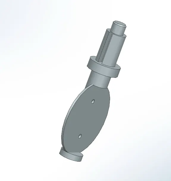
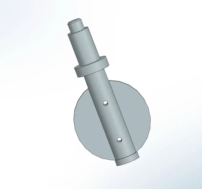
We will start constraining the Disc-Plate with the Shaft-Stem, for this we have to use the Assembly Constraints command:
1. We will try to constrain both the two holes of the Disc-Plate and the Shaft-Stem with an Orientation of Infer Center/Axis.
2. Now that we have constrained the holes let's used the orientation of Touch and attach both faces of the Disc-Plate and Shaft-Stem together.
The final output of the Disc-Plate and Shaft-Stem after the constraints will look as below:
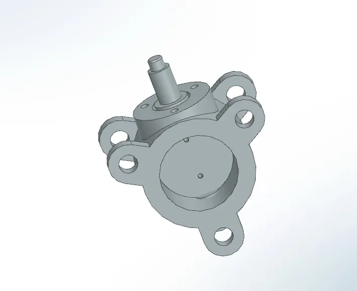
Now that we have completed the Disc-Plate and Shaft-Stem parts let's attach this to the body of the butterfly valve:
1. For this assembly part we will have to use the Orientation as Infer Center/Axis and select the axis of the shaft and the hole of the body.
2. Now that we have constrained the holes let's used the orientation of Touch and attach both faces of the Disc-Plate and the Body of the Valve.
The final output of the Disc-Shaft and Body after the constraints will look as below:
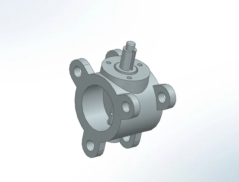
Now let's attach the Retainer to the rest of the assembly that we have created till now:
1. For this assembly part we will have to use the Orientation as Align and select the axis of all three holes of the retainer and align it with the holes of the body assembly.
2. Now that we have constrained the holes let's used the orientation of Touch and attach both faces of the retainer and the body together.
The final output of the Retainer and Body after the constraints will look as below:
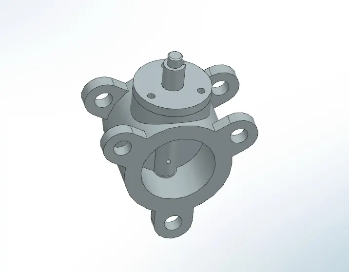
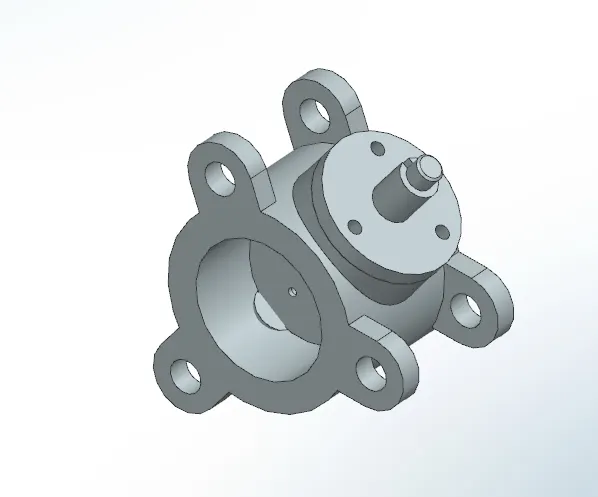
Its time to attach the Handle which opens and closes the Butterfly Valve:
1. For this assembly part, we will have to use the Orientation as Align and select the edge of the keyhole of the Handle and the edge of the keyhole of the Stem and align it together for the perfect fit of the key.
2. Now that we have constrained the keyhole alignment let's used the orientation of Touch and attach both faces of the Handle and the Retainer.
The final output of the Handle and the Retainer after the constraints will look as below:
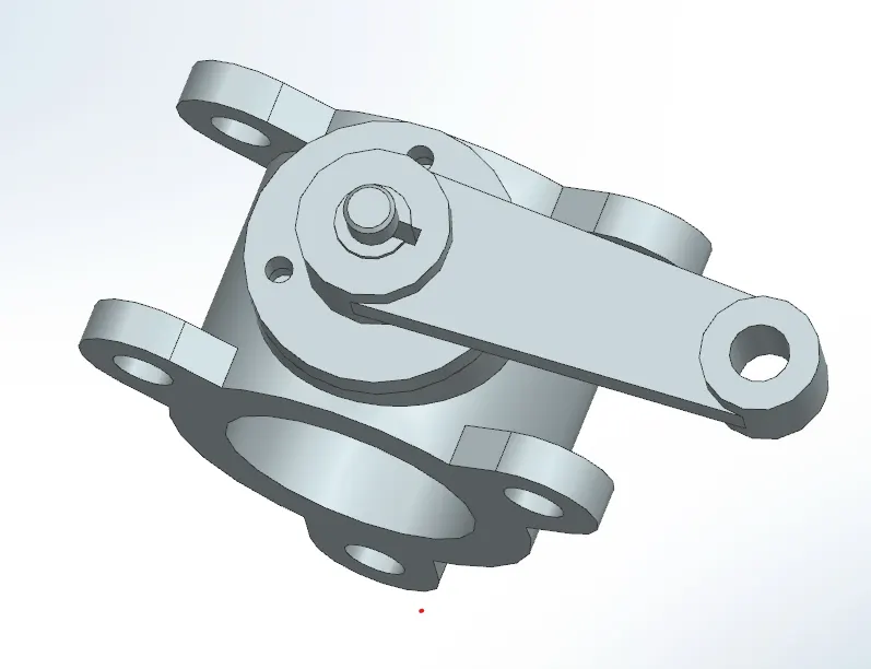
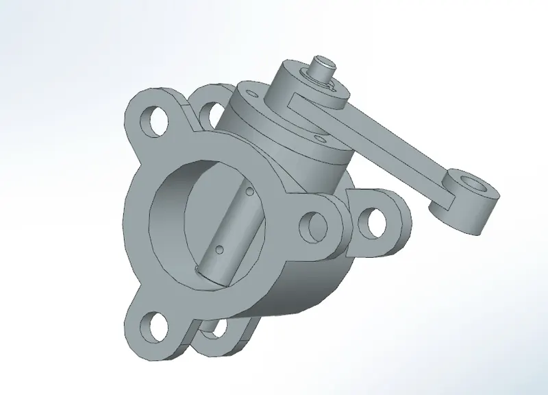
Lastly, now let's attach the Nut to the Assembly of the Butterfly Valve:
1. For this assembly part, we will have to use the Orientation as Infer Center/Axis and select the axis of the nut and the Axis of the Stem.
2. Now that we have constrained the axis of the Nut and the Stem let's use the orientation of Touch and attach both faces of the Nut and the Handle.
The final output of the Handle and the Retainer after the constraints will look as below:
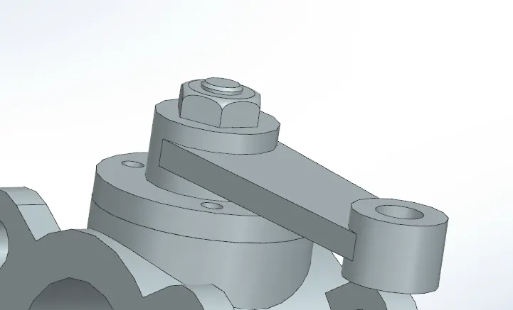
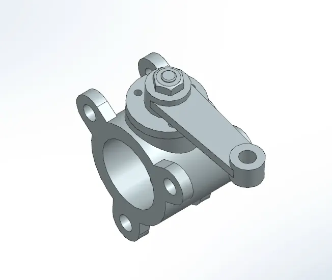
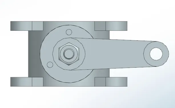
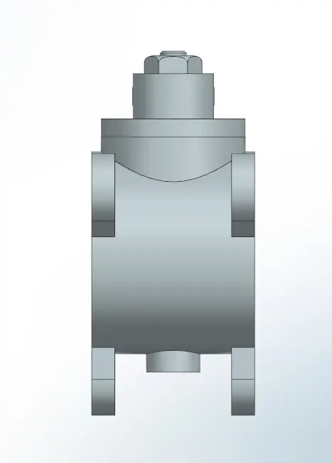
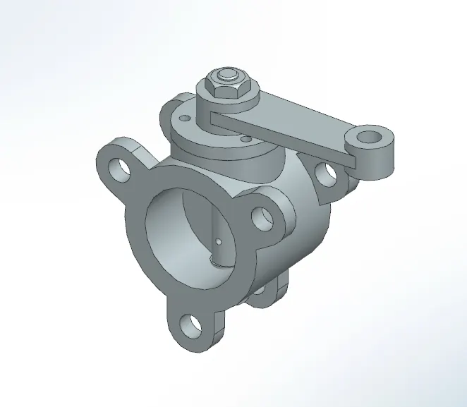
Now we have completed the whole assembly we have attached all the parts and created a final Butterfly Valve, bellow attached is the final look of the Butterfly Valve:
Front View of the Butterfly Valve:
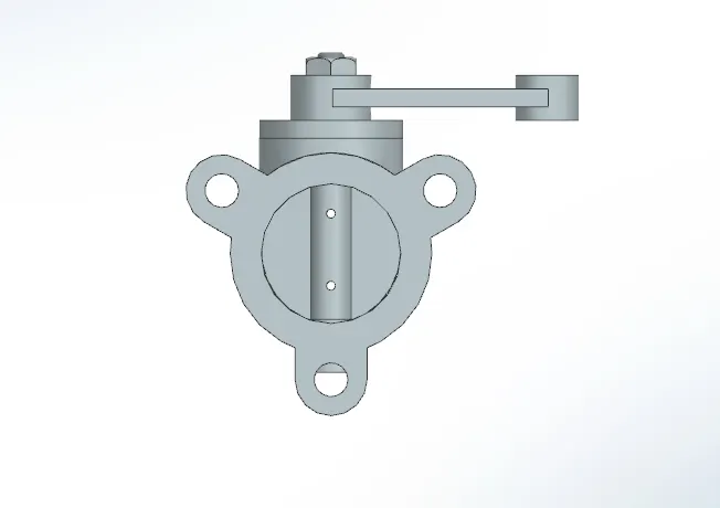
Top View of the Butterfly Valve:
Side View of the Butterfly Valve:
Isometric View of the Butterfly Valve:
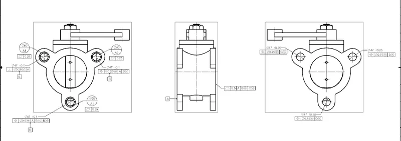
Now that we have completed the assembly of the Butterfly Valve we need to create the Drawing Sheet of the model with all the GD&T Fundamentals required:
Drawing sheet of the Butterfly Valve with all the GD&T Fundamentals:
Here we have included the Datum, Datum Targets, and Feature Control Frame.