Week 14 challenge
OBJECTIVE
Objectives of this project are:
- To design and assemble individual components of a butterfly valve to single working unit using NX-CAD
- To draft drawing sheet and apply GD&T to the butterfly valve assembly using NX-CAD.
INTRODUCTION
A butterfly valve is a mechanism that regulates the flow of fluid within large pipe diameters by the quarter-turn rotation of a disc. A rod or shaft feeds through the center of a disc and this shaft is connected to a lever handle that controls the motion of the disc. The disc position is either parallel or perpendicular to the flow of media. A butterfly valve differs from other valves because the disc is always in the flow direction causing a pressure change for any position of the valve. The butterfly valve gets its name from the movement mechanism, which is similar to a wing of flight. A butterfly valves motion is similar to that of a butterfly that has landed with the wings moved up and down with a 90-degree motion. The shaft is analogous to a butterfly’s body, while the disc moves like a butterfly wing.
A butterfly valve regulates the flow by starting, slowing, or stopping media. The disc opens and closes with a low-torque rotation of 90 degrees and works for any compatible application. Because they cost less and are lighter weight, the butterfly valve is often preferred over other types of valves. The butterfly valve is classified as a quarter-turn valve. It works like a ball valve for quick shutoff, but unlike a ball valve, the butterfly valve can also open and close incrementally. This difference means that the disc is always present in the flow and allows for a drop in pressure.
This disc is mounted at the center of the pipe. Disc movement is controlled by a shaft inserted through the disc and a lever handle, located outside the valve. Turning the lever handle positions, the disc either be perpendicular or parallel to the flow.
There are three main types of butterfly valve:
- Zero-offset butterfly valve
- High performance double-offset butterfly valve
- Triple offset butterfly valve
Parts of butterfly valve are:
- Butterfly valve main body
- Shaft
- Disc plate
- Retainer
- Lever handle
- Nut
GD&T INTRODUCTION
GD&T, short for Geometric Dimensioning and Tolerancing, is a system for defining and communicating design intent and engineering tolerances that helps engineers and manufacturers optimally control variations in manufacturing processes.There are several standards available worldwide that describe the symbols and define the rules used in GD&T. One such standard is the American Society of Mechanical Engineers -ASME Y14.5 (2018 latest).
The main benefits of using Geometric Dimensioning and Tolerancing (GD&T) are:
- Standardized design language
- Clear, precise and consistent communication between customers, suppliers, and production teams
- Method for calculating the worst-case mating limits
- Repeatable production and inspection processes
- Assembly is assured from qualified production parts
DESIGN & METHODOLOGY
1.Butterfly Valve Body
Butterfly valve body itself is one of the major components, that fits between two pipe flanges. The body is the housing for the internal components and it is the main part of the butterfly valve. The body connects to two pipes on its two sides and it regulates to flow.
To design and model the body in NX-CAD following commands were used:
- Sketch
- Extrude
- Pattern geometry
- Move feature
- Counterbored hole
- Boolean operations applied are: None, Unite, Substract
- Unite
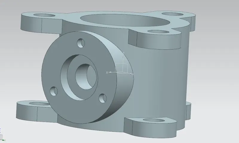
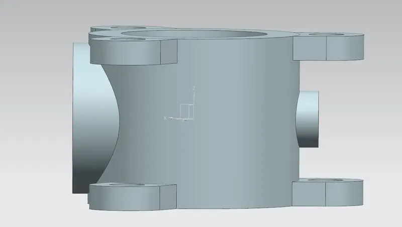
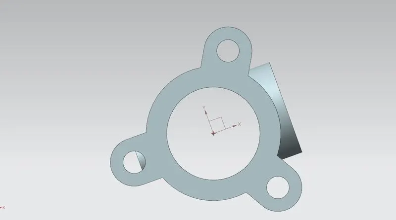
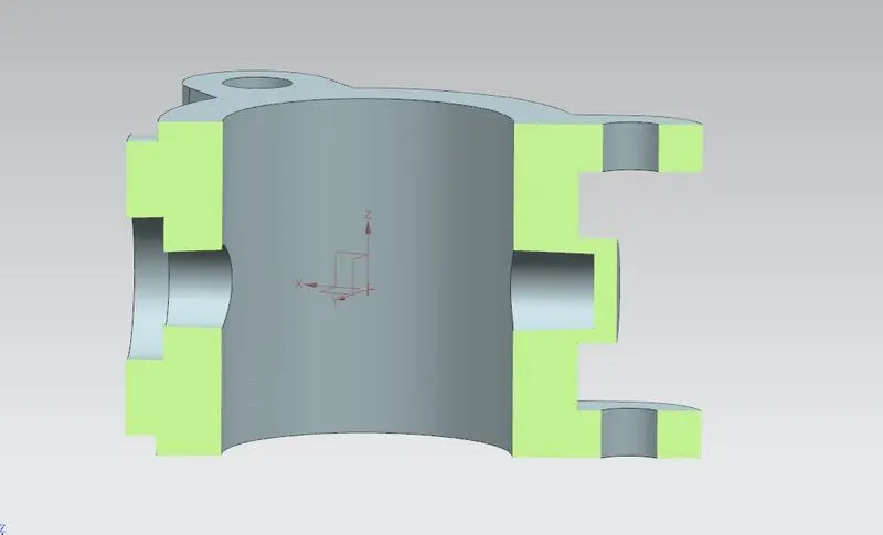
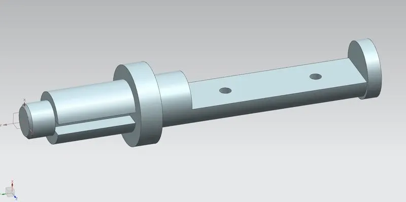
2.Shaft
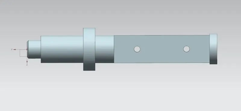
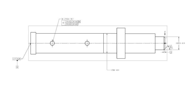
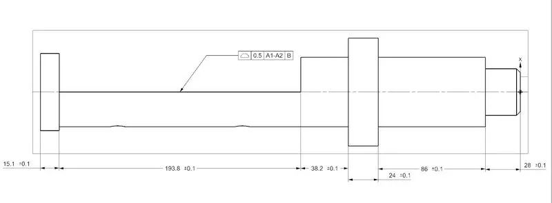
Shaft is an important component of the butterfly valve. It is assemblede inside to body of the valve and perpendicular to the direction of flow. It holds the disc plate which is also inside the body and is clamped with the lever outside the body.
The following commands were used in design and modelling the shaft body:
- Sketch
- Extrude
- Revolve
- Chamfer
- Boolean operation applied are: None, Subtract
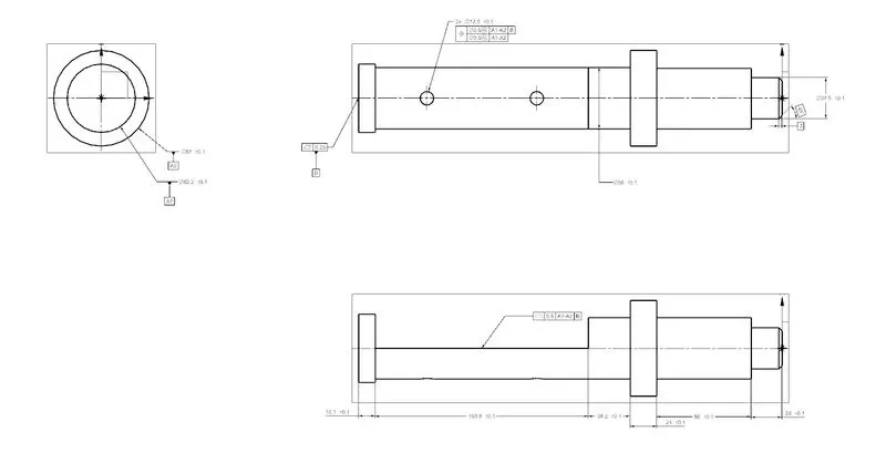
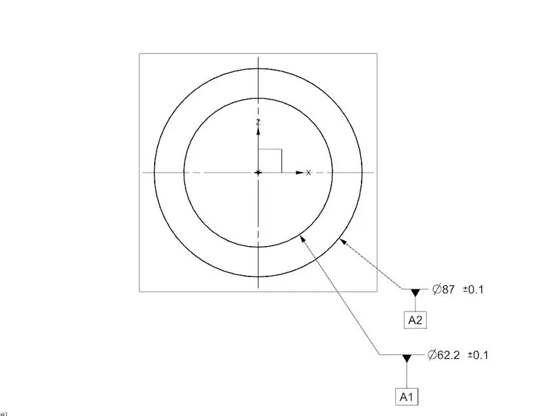
After the shaft body is modelled , the drawing sheet was drafted in the drafting application of NX-CAD and GD&T was applied to the drawing sheet.
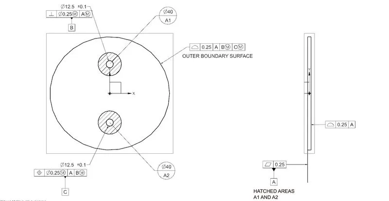
3.Disc Plate
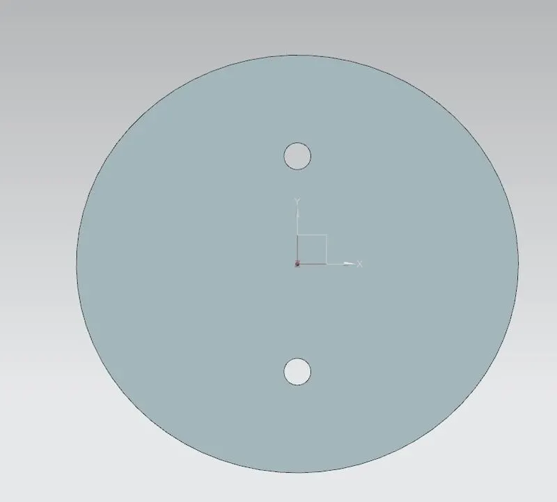
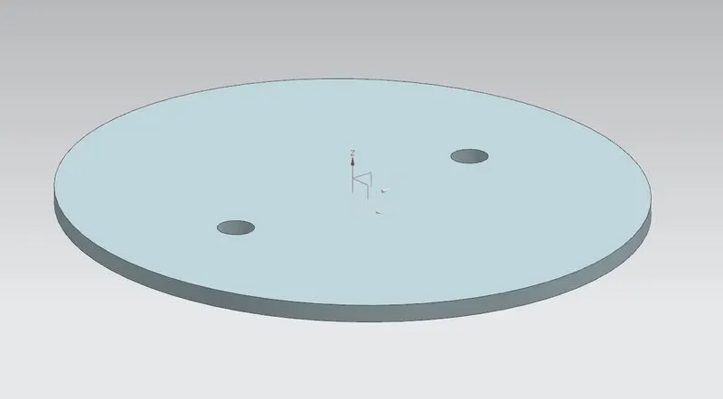
The disc plate is the other main component of the butterfly valve which regulates the flow in the valve. The orientation of this disc determines the flow rate of the fluid. The disc plate is of elliptical in profile. The holes in it help to position it properly to the shaft and is fastened using screws.
Commands used in modelling the disc plate in NX-CAD are:
- Sketch
- Extrude
GD&T was applied to the modelled part in drawing sheet.
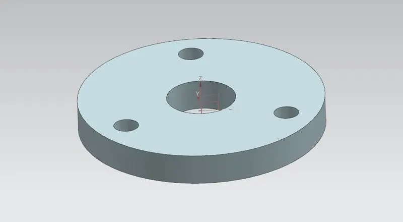
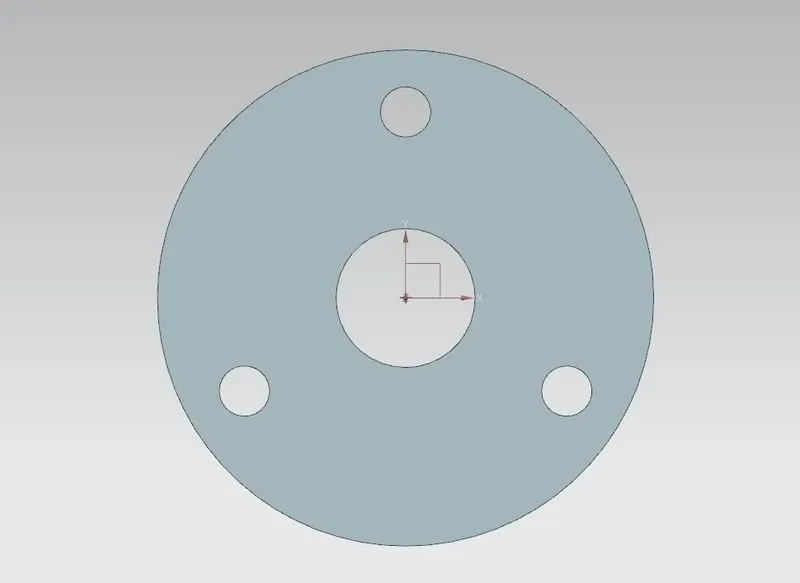
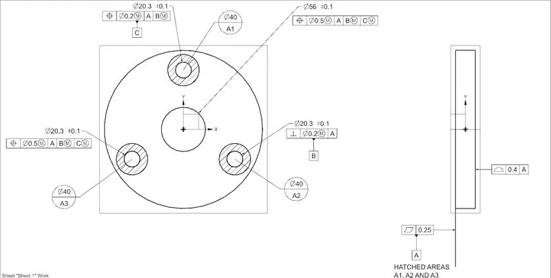
4.Retainer
The retainer helps to retain or to fix the shaft with the body of the butterfly valve. It keeps the shaft from coming out of the body and also keeps the disc inside the body operating properly.
Commands used in modelling retainer in NX-CAD are:
- Sketch
- Extrude
GD&T was also applied to the modelled part in drawing sheet using drafting application in NX-CAD.
5.Lever Handle
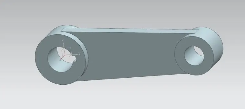
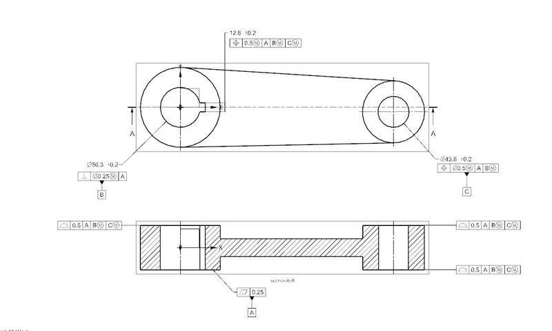
The lever handle is used to open and close the Butterfly Valve and also used to rotate the position of shaft, thus regulating the flow. It is fastened to the shaft with the aid of a key to secure it in place. The modelling of lever handle is done using NX-CAD with the following commands in operation:
- Sketch
- Arc
- Extrude
- Unite
The drawing sheet was also drafted using NX-CAD meeting all GD&T rules and dimensions for lever handle.
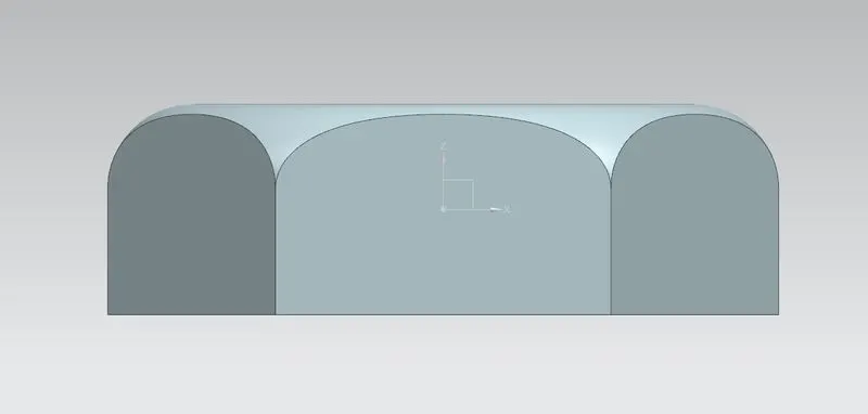
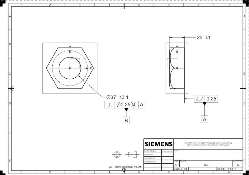
6.Nut
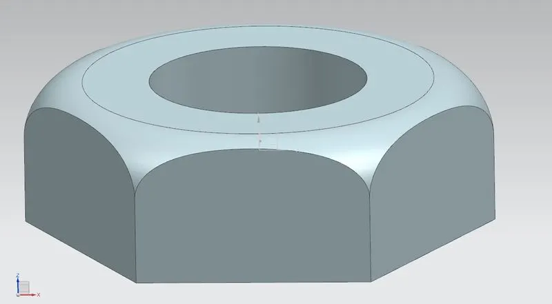
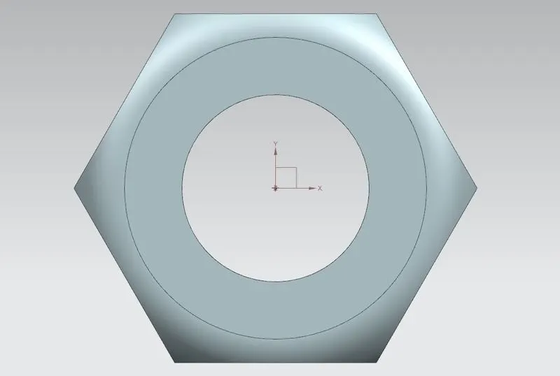
Nut helps to fix the lever in position with the shaft. It allows to keep it in position or to disassemble whenever required. The drawing sheet was also drafted using NX-CAD meeting all GD&T rules and dimensions for lever handle.
Commands used are:
- Sketch
- Extrude
- Revolve
7.Butterfly Valve Assembly
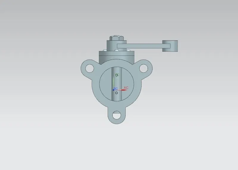
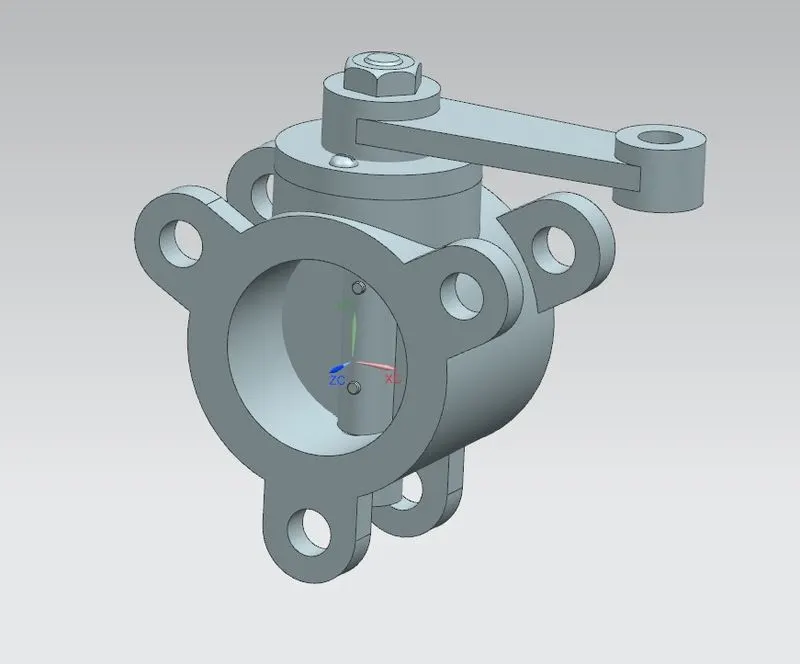
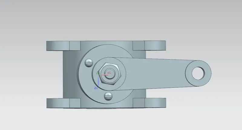
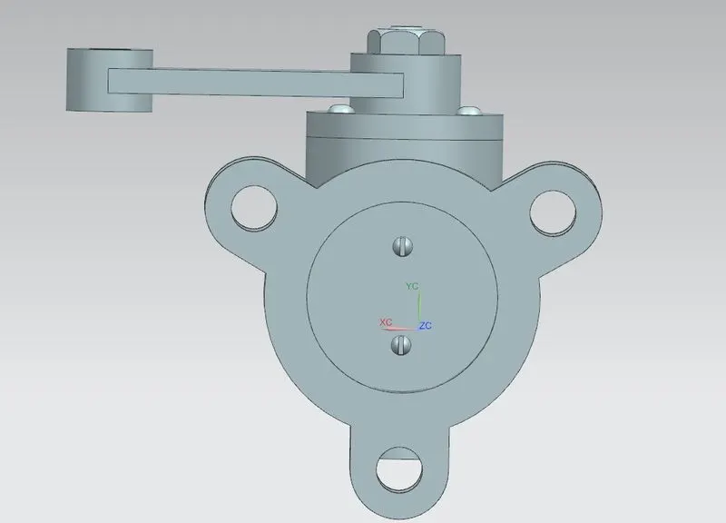
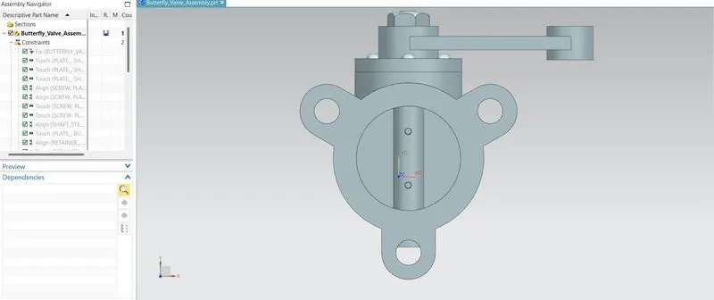
The assembly of butterfly valve is done by first fixing the main butterfly body by using fix contraint. Each components of butterfly valves are applied and assembled using assembly contraints.
Infer center/ axis contraints are applied to align the central axis of circular features. The assembly contraints commands used are:
- Infer center/ axis
- Touch
- Align
Drafting and GD&T
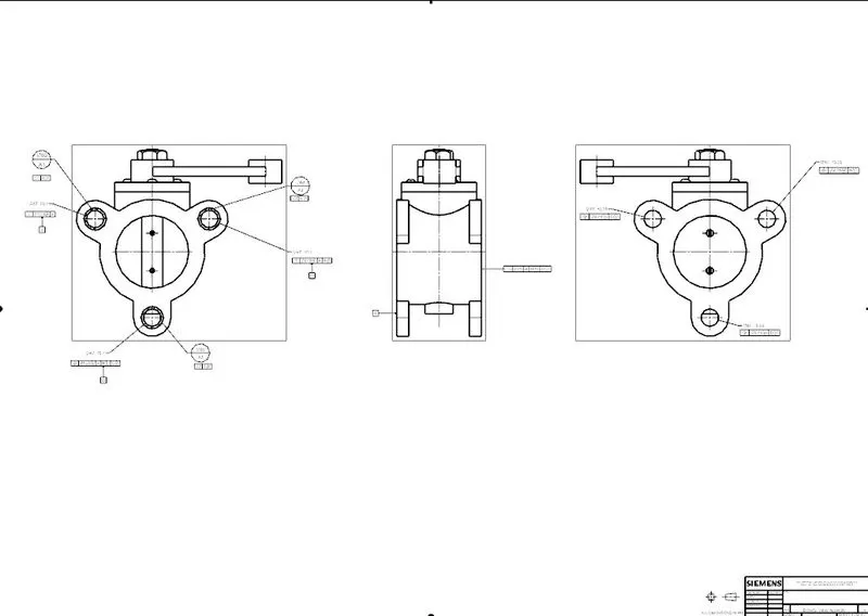
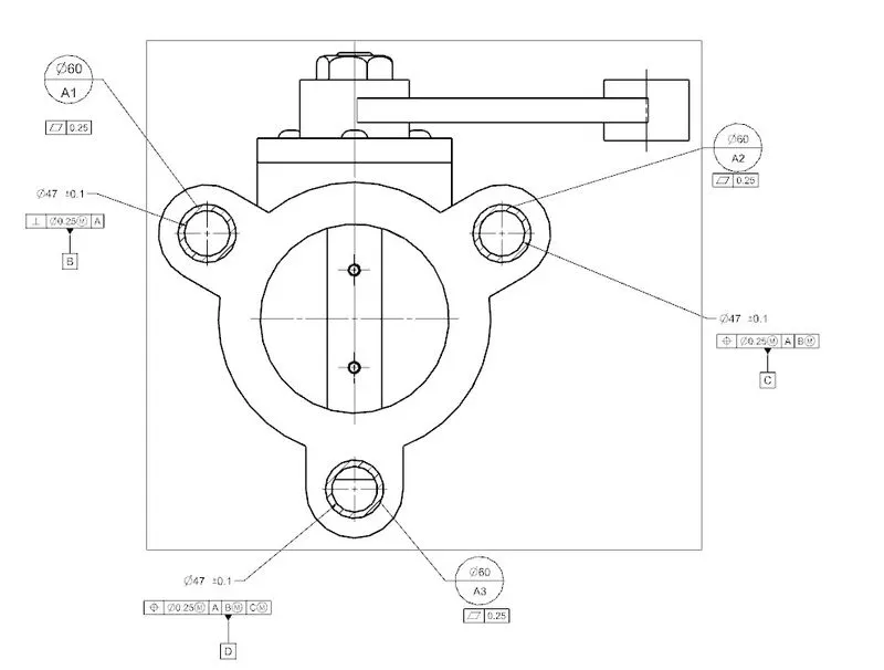
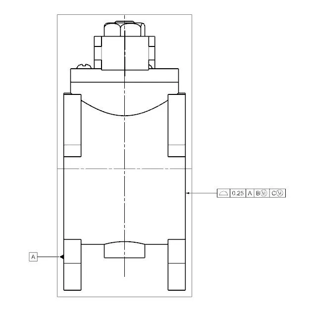
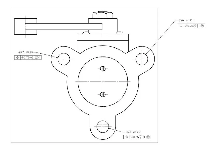
To apply the GD&T to this assembly, we need to apply it to the features which comes in contact with the other part and contribute to the positioning of the valve. Butterfly valve has only the 3 holes on each side of the body that comes in contact with two pipes. Primary datum A, is defined as the surface of 3 holes with the application of circular datum targets A1, A2 and A3. Perpendicular tolerance and position tolerances are applied to the respective holes in order to define secondary and tertiary datum and also a sub-datum D. Sub-Datum D is defined as the holes on the other sides should be aligned with the holes on one side, position tolerance is applied to each hole with respect to the datum of the opposite holes. Flatness tolerance is applied to the primary datum and profile tolerance is applied to the other side of the body.
CONCLUSION
Butterfly valve assembly was successfully modelled in NX-CAD and GD&T applied to all individual parts and the assembly of the Butterfly valve.