Week 14 challenge
Assemble and apply GD&T to the butterfly valve assembly drawing
Assembly
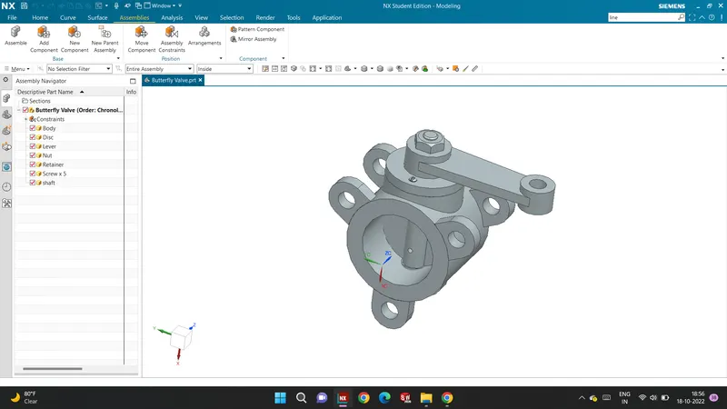
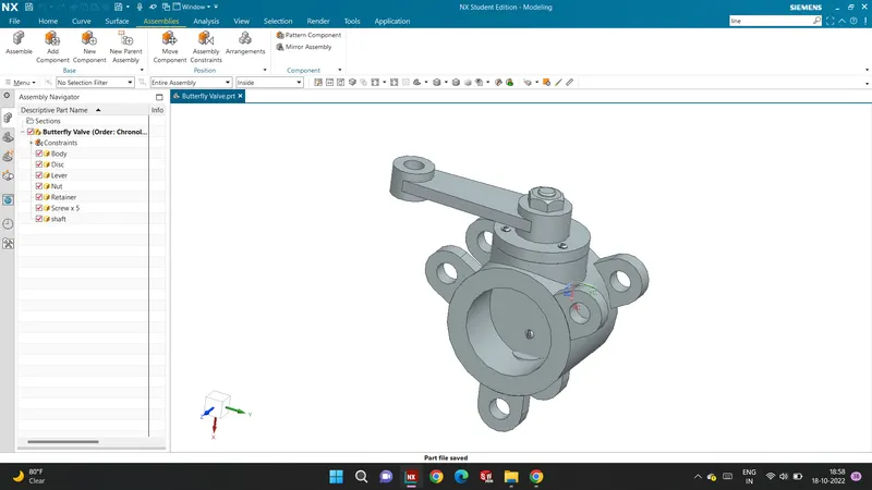
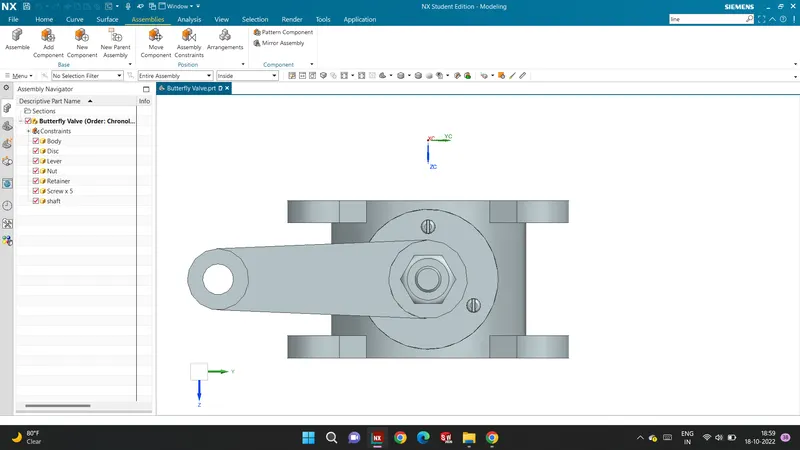
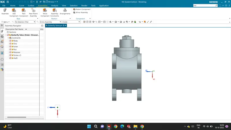
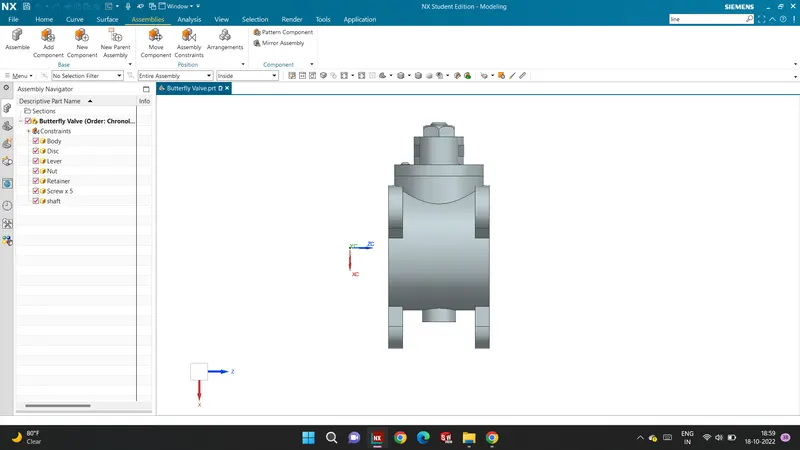
After the design, all the models should assemble with appropriate constraints. The assembly is created by first placing the body in position and mating other parts to it with the application of different joints provided in NX. First, the shaft and disc are joined together with the screws in place to create a sub-assembly which is then joined to the body in position. The retainer plate is then mated with the body and screws are used to fix them. After that, the lever is mated to the shaft in a position that is then fixed after the nut is mated with the shaft.
Features used to Assembly
- Infer Axis/center
- Touch Align
- Concentric
- Move Component
Methodology
The Assembly file is opened in NX CAD.
The above parts are added to the assembly file.
Now, one by one part is assembled using the Move part command and assembly constraint command.
Different constraints are used to assemble the butterfly valves, such constraints are Infer Axis, Touch, and Align.
Finally, the assembly of the butterfly valve is saved in the folder where all the other parts are saved.
Drafting Methodology
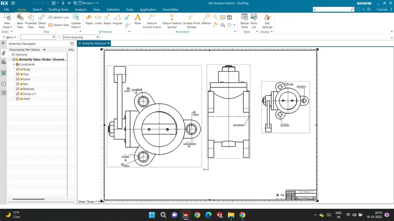
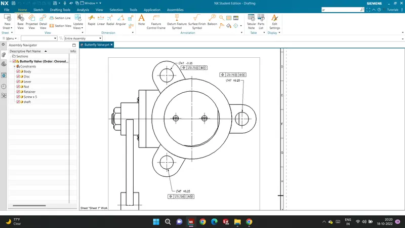
- Datum target areas A1, A2, and A3 are given to the ears of the butterfly valve.
- Datum target areas A2 and A3 are given with perpendicular tolerance and Position tolerance respectively.
- Sub datum D is given to the third ear.
- Finally, other tolerances are given to the surfaces and features of the Butterfly Valve.
Conclusion
In this project, a butterfly valve is designed and assembled in parametric CAD software, Siemens NX. GD&T according to ASME Y14.5 is applied at every stage of the part design process in order to make communication with the manufacturers effective and efficient. Hence, a design process in a real industrial manner is followed in this design of the butterfly valve understanding the design process more with the application of GD&T with industrial standards.