Week 14 challenge
Assemble and apply GD&T to the butterfly valve assembly drawing
Aim:
To create the Butterfly Valve part and assemble the part and also apply the GD&T with Drawing sheet
Objectives:
- The Main objective is to create and assemble the various component of butterfly valve using simens NX CAD
- Assemble all the individual parts of the butterfly
- Understand various GD&T symbols and how they apply to butterfly valve assemblies.
Introduction:
- Simens NX CAD:
NX, formerly known as "unigraphics", is a leading high-end CAD/CAM/CAE company owned by Siemens Digital Industries Software since 2007. In 2000, Unigraphics SDRC acquired his I-DEAS and he began to integrate aspects of both software packages into one product, which became Unigraphics NX or NX.
It is used in particular for:
- Design (parametric and direct solid/surface modeling)
- Engineering analysis (static, dynamic, electromagnetic, thermal using finite element method, and fluid flow using finite volume method).
- Create a finished design using the included editing module.
- Butterfly Valve:
A butterfly valve is a type of quarter-turn, rotary-acting valve used to block flow in pipelines. It is often said that butterfly valves can be used to regulate flow. However, it is not recommended to do this as it can damage the valve disc and impair its sealing properties.
- GD&T:
Geometric Dimensioning and Tolerancing (GD&T) is a system for defining and communicating engineering tolerances and relationships. It uses a symbolic language for engineering drawings and computer-generated 3D solid models that explicitly describe the nominal geometry and its permissible variations. This tells manufacturing personnel and machines what level of accuracy and precision is required for each controlled function of the part. GD&T is used to define the nominal (theoretically perfect) shape of a part or assembly, define the allowable variation in shape and possible size of individual features, and define the allowable variation between features .
Component Of Butterfly Valve:
- Body
- Shaft
- Disc Plate
- Lever
- Retainer
- Nut
- Butterfly Valve body:
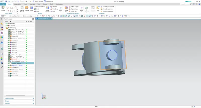
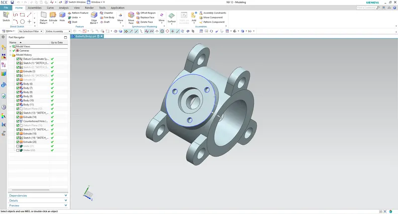
- The body is the housing of the internal components and the main part of the butterfly valve. The body is connected to two pipes on each side to regulate the flow. This part is created using simple functions such as rotating, extruding and moving objects in the NX modeling application.
- Initially, Select the XY coordinate and click on the line tool from the Sketch tab.
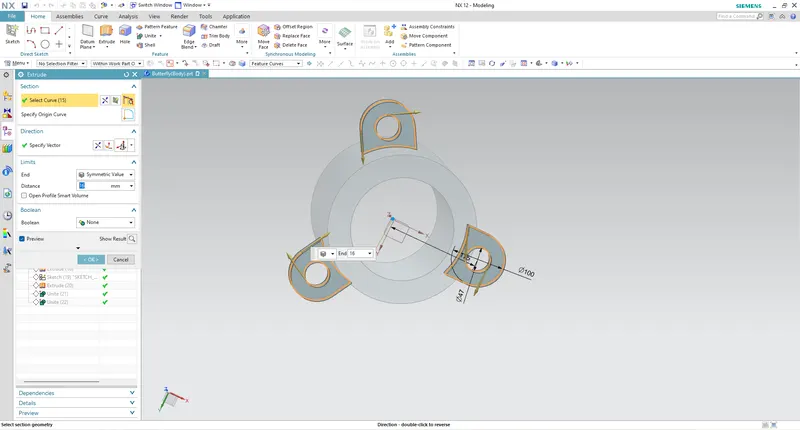
- I created a lugs on the midplane and extruded the lugs relative to the midplane (i.e. symmetrical values).
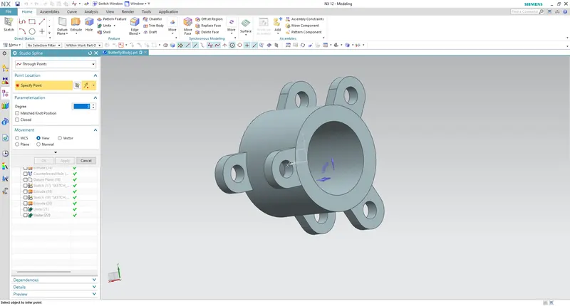
- I used the Move Object command to create similar tabs on the outer surface of the body using the tabs created earlier.
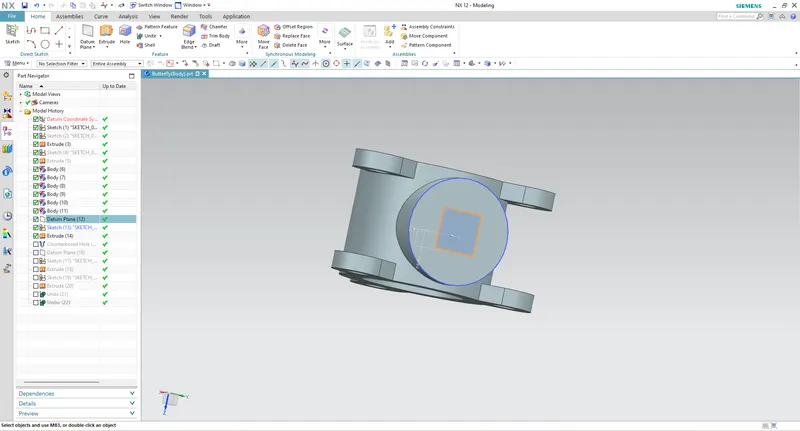
- Create a new datum plane and draw a circular sketch of the required diameter. Use the Extrude command to extrude this sketch into a cylindrical body.
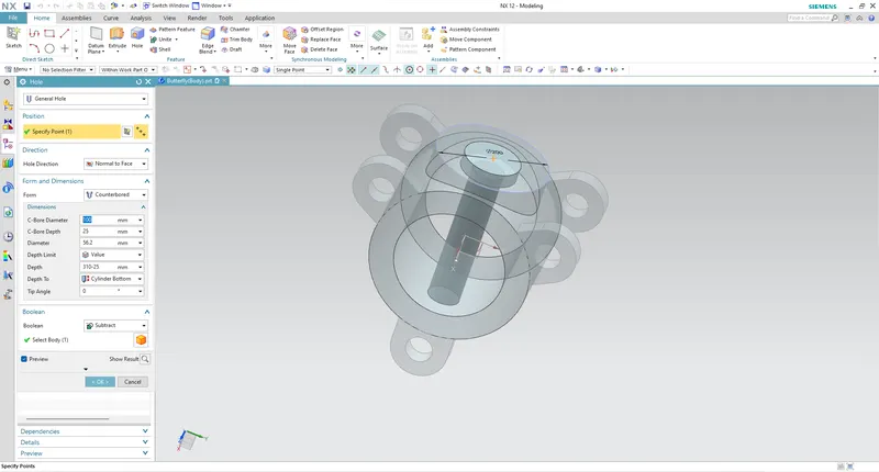
- Then use the Hole command to create a countersink in the body so that you can insert the shaft/stem. Enter all the required diameter and hole depth values accordingly.
- Create another datum plane on the opposite side of this newly created element. Create a circular sketch on this new layer and extrude it to the cylindrical body.
- Use the extrude command to create three small holes in the outer face of the sinkhole parent so that you can attach other components to the body.
- Shaft/Stem:
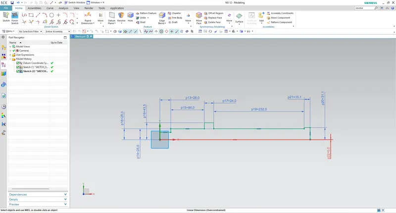
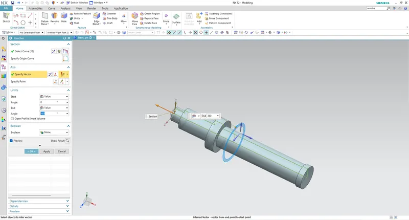
- Butterfly valve stems can be either one-piece or two-piece (split stems). This design features an integrated shaft. A washer/plate, lever and nut are attached to this shaft.
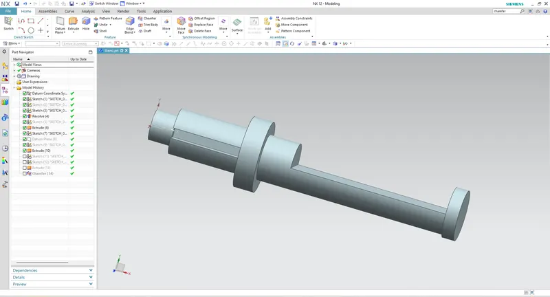
- First, create a sketch with a cylindrical shape and steps. This sketch must be fully constrained and closed to use the Revolve command.
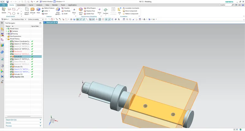
- After creating the body, we need to create two rectangular slots on it. one on XZ direction and another one in XY direction
- Once sketch finish should extrude the model
-
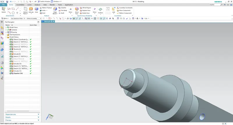
Then make two holes in front of the large slot where the disc/plate will be installed. Chamfered front circular edge for improved maneuverability and safety.
- Application of GD&T:
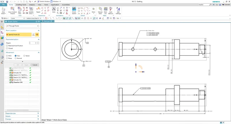
- The drawing of the shaft is created using an A1 size sheet.
- Since the shaft requires one degree of freedom to work efficiently, he uses only two reference points here.
- A1 and A2 dimensions are the dimensions of the part that contacts the butterfly valve body.
- Reference point B is the foot of the shaft.
- Different tolerances apply to some features that are critical to the function of the shaft.
- Disc Plate:
- The disc is simply the flow control/closure element of the butterfly valve mounted on the stem/shaft. The disk corresponds to the plug of plug valves, the gate of gate valves, and the ball of ball valves.
- A quarter turn or 90 degree rotation of the disc opens and closes the butterfly valve.
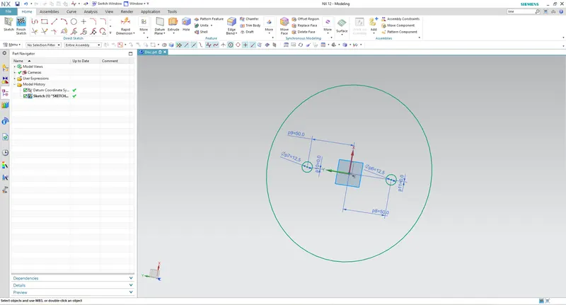
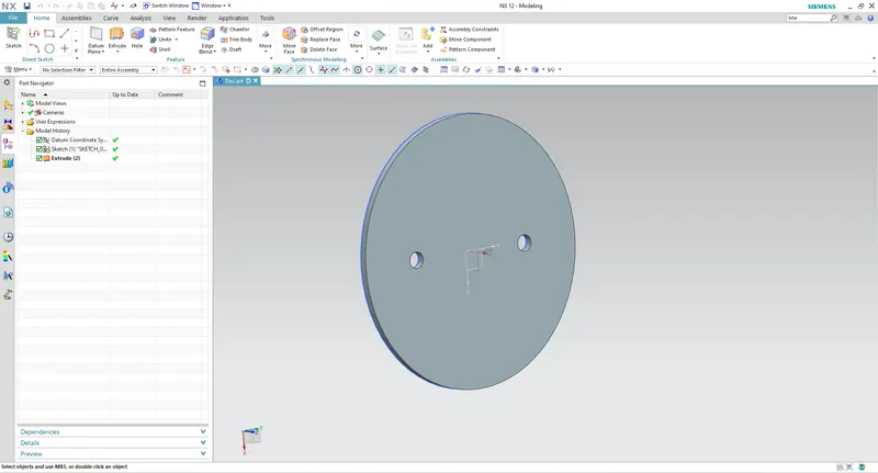
- Create an elliptical sketch of the appropriate size (long and short range). Next, drill two holes along the minor axis for attaching the disc to the shaft.
- Extrude the fully constrained sketch with the 6mm thickness.
- Application of GD&T:
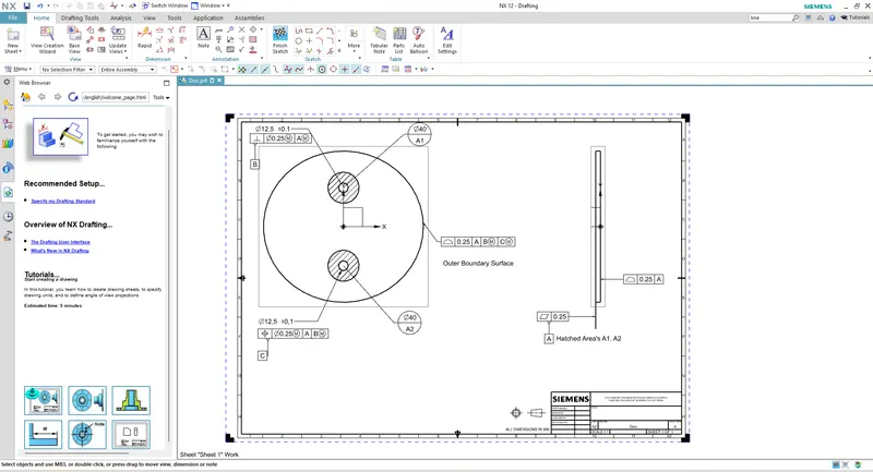
- After modeling, the part is passed to the design part, where three reference points A, B, and C are applied.
- The reference target areas A1, A2, A3 (primary reference value A) are arranged on the side of the retainer that contacts the upper body.
- Datum B is attached to one of the holes in the holder through which the bolt is inserted.
- Datum C is applied to the other hole in the retainer.
- Finally, other tolerances such as squareness, position and profile of one surface are applied to the other hole and holder surfaces. The drawing will be saved in the required folder.
- Retainer:
- It is just a type of washer that is attached to the body of the butterfly valve.
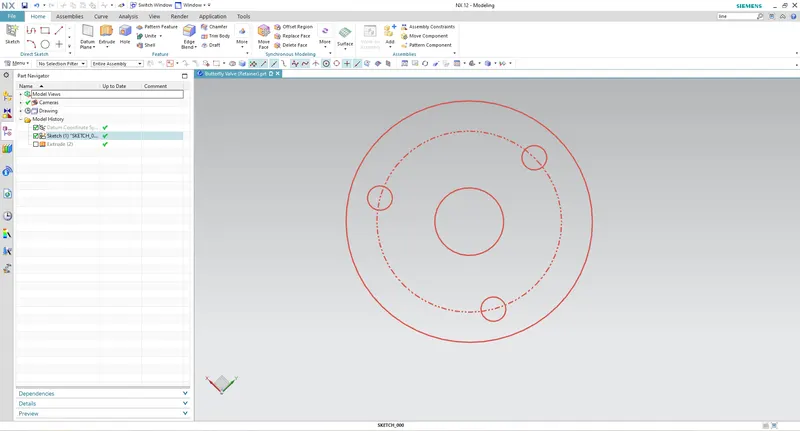
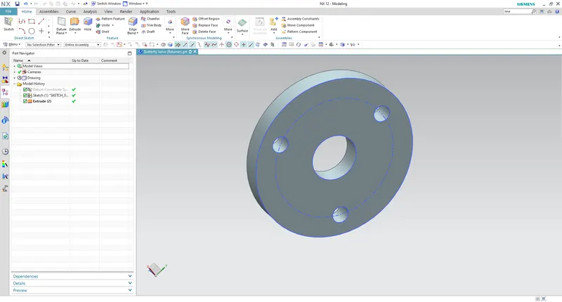
- Create a circular sketch of the appropriate diameter. Also in the sketch again creates three holes This will help attach the holder to the butterfly valve body.
- Once sketch finish should extrude the model
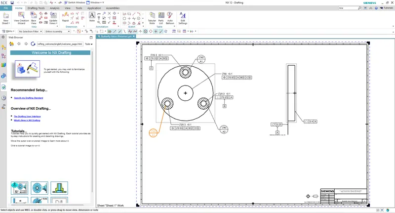
- Application of GD&T:
- After modeling, the part is passed to the design section, where three datum points A, B, and C are applied.Reference area A1, A2, A3
- The primary reference point A is located on the side of the retainer that contacts the top of the body.
- Datum B is attached to one of the holes in the holder through which the bolt is inserted.
- Datum C is applied to the other hole in the retainer.
- Finally, other tolerances such as squareness, position and profile of one surface are applied to the other hole and holder surfaces. The drawing will be saved in the required folder.
- Lever:
- This type Lever handle used for small butterfly valves. This allows you to adjust the flow by opening and closing the discs as needed.
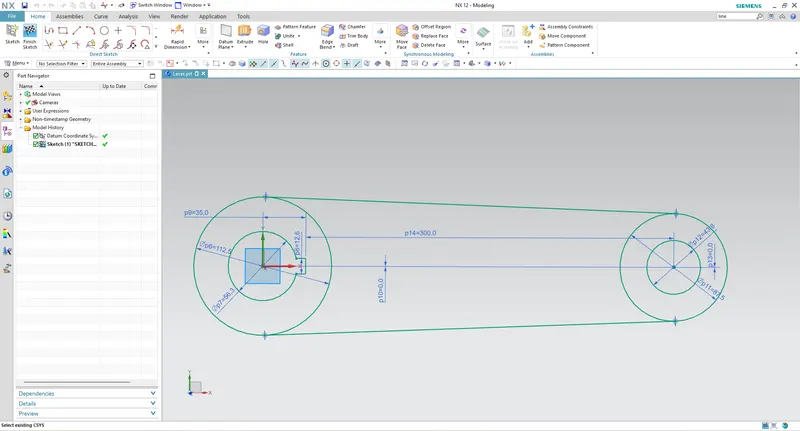
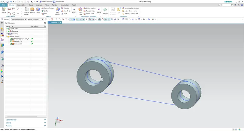
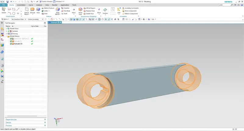
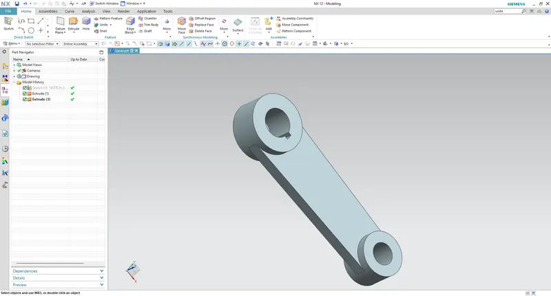
- Create two circular sketches with the appropriate diameter and specify the appropriate distance between them. Also create a keyway slot in the larger diameter sketch. Connect these two sketches with a line tangent to both circles.
- After creating a fully constrained sketch, extrude the circular region first, then the central portion with different thickness values.
- Application of GD&T:
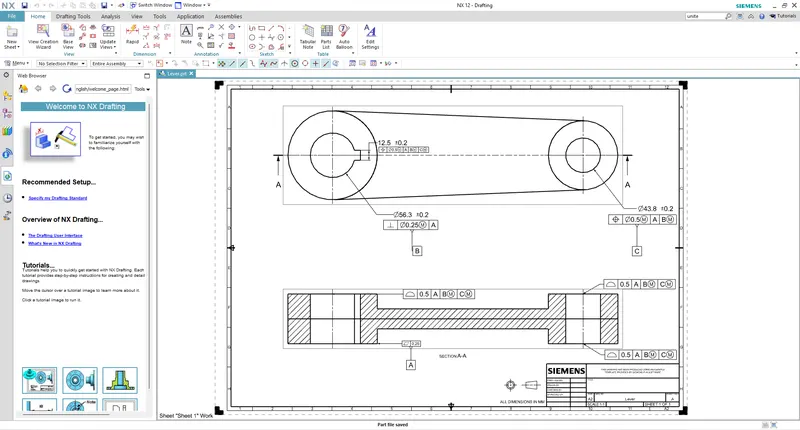
- After the lever is designed, the lever is designed for GD&T applications.
- Three datum points A, B, and C are applied to the part.
- Reference point - the underside of the lever in contact with other surfaces.
- B Reference - Applies to holes where bolts hit.
- C Datum: Applied to other holes to fully constrain the part. Finally, all other tolerances such as surface position, flatness and profile are applied to the part.
- Nut:
- Used to hold the lever and bracket together and keep the body of the butterfly valve intact.
- Create a polygonal sketch (6 sides) of appropriate dimensions. Also add a circular hole in the sketch so that you can insert the stem.
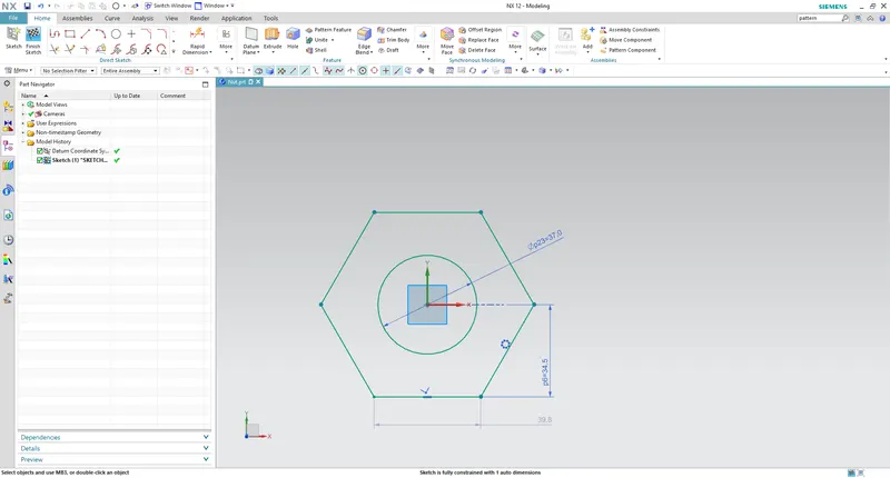
- Then Extrude the sketch using Extrude command
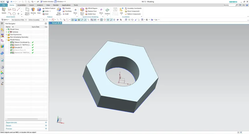
- The top of the nut is recessed for safe handling.
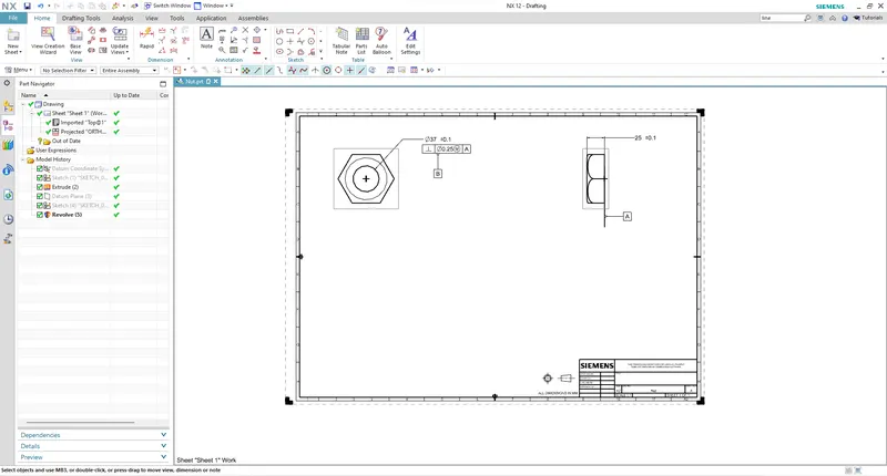
- Application of GD&T:
- Reference point A is the bottom of the nut that contacts the lever face.
- A reference point B is assigned to the hole.
- Finally, more tolerances are assigned to the nut surface and shape.
- Assembly of Butterfly Valve:
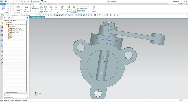
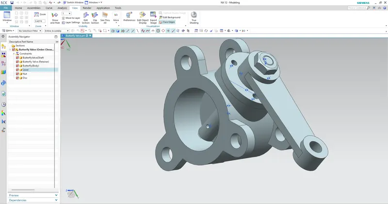
- After design, all models must be assembled under appropriate limits.
- Assemblies are created by first putting a body in place and then attaching other parts to the body using various connections provided by NX.
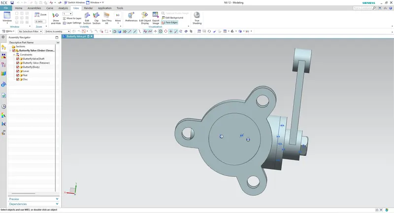
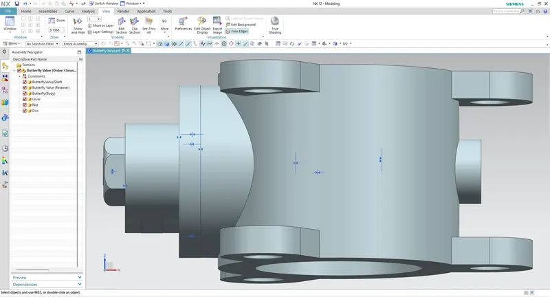
- First, The shaft & disc join together and form sub assembly which is placed in the body of the butterfly valve
- Once shaft & disc fixed in the body then add the retainer in the top of the body with the help of Assemblies constrains
- After retainer fixing then add the lever to the shaft with approperiate direction then add add the nut with top of the shaft
- Application of GD&T:
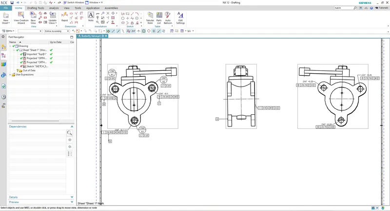
- Reference areas of interest A1, A2, A3 are assigned to the ears of the butterfly valve.
- Reference areas of interest A2 and A3 are specified with vertical and positional tolerances, respectively.
- Secondary data D is assigned to her third ear.
- Finally, other tolerances apply to the finish and function of butterfly valves.
Conclusion:
- In this project, a butterfly valve will be designed and assembled in Siemens NX parametric CAD software. GD&T based on ASME Y14.5 is applied at every stage of the part design process, making communication with manufacturers effective and efficient. Therefore, in designing this butterfly valve, the design process is performed in a true industrial manner, and the application of his GD&T, which complies with industry standards, makes the design process better understood.
- Files:
- All part files were uploaded in the same folder in the name of "Lecture 14 challenge.zip" and image also uploaded in the same folder