Week 14 challenge
First open siemens nx,click on new,click assembly and click ok.In the assemble pop up window,click the parts to add option,select all the components,orient the model correctly and click ok.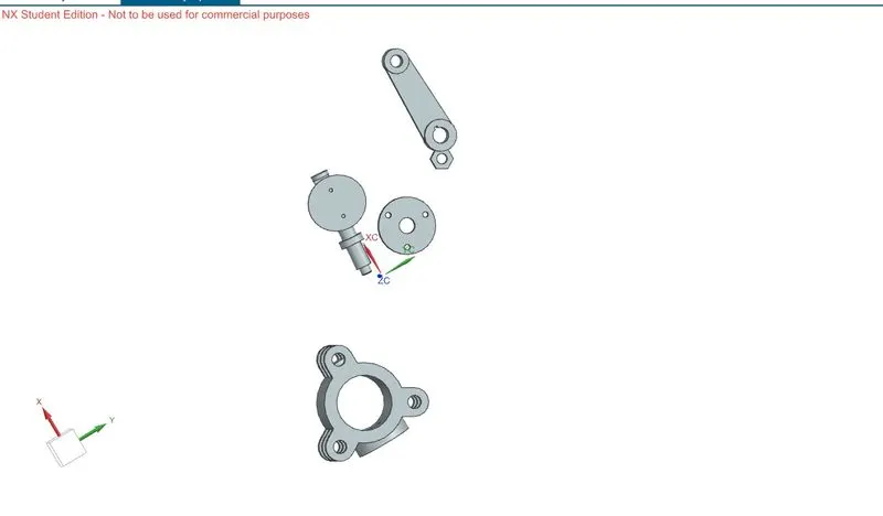
Click on move component option ,select orientation and move it using the mouse.
move the disc plate towards the shaft and align it accordingly.
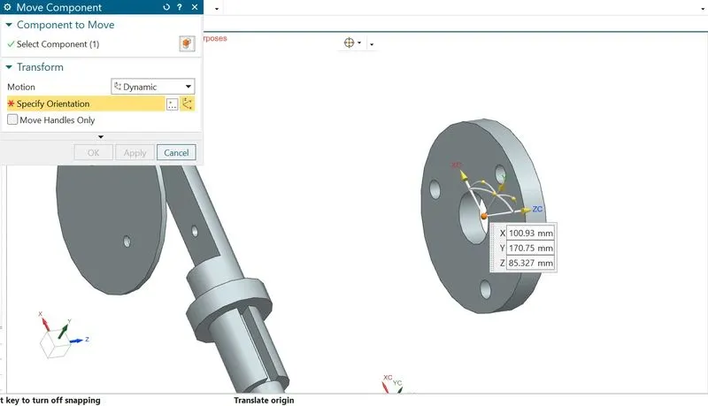
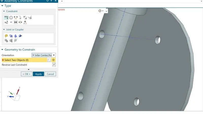
Click assembly constraints,select infer axis and select the axis of circles on both disc and the shaft and click apply.
next select touch in orientation,select the mating surface of the disc and the shaft and click ok.
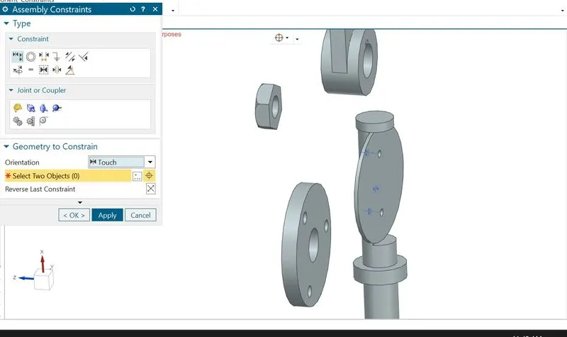
click move component and move the assembled parts into the main body
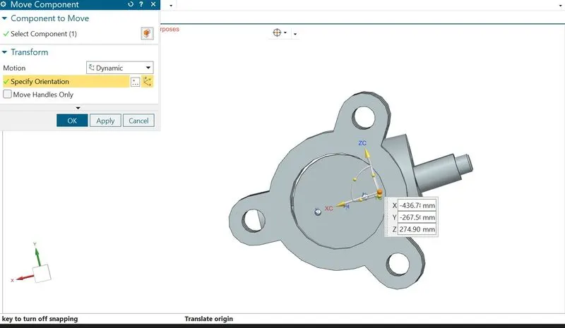
Click assembly constraints ,select infer axis and make the center of shaft and the hole center of main body concentric,click apply.next select touch in orientation,select the surface of disc and inside surface of main body and click ok.
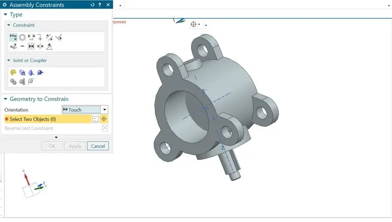
Click move component ,move the lever to top of the assembled parts ,select the orientation and align it correctly.
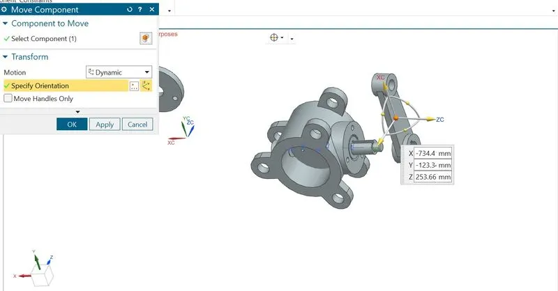
click assembly constraints,select infer axis,select the axis of hole of lever and that of center of main body,click align,select the edge of the key on both the lever and the shaft,select touch ,select the mating surface of lever and shaft and click ok.
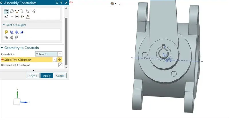
Move the retainer to the top of the main body and orient it.
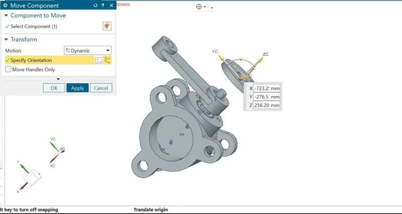
click assembly constraints,click infer axis,selec the center hole axis and axis of shaft ,click apply.select the center of hole on side and the center of side hole on the main body.select touch and touch the mating surfaces of the retainer and the main body.
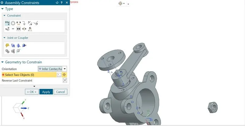
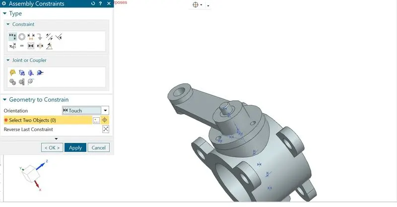
Move and orient the nut as required.
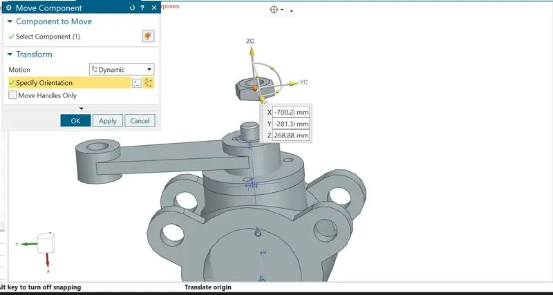
ailgn the center of nut with shaft and touch the mating surfaces.
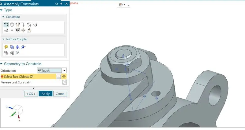
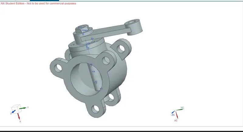
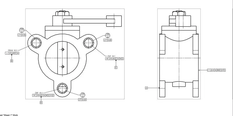
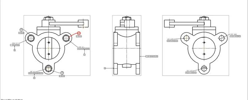
after completing the assembly,click applications,click drafting.Close the pop up windows,right click on side of the sheet,select base view ,click orientation,align it accurately and place it on suitable location.Move the mouse to get the side view and place it accordingly.Right click ,select projected view and move the mouse to place it on a suitable location.
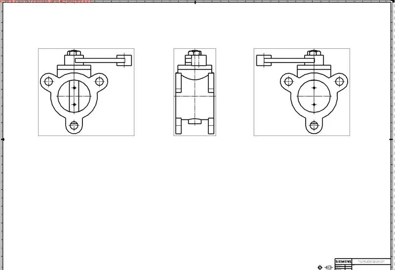
create two circles ,one overlapping and one 60 mm diameter over the hole .
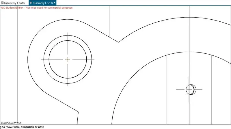
press ctrl+t to copy the created circles to the other two holes.
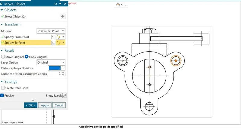
click cross hatch and select the boundary curves and click ok.
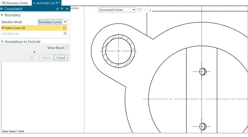
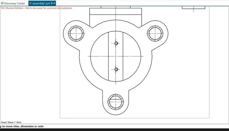
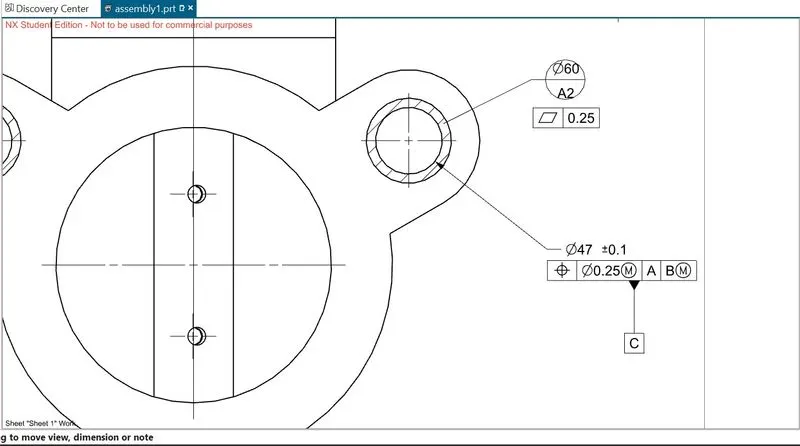
Click datum target,select the hatched area and give diamter and label it as A1.All the three hatched areas are datum target areas A1,A2 and A3.
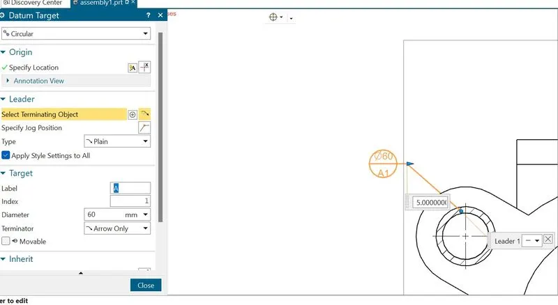
Click feature control frame,provide the geometric characteristic and give tolerance and specify location ,click ok.
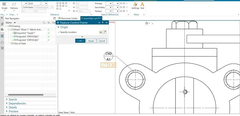
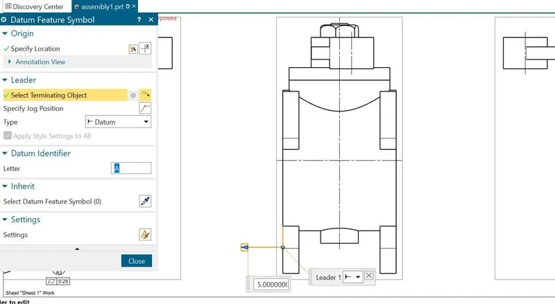
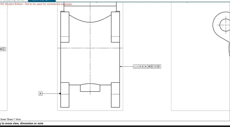
The datum targets A1,A2,A3 constitute the datum A,click datum feature symbol,give label and select the side of side view as terminating object and click ok.
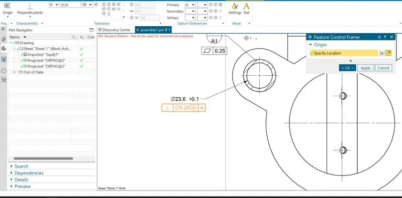
The top right hole is taken as datum B.It is given dimension using radial dimension,given bilateral tolerance.Click feature control frame and give geometric characteristic ,tolerance and datum references.click datum feature symbol,click the hole as terminating object,give label and click ok.
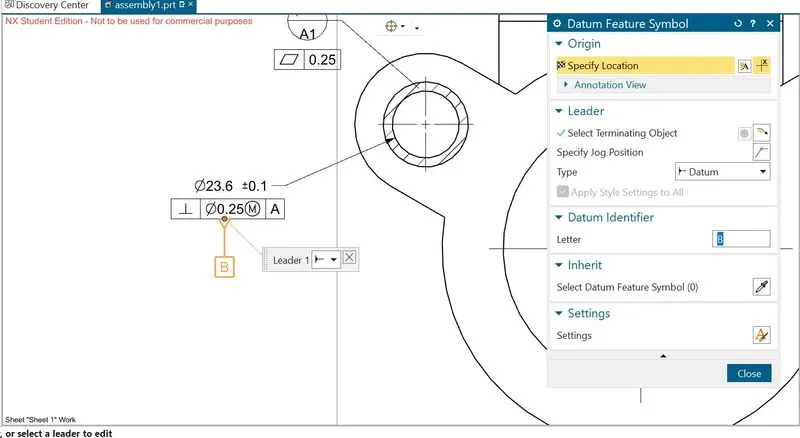
The top right hole is also given dimension using radial dimension,also feature control frame and given datum feature symbol.It is taken as Datum C.
Click feature control frame ,click the opposite surface as the terminating object in side view and give geometric characteristic,tolerance and datum references.
The bottom hole is taken as the datum D,along with giving radial dimension and feature control frame.
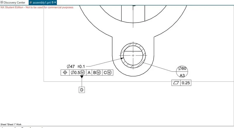
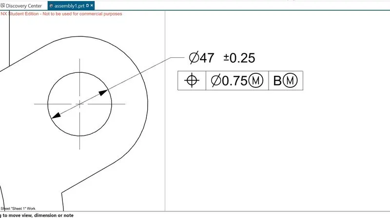
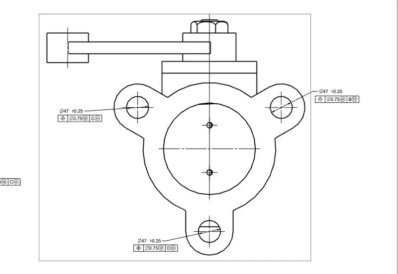
To control the tolerances of the holes on the opposite side,give dimension using radial dimension and give feature cintrol frame,and with reference to datim of hole which is in line with it. This is done for all the three holes.