Week 14 challenge
Aim:-
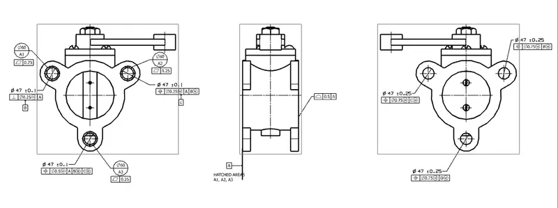
- To assemble and apply GD&T to the butterfly valve assemble drawing.
Butterfly Valve:-
- Butterfly valve which is used to allow and stop the flow of something(solid, liquid, gas). Butterfly valve is from a family of valves called QUATER TURN VALVES. This name is given by the working principle of the valve. Generally a circle will have to make 360° to make one complete circel. Unlike the butterfly valve needs to operate only 90° to either open or close. We can easily control the flow of anyting within the pipes which have butterfly valve by rotating 90° to either open or close. This is cheper than other valves, efficient working, user friendly and no need to check/clean often. This valve is used in various industries like pharmaceutical, petrol, chemical, water, gas.
GD&T:-
- The full form of GD&T is Geometric Dimensioning and Tolerancing. This gives the product as much as precise as per the GD&T given. This can be used as mode of communication over the universe between the designers from anywhere from the world. GD&T uses set of 14 symbols to interpret the information on the 2D drawing to the designer, manufacturer, quality inspector, etc., By using GD&T anyone can reduce the confusion between the designer and manufacturer, also can reduce the wastage of material that reduces the cost and can able to manufacture the part precise as per the design which is applied with GD&T. There was many standards of GD&T but now one which is used is ASME(American Society Of Mechanical Engineers) Y 14.5 which establishes symbols, definitions, and rules for geometric dimensioning and tolerancing.
Parts in Butterfly Valve:-
- Body
- Shaft
- Retainer
- Plate
- Nut
- Handle lever
- Screws
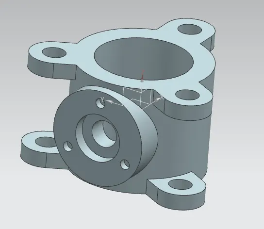
Body:-
- Body of the butterfly valve is going to connect with the two ends of the pipe. This Should be designed precisely to avoid any leakage or breakage of the valve after installing.
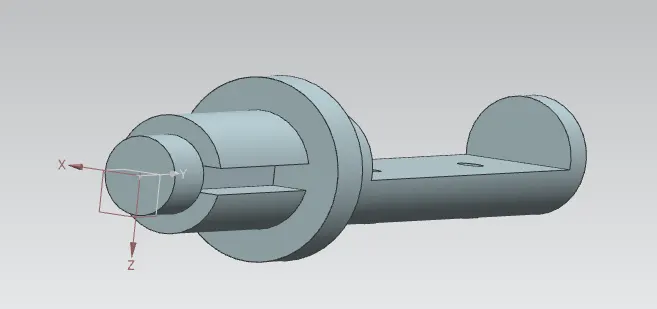
Shaft:-
- Shaft is one of the main component in the butterfly valve. The handle is attached to the shaft. The plate is going to connect with the shaft which allows or blocks the pathway.
Retainer:-
- Retainer is the plate with three sholes which is going to connect in between the top of the body and the lever. The retainer prevents the leakage of substance to the top of the valve by closing tight with the help of screws on it.
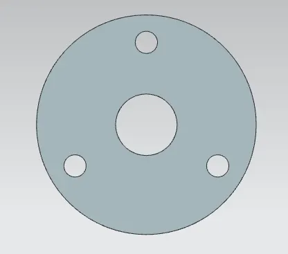
Plate:-
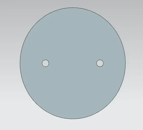
- Plate is going to fix with the shaft which block/clear the pathway by rotating the shaft connected with the lever. The plate is connected with the shaft by the screws. This should be designed very precise because if the plate didn't fits perfectly within the body then it leads to leakage and breakage of the plate.
Nut:-
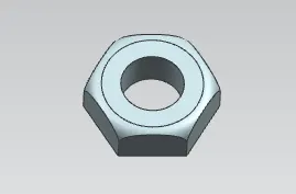
- Nut is used to tighten the lever with the shaft in place. Here the hexagonal nut is used to hold the lever in place with the shaft.
Handle lever:-
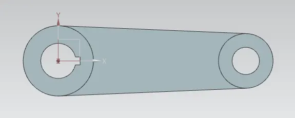
- Handle lever is used to control the flow of motion through the butterfly valve. The lever is connected to shaft which is the composite part of shaft and the plate.
Screws:-
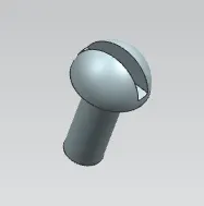
- Screws are used to fix the two component into one by screwing it by very tight. Here the screws are used in the plate and shaft, retainer and body.
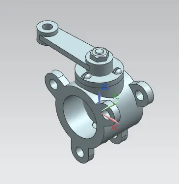
Final Assembly of Butterfly Valve:-
Isometric View:-
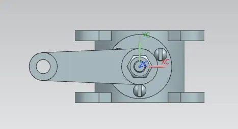
Top view:-
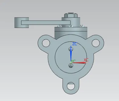
Front View:-
Applying GD&T:-
After applying GD&T to the 2D drawing of butterfly valve assembly.