Week 12 - Validation studies of Symmetry BC vs Wedge BC in OpenFOAM vs Analytical H.P equation
AIM:
To simulate the wedge flow using the OpenFOAM for different angles of the wedge and to capture the results.
The given angles for the flow are
10 Degree
25 Degree
45 Degree
OBJECTIVE:
- Writing a program in MATLAB that can generate the computational mesh automatically for any wedge angle and grading scheme.
- Show that the velocity profile is fully developed.
- Post-process velocity and shear stress.
- To validate studies of symmetry BC vs Wedge BC
THEORY:
Hagen Poiseuille’s equation:
In nonideal fluid dynamics, the Hagen–Poiseuille equation, also known as the Hagen–Poiseuille law, Poiseuille law, or Poiseuille equation, is a physical law that gives the pressure drop in an incompressible and Newtonian fluid in laminar flow flowing through a long cylindrical pipe of the constant cross-section. It can be successfully applied to airflow in lung alveoli, or the flow through a drinking straw or through a hypodermic needle.
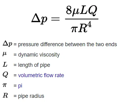
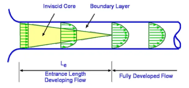
For a pipe with the laminar flow, there are basically two regions. Entrance length developing region where the flow is not fully developed and the laminar flow layers are at equal velocity with respect to each other whereas in the fully developed region the flow is fully developed and follows the Hagen – Poiseuille law.
Assumptions:
- Geometry: Axisymmetric
- Reynolds number Re: 2100 (Laminar Flow)
- Working fluid: water (Density = 998 Kg/m3)
- Fluid Temperature: 25 OC
- Dynamic Viscosity of water = 8.9e-4 Pa-s
- Theta – 4 Degree
- Calculating the diameter of the pipe (depends on Reynolds number):
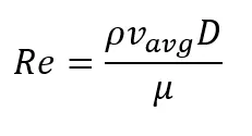
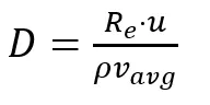
8. For calculating the total length of pipe,
Hydrodynamic Length of the pipe (Lh) = 0.05 * Re * D
Total length of the pipe (L) = Lh + 0.5
Analytical Solution:
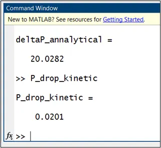
Here for solving the problem numerically we will use the icoFoam solver with the cavity tutorial to make the geometry along with the mesh and make the blockMeshDict file with the help of MATLAB as shown below.
[MATLAB CODE]
clear all
close all
clc

%% Inputs

Re = 2100;                                              % Reynolds No. as mentioned in question
theta = input('Please enter the wedge angle ');         % Angle of Sector of pipe in Degrees
V_avg = input('Please enter the average velocity ');    % Average Velocity
Nu = 1e-6;                                              % Kinematic Viscosity
rho = 998;                                              % Desity of water
V_max = 2*V_avg;                                        % Maximum velocity
mu = 8.9e-4;                                            % Dynamic viscosity of water at 25 Degree celcius
D = (Re*mu)/(rho*V_avg);                                % Diameter of pipe in meters (Calculated according to Reynold's No.)
R = D/2;                                                % Radius of pipe

% Actual Length of pipe
Lh = 0.05*Re*D;                                         % Hydrodynamic length of pipe
L = Lh + 0.5;

%% To calculate the end time of the Simulation

start_time = 0;
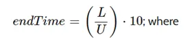
end_time = (L/V_avg);           % Time = Distance/Speed

%% Annalytical Pressure Drop
deltaP_annalytical = ((8*mu*L*V_avg)/R^2);

%% Kinetic Pressure Drop
P_drop_kinetic = deltaP_annalytical/rho;

%% Vertices creation

% Point 0:
x0 = 0;
y0 = 0;
z0 = 0;

% Point 1:
x1 = R*sind(theta/2);
y1 = R*cosd(theta/2);
z1 = 0;

% Point 2:
x2 = -R*sind(theta/2);
y2 =  R*cosd(theta/2);
z2 =  0;

% Point 3:
x3 = 0;
y3 = 0;
z3 = L;

% Point 4:
x4 = R*sind(theta/2);
y4 = R*cosd(theta/2);
z4 = L;

% Point 5:
x5 = -R*sind(theta/2);
y5 =  R*cosd(theta/2);
z5 =  L;


%% Points at Arc

% Arc 1-2
x6 = 0;
y6 = R;
z6 = 0;

% Arc 4-5
x7 = 0;
y7 = R;
z7 = L;

%% No. of cells in local Axis

nx =30;
ny = 1;
nz = 500;

%% Grading Factor

gx = 0.05;
gy = 1;
gz = 1;

%% Creating the BLOCKMESHDICT file

f1 = fopen('blockMeshDict.txt','w');

    fprintf(f1,'/*--------------------------------*- C++ -*----------------------------------*n');
    fprintf(f1,'  =========                |n');
    fprintf(f1,'        /  F ield         | OpenFOAM: The Open Source CFD Toolboxn');
    fprintf(f1,'       /   O peration     | Website:  https://openfoam.orgn');
    fprintf(f1,'      /    A nd           | Version:  8n');
    fprintf(f1,'     /     M anipulation  |n');
    fprintf(f1,'*---------------------------------------------------------------------------*/n');
    fprintf(f1,'FoamFilen');
    fprintf(f1,'{n');
    fprintf(f1,'    version     2.0;n');
    fprintf(f1,'    format      ascii;n');
    fprintf(f1,'    class       dictionary;n');
    fprintf(f1,'    object      blockMeshDict;n');
    fprintf(f1,'}n');
    fprintf(f1,'// * * * * * * * * * * * * * * * * * * * * * * * * * * * * * * * * * * * * * //nn');
    fprintf(f1,'convertToMeters 1;nn');
    fprintf(f1,'verticesn');
    fprintf(f1,'(n');
    fprintf(f1,'    (%f %f %f)  //0 n',x0,y0,z0);
    fprintf(f1,'    (%f %f %f)  //1 n',x1,y1,z1);
    fprintf(f1,'    (%f %f %f)  //2 n',x2,y2,z2);
    fprintf(f1,'    (%f %f %f)  //3 n',x3,y3,z3);
    fprintf(f1,'    (%f %f %f)  //4 n',x4,y4,z4);
    fprintf(f1,'    (%f %f %f)  //5 n',x5,y5,z5);
    fprintf(f1,');nn');
    fprintf(f1,'blocksn');
    fprintf(f1,'(n');
    fprintf(f1,'    hex (0 1 2 0 3 4 5 3) (%d %d %d) simpleGrading (%f %f %f)n',nx,ny,nz,gx,gy,gz);
    fprintf(f1,');nn');
    fprintf(f1,'edgesn');
    fprintf(f1,'(n');
    fprintf(f1,'    arc 1 2 (%d %d %d)n',x6,y6,z6);
    fprintf(f1,'    arc 4 5 (%d %d %d)n',x7,y7,z7);
    fprintf(f1,');nn');
    fprintf(f1,'boundaryn');
    fprintf(f1,'(n');
    fprintf(f1,'    inletn');
    fprintf(f1,'    {n');
    fprintf(f1,'        type patch;n        facesn');
    fprintf(f1,'        (n');
    fprintf(f1,'          (0 1 2 0)n');
    fprintf(f1,'        );n');
    fprintf(f1,'    }n');
    fprintf(f1,'    outletn');
    fprintf(f1,'    {n');
    fprintf(f1,'        type patch;n        facesn');
    fprintf(f1,'        (n');
    fprintf(f1,'          (3 5 4 3)n');
    fprintf(f1,'        );n');
    fprintf(f1,'    }n');
    fprintf(f1,'    fixedWallsn');
    fprintf(f1,'    {n');
    fprintf(f1,'        type wall;n        facesn');
    fprintf(f1,'        (n');
    fprintf(f1,'          (4 5 2 1)n');
    fprintf(f1,'        );n');
    fprintf(f1,'    }n');
    fprintf(f1,'    frontn');
    fprintf(f1,'    {n');
    fprintf(f1,'        type wedge;n        facesn');
    fprintf(f1,'        (n');
    fprintf(f1,'          (0 3 4 1)n');
    fprintf(f1,'        );n');
    fprintf(f1,'    }n');
    fprintf(f1,'    backn');
    fprintf(f1,'    {n');
    fprintf(f1,'        type wedge;n        facesn');
    fprintf(f1,'        (n');
    fprintf(f1,'          (3 0 2 5)n');
    fprintf(f1,'        );n');
    fprintf(f1,'    }n');
    fprintf(f1,'    bottomn');
    fprintf(f1,'    {n');
    fprintf(f1,'        type empty;n        facesn');
    fprintf(f1,'        (n');
    fprintf(f1,'          (0 0 3 3)n');
    fprintf(f1,'        );n');
    fprintf(f1,'    }n');
    fprintf(f1,');nn');
    fprintf(f1,'mergePatchPairsn');
    fprintf(f1,'(n');
    fprintf(f1,');nn');
    fprintf(f1,'// * * * * * * * * * * * * * * * * * * * * * * * * * * * * * * * * * * * * * //nn');

fclose(f1);
The blockMeshDict file is thus created and is then replaced with the original block mesh file in the system folder.
The created block mesh file is can be seen below:
blockMeshDict file for a wedge of angle 10 Deg:
/*--------------------------------*- C++ -*----------------------------------*
  =========                |
        /  F ield         | OpenFOAM: The Open Source CFD Toolbox
       /   O peration     | Website:  https://openfoam.org
      /    A nd           | Version:  8
     /     M anipulation  |
*---------------------------------------------------------------------------*/
FoamFile
{
    version     2.0;
    format      ascii;
    class       dictionary;
    object      blockMeshDict;
}
// * * * * * * * * * * * * * * * * * * * * * * * * * * * * * * * * * * * * * //

convertToMeters 1;

vertices
(
    (0.000000 0.000000 0.000000)  //0
    (0.000816 0.009328 0.000000)  //1
    (-0.000816 0.009328 0.000000)  //2
    (0.000000 0.000000 2.466383)  //3
    (0.000816 0.009328 2.466383)  //4
    (-0.000816 0.009328 2.466383)  //5
);

blocks
(
    hex (0 1 2 0 3 4 5 3) (30 1 500) simpleGrading (0.050000 1.000000 1.000000)
);

edges
(
    arc 1 2 (0 9.363727e-03 0)
    arc 4 5 (0 9.363727e-03 2.466383e+00)
);

boundary
(
    inlet
    {
        type patch;
        faces
        (
          (0 1 2 0)
        );
    }
    outlet
    {
        type patch;
        faces
        (
          (3 5 4 3)
        );
    }
    fixedWalls
    {
        type wall;
        faces
        (
          (4 5 2 1)
        );
    }
    front
    {
        type wedge;
        faces
        (
          (0 3 4 1)
        );
    }
    back
    {
        type wedge;
        faces
        (
          (3 0 2 5)
        );
    }
    bottom
    {
        type empty;
        faces
        (
          (0 0 3 3)
        );
    }
);

mergePatchPairs
(
);

// * * * * * * * * * * * * * * * * * * * * * * * * * * * * * * * * * * * * * //
blockMeshDict file for a wedge of angle 25 Deg:
/*--------------------------------*- C++ -*----------------------------------*
  =========                |
        /  F ield         | OpenFOAM: The Open Source CFD Toolbox
       /   O peration     | Website:  https://openfoam.org
      /    A nd           | Version:  8
     /     M anipulation  |
*---------------------------------------------------------------------------*/
FoamFile
{
    version     2.0;
    format      ascii;
    class       dictionary;
    object      blockMeshDict;
}
// * * * * * * * * * * * * * * * * * * * * * * * * * * * * * * * * * * * * * //

convertToMeters 1;

vertices
(
    (0.000000 0.000000 0.000000)  //0
    (0.002027 0.009142 0.000000)  //1
    (-0.002027 0.009142 0.000000)  //2
    (0.000000 0.000000 2.466383)  //3
    (0.002027 0.009142 2.466383)  //4
    (-0.002027 0.009142 2.466383)  //5
);

blocks
(
    hex (0 1 2 0 3 4 5 3) (30 1 500) simpleGrading (0.050000 1.000000 1.000000)
);

edges
(
    arc 1 2 (0 9.363727e-03 0)
    arc 4 5 (0 9.363727e-03 2.466383e+00)
);

boundary
(
    inlet
    {
        type patch;
        faces
        (
          (0 1 2 0)
        );
    }
    outlet
    {
        type patch;
        faces
        (
          (3 5 4 3)
        );
    }
    fixedWalls
    {
        type wall;
        faces
        (
          (4 5 2 1)
        );
    }
    front
    {
        type wedge;
        faces
        (
          (0 3 4 1)
        );
    }
    back
    {
        type wedge;
        faces
        (
          (3 0 2 5)
        );
    }
    bottom
    {
        type empty;
        faces
        (
          (0 0 3 3)
        );
    }
);

mergePatchPairs
(
);

// * * * * * * * * * * * * * * * * * * * * * * * * * * * * * * * * * * * * * //
blockMeshDict file for a wedge of angle 45 Deg:
/*--------------------------------*- C++ -*----------------------------------*
  =========                |
        /  F ield         | OpenFOAM: The Open Source CFD Toolbox
       /   O peration     | Website:  https://openfoam.org
      /    A nd           | Version:  8
     /     M anipulation  |
*---------------------------------------------------------------------------*/
FoamFile
{
    version     2.0;
    format      ascii;
    class       dictionary;
    object      blockMeshDict;
}
// * * * * * * * * * * * * * * * * * * * * * * * * * * * * * * * * * * * * * //

convertToMeters 1;

vertices
(
    (0.000000 0.000000 0.000000)  //0
    (0.003583 0.008651 0.000000)  //1
    (-0.003583 0.008651 0.000000)  //2
    (0.000000 0.000000 2.466383)  //3
    (0.003583 0.008651 2.466383)  //4
    (-0.003583 0.008651 2.466383)  //5
);

blocks
(
    hex (0 1 2 0 3 4 5 3) (30 1 500) simpleGrading (0.050000 1.000000 1.000000)
);

edges
(
    arc 1 2 (0 9.363727e-03 0)
    arc 4 5 (0 9.363727e-03 2.466383e+00)
);

boundary
(
    inlet
    {
        type patch;
        faces
        (
          (0 1 2 0)
        );
    }
    outlet
    {
        type patch;
        faces
        (
          (3 5 4 3)
        );
    }
    fixedWalls
    {
        type wall;
        faces
        (
          (4 5 2 1)
        );
    }
    front
    {
        type wedge;
        faces
        (
          (0 3 4 1)
        );
    }
    back
    {
        type wedge;
        faces
        (
          (3 0 2 5)
        );
    }
    bottom
    {
        type empty;
        faces
        (
          (0 0 3 3)
        );
    }
);

mergePatchPairs
(
);

// * * * * * * * * * * * * * * * * * * * * * * * * * * * * * * * * * * * * * //
Following is the velocity and pressure boundary condition which is been updated according to the above-mentioned details. The velocity and pressure files are present in the zero (0) folder inside the constant folder.
The velocity and pressure boundary condition are can be seen below:
Velocity (U) field files:
/*--------------------------------*- C++ -*----------------------------------*
  =========                 |
        /  F ield         | OpenFOAM: The Open Source CFD Toolbox
       /   O peration     | Website:  https://openfoam.org
      /    A nd           | Version:  8
     /     M anipulation  |
*---------------------------------------------------------------------------*/
FoamFile
{
    version     2.0;
    format      ascii;
    class       volVectorField;
    object      U;
}
// * * * * * * * * * * * * * * * * * * * * * * * * * * * * * * * * * * * * * //

dimensions      [0 1 -1 0 0 0 0];

internalField   uniform (0 0 0);

boundaryField
{
    inlet
    {
        type            fixedValue;
        value           uniform (0 0 0.1);
    }

    outlet
    {
        type            zeroGradient;
    }

    fixedWalls
    {
        type            noSlip;
    }

    front
    {
        type            wedge;
    }

    back
    {
        type            wedge;
    }

    bottom
    {
        type            empty;
    }
}

// ************************************************************************* //
Pressure (P) field files:
/*--------------------------------*- C++ -*----------------------------------*
  =========                 |
        /  F ield         | OpenFOAM: The Open Source CFD Toolbox
       /   O peration     | Website:  https://openfoam.org
      /    A nd           | Version:  8
     /     M anipulation  |
*---------------------------------------------------------------------------*/
FoamFile
{
    version     2.0;
    format      ascii;
    class       volScalarField;
    object      p;
}
// * * * * * * * * * * * * * * * * * * * * * * * * * * * * * * * * * * * * * //

dimensions      [0 2 -2 0 0 0 0];

internalField   uniform 0;

boundaryField
{
    inlet
    {
        type            zeroGradient;
    }

    outlet
    {
        type            fixedValue;
        value		 uniform 0;
    }

    fixedWalls
    {
        type            zeroGradient;
    }

    front
    {
        type            wedge;
    }

    back
    {
        type            wedge;
    }

    bottom
    {
        type            empty;
    }
}

// ************************************************************************* //
Transproperties field files:
/*--------------------------------*- C++ -*----------------------------------*
  =========                 |
        /  F ield         | OpenFOAM: The Open Source CFD Toolbox
       /   O peration     | Website:  https://openfoam.org
      /    A nd           | Version:  8
     /     M anipulation  |
*---------------------------------------------------------------------------*/
FoamFile
{
    version     2.0;
    format      ascii;
    class       dictionary;
    location    "constant";
    object      transportProperties;
}
// * * * * * * * * * * * * * * * * * * * * * * * * * * * * * * * * * * * * * //

nu              [0 2 -1 0 0 0 0] 0.000001;


// ************************************************************************* //
ControlDict file:
/*--------------------------------*- C++ -*----------------------------------*
  =========                 |
        /  F ield         | OpenFOAM: The Open Source CFD Toolbox
       /   O peration     | Website:  https://openfoam.org
      /    A nd           | Version:  8
     /     M anipulation  |
*---------------------------------------------------------------------------*/
FoamFile
{
    version     2.0;
    format      ascii;
    class       dictionary;
    location    "system";
    object      controlDict;
}
// * * * * * * * * * * * * * * * * * * * * * * * * * * * * * * * * * * * * * //

application     icoFoam;

startFrom       startTime;

startTime       0;

stopAt          endTime;

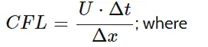
endTime         50;

deltaT          0.001;

writeControl    timeStep;

writeInterval   20;

purgeWrite      0;

writeFormat     ascii;

writePrecision  6;

writeCompression off;

timeFormat      general;

timePrecision   6;

runTimeModifiable true;


// ************************************************************************* //
The end time and the deltaT values were calculated by the courant number formula.
After putting all these values, the simulation was run and the following results were obtained:
For 10 Deg Wedge BC:
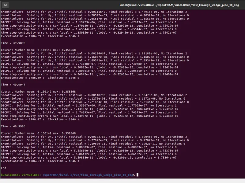
Simulation Time – 50 sec
Execution time – 1786.53 sec
For 10 Deg Symmetry BC:
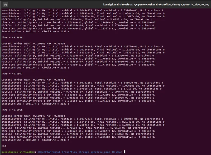
Simulation Time – 50 sec
Execution time – 2061.86 sec
For 25 Deg Wedge BC:
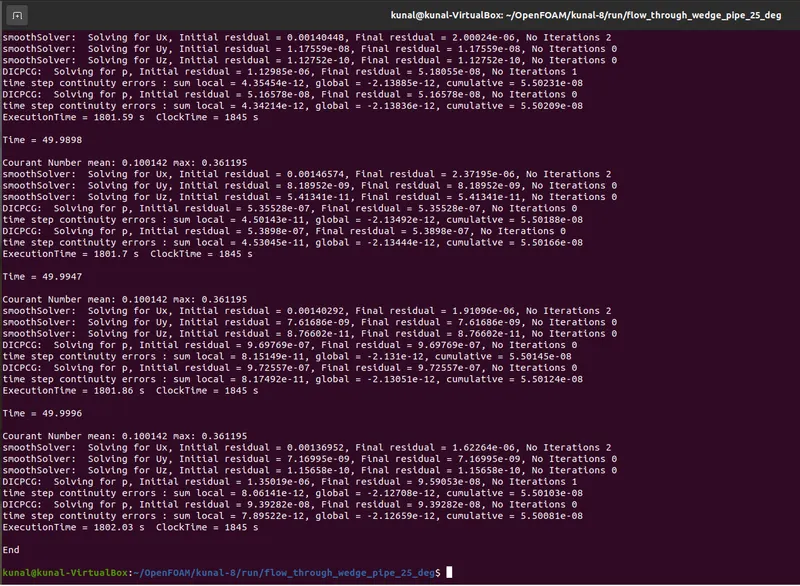
Simulation Time – 50 sec
Execution time – 1802.03 sec
For 25 Deg Symmetry BC:
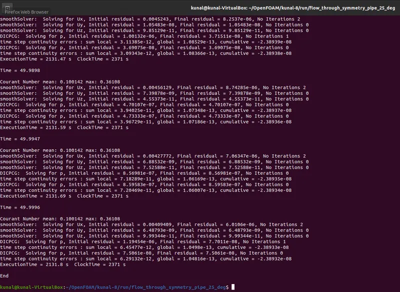
Simulation Time – 50 sec
Execution time – 2131.8 sec
For 45 Deg Wedge BC:
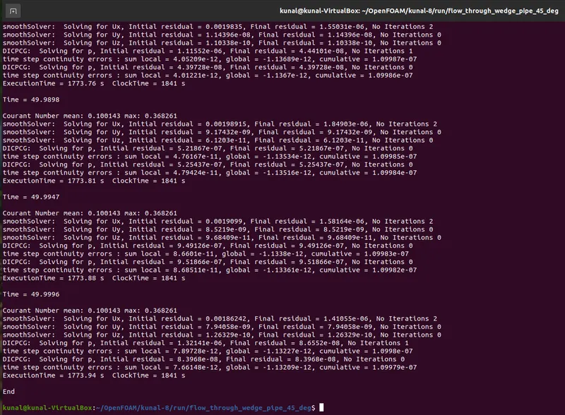
Simulation Time – 50 sec
Execution time – 1773.94 sec
For 45 Deg Symmetry BC:
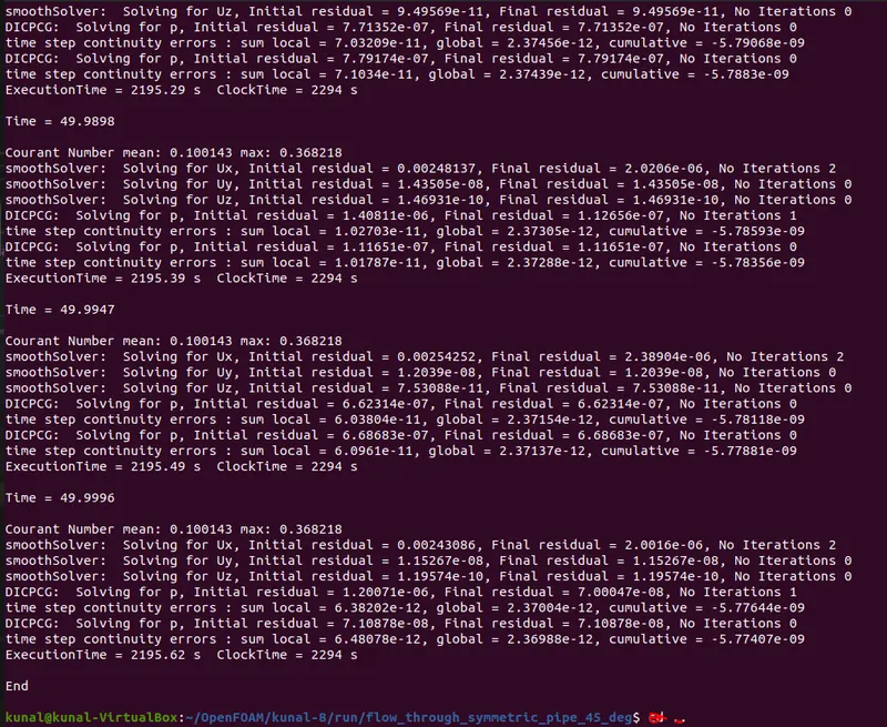
Simulation Time – 50 sec
Execution time – 2195.62 sec
RESULTS:
For 10 Deg Wedge/Symmetry BC:
The created geometry can thus be seen in the figure below with a wedge angle of 10 Degree:
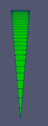
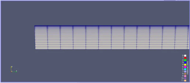
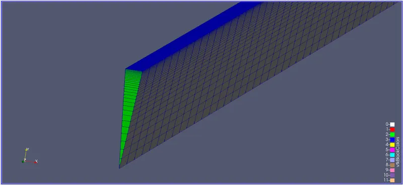
After the simulation the pressure and velocity at the entrance and exit of the pipe are shown below:
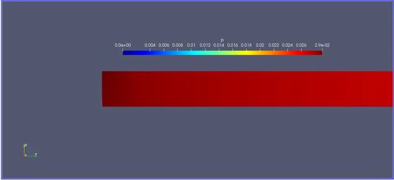
Fig: Pressure at the entrance of the pipe
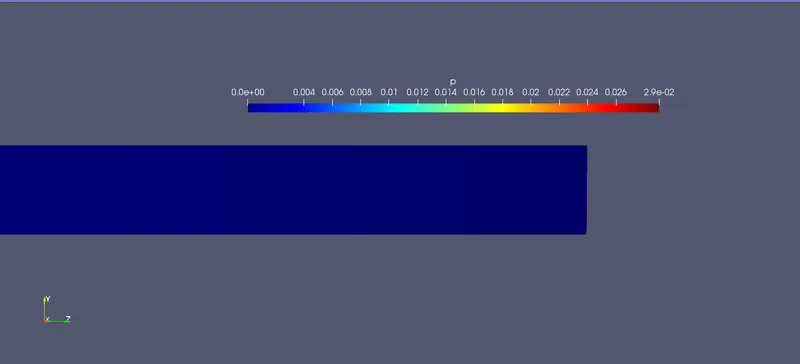
Fig: Pressure at the exit of the pipe
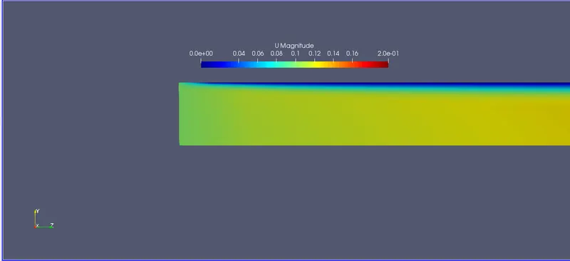
Fig: Velocity at the entrance of the pipe
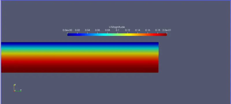
Fig: Velocity at the exit of the pipe
As these contour plots give very little explanation about the results, the plot over line command is used to get the line graph of velocity and pressure contour.
The graphs are shown below:
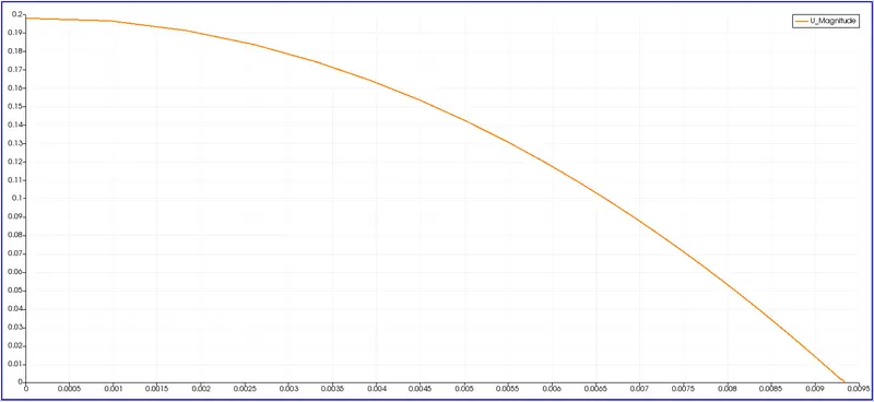
Fig: Velocity Plot for 10 Deg Wedge Fig: Velocity Plot for 10 Deg Symmetry
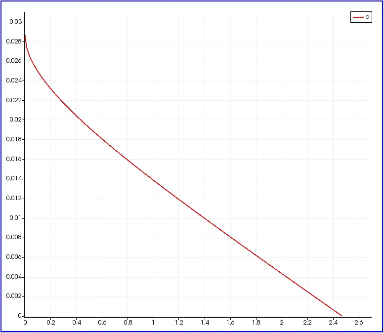
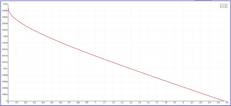
Fig: Pressure Plot for 10 Deg Wedge Fig: Pressure Plot for 10 Deg Symmetry
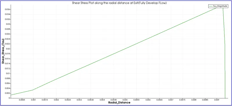
Fig: Shear stress Plot for 10 Deg Wedge Fig: Shear Stress Plot for 10 Deg Symmetry
For 25 Deg Wedge/Symmetry BC:
The created geometry can thus be seen in the figure below with a wedge angle of 25 Degree:
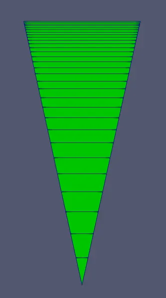
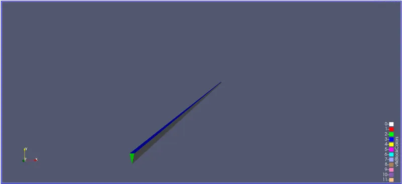
After the simulation the pressure and velocity at the entrance and exit of the pipe are shown below:
Fig: Pressure at the entrance of the pipe
Fig: Pressure at the exit of the pipe
Fig: Velocity at the entrance of the pipe
Fig: Velocity at the exit of the pipe
As these contour plots give very little explanation about the results, the plot over line command is used to get the line graph of velocity and pressure contour.
The graphs are shown below:
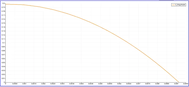
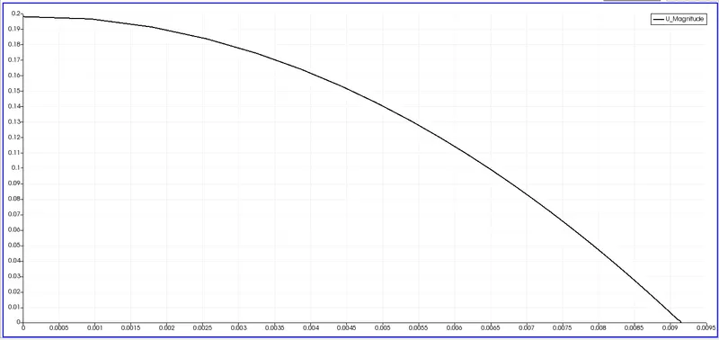
Fig: Velocity Plot for 25 Deg Wedge Fig: Velocity Plot for 25 Deg Symmetry
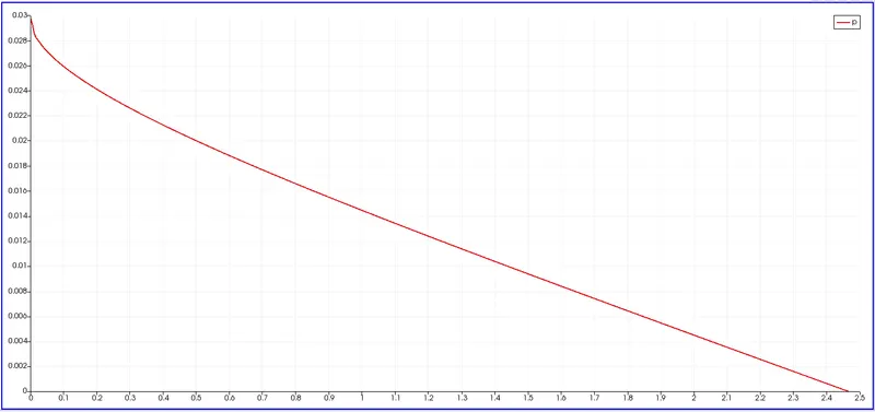
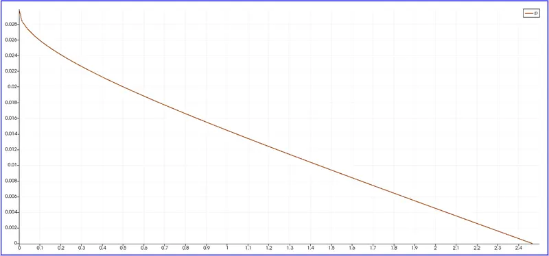
Fig: Pressure Plot for 25 Deg Wedge Fig: Pressure Plot for 25 Deg Symmetry
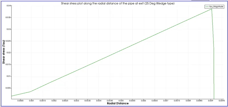
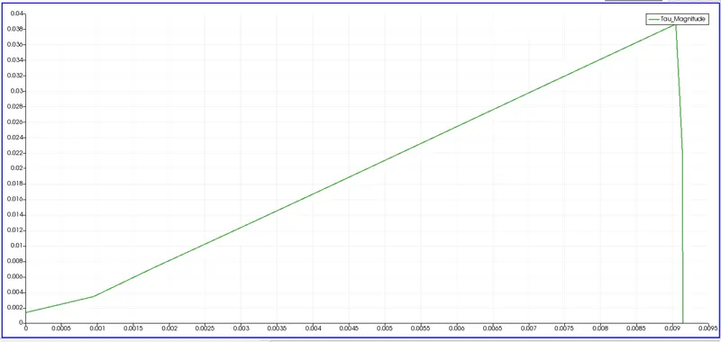
Fig: Shear stress Plot for 25 Deg Wedge Fig: Shear Stress Plot for 25 Deg Symmetry
For 45 Deg Wedge/Symmetry BC:
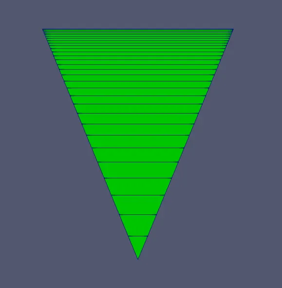
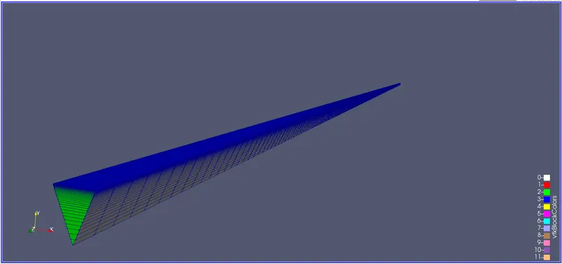
The created geometry can thus be seen in the figure below with a wedge angle of 45 Degree:
After the simulation the pressure and velocity at the entrance and exit of the pipe are shown below:
Fig: Pressure at the entrance of the pipe
Fig: Pressure at the exit of the pipe
Fig: Velocity at the entrance of the pipe
Fig: Velocity at the exit of the pipe
As these contour plots give very little explanation about the results, the plot over line command is used to get the line graph of velocity and pressure contour.
The graphs are shown below:

Fig: Velocity Plot for 45 Deg Wedge Fig: Velocity Plot for 45 Deg Symmetry
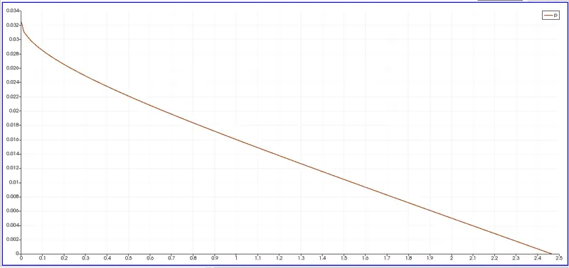
Fig: Pressure Plot for 45 Deg Wedge Fig: Pressure Plot for 45 Deg Symmetry
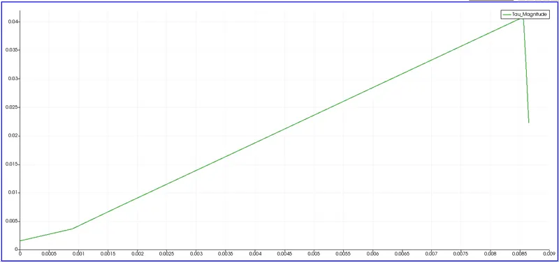
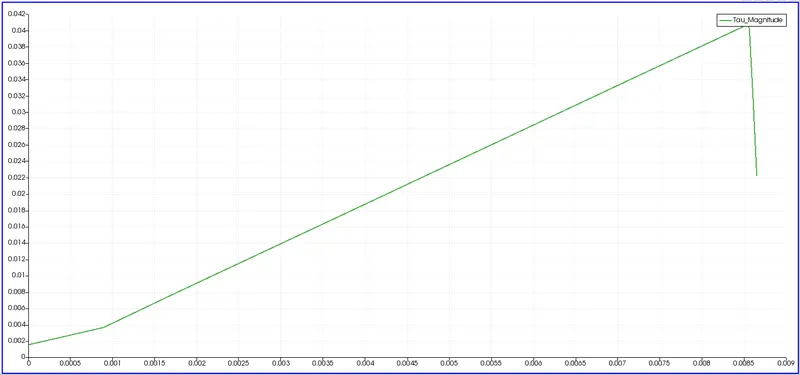
Fig: Shear stress Plot for 45 Deg Wedge Fig: Shear Stress Plot for 45 Deg Symmetry
DISCUSSION AND CONCLUSSION:
The below table gives a detailed explanation of the pressure, velocity, and shear stress results that were obtained during performing the simulation for wedge and symmetric boundary conditions:
|
Wedge Angle(Deg) |
Constraints Type |
Execution Time [s] |
Maximum Velocity [m/s^-1] |
Pressure Drop [m^2.s^-2] |
|
10 |
Wedge |
1786.53 |
0.197978 |
0.0287648 |
|
10 |
Symmetry |
2061.86 |
0.197975 |
0.0287648 |
|
25 |
Wedge |
1802.03 |
0.198099 |
0.0297066 |
|
25 |
Symmetry |
2131.8 |
0.19810 |
0.0297081 |
|
45 |
Wedge |
1773.94 |
0.198356 |
0.0324881 |
|
45 |
Symmetry |
2195.62 |
0.198356 | 0.0324881 |
- The numerical simulation of flow through a cut section of the pipe geometry using the wedge and symmetry boundary condition for wedge angles of 10, 25, and 45 Degrees in OpenFOAM was well understood.
- It was realized that while the maximum velocity computed using symmetry boundary condition showed better correlation with increasing wedge angles, wedge constraint type for wedge angle of 4 deg done in the previous project demonstrates the closest prediction when compared to the analytical values.
- Additionally, the wedge boundary condition is most effective when the wedge angle is less than 5 degrees.