Validation studies of Symmetry BC vs Wedge BC for laminar pipe flow in OpenFOAM vs Analytical H.P equation
Part 2: Validation studies of Symmetry BC vs Wedge BC in OpenFOAM vs Analytical H.P equation
This part of the project is a continuation to the project:
https://skill-lync.com/projects/week-11-simulation-of-flow-through-a-pipe-in-openfoam-129
Problem Statement:
Perform simulation for the below-mentioned angles using both symmetry and wedge boundary conditions and validate them with HP equations for the laminar pipe flow.
Angles to test:
- `10^o`
- `25^o`
- `45^o`
In this project the above mentioned angles were used as wedge angles and symmetry palnes angles for the Laminar pipe flow.
The geometry of the pipe considered , fluid used, boundary conditions are similar to part 1 of the project.
The computational grid considered for both wedge and symmetry type boundary conditions are as follows:
| Number of cells (axial,radial,tangential) |
Grading Factor (axial,radial,tangential) |
||||
|
|
Analysis using Wedge type boundary conditions:
The wedge type BC analysis is similar to part 1, instead, the angles 10 deg, 25 deg, and 45 deg are considered here. The blockDict file , controlDict file, transport properties file, boundary condition files of U and p for the wedge angle 45 deg case are shown below:
blockDict file:
/*---------------------------------------*- C++ -*-----------------------------------------*
  =========                     |
  \      /  F ield             | OpenFOAM: The Open Source CFD Toolbox
   \    /   O peration         | Website:  https://openfoam.org
    \  /    A nd               | version:  8
     \/     M anipulation      |
*---------------------------------------*- C++ -*-----------------------------------------*/
FoamFile
{
    version    2.0;
    format     ascii;
    class      dictionary;
    object     blockMeshDict;
}
//* * * * * * * * * * * * * * * * * * * * //

convertToMeters 0.001;

vertices
(
  (0 0 0)      //0-vertex at inlet_center_point
  (0 2.309699e+00 9.567086e-01)      //1-second vertex at inlet
  (0 2.309699e+00 -9.567086e-01)      //2-third vertex at inlet
  (1000 0 0)      //3-vertex at outlet_center_point
  (1000 2.309699e+00 9.567086e-01)      //4-second vertex at outlet
  (1000 2.309699e+00 -9.567086e-01)      //5-third vertex at inlet
);
edges
(
  arc 2 1 45 (1 0 0)   // inlet arc from vertex 1 to vertex 2,4 degrees, y-normal
  arc 5 4 45 (1 0 0)   // outlet arc from vertex 4 to vertex 5, 4 degrees, y-normal
);
blocks
(
  hex (0 2 1 0 3 5 4 3) (40 1 500) simpleGrading (1.000000e-01 1 1)  // wedge
);
boundary
(
      inlet  // inlet boundary
{
      type patch;
      faces
      (
      (0 2 1 0)
      );
}
      outlet  // outlet boundary
{
      type patch;
      faces
      (
      (3 5 4 3)
      );
}
      noslipwall  // wall boundary
{
      type noSlip;
      faces
      (
      (1 2 5 4)
      );
}
      wedge1  // wedge
{
      type wedge;
      faces
      (
      (0 1 4 3)
      );
}
      wedge2  // wedge
{
      type wedge;
      faces
      (
      (0 2 5 3)
      );
}
      axis  // centerline
{
      type empty;
      faces
      (
      (0 3 3 0)
      );
}
);
mergePatchPairs   // merging matching faces
(
);

//************************************************//
ControlDict file:
/*--------------------------------*- C++ -*----------------------------------*
  =========                 |
  \      /  F ield         | OpenFOAM: The Open Source CFD Toolbox
   \    /   O peration     | Website:  https://openfoam.org
    \  /    A nd           | Version:  8
     \/     M anipulation  |
*---------------------------------------------------------------------------*/
FoamFile
{
    version     2.0;
    format      ascii;
    class       dictionary;
    location    "system";
    object      controlDict;
}
// * * * * * * * * * * * * * * * * * * * * * * * * * * * * * * * * * * * * * //

application     icoFoam;

startFrom       startTime;

startTime       0;

stopAt          endTime;

endTime         3;

deltaT          0.001488;

writeControl    timeStep;

writeInterval   20;

purgeWrite      0;

writeFormat     ascii;

writePrecision  6;

writeCompression off;

timeFormat      general;

timePrecision   6;

runTimeModifiable true;


// ************************************************************************* //
Transport properties:
/*--------------------------------*- C++ -*----------------------------------*
  =========                 |
  \      /  F ield         | OpenFOAM: The Open Source CFD Toolbox
   \    /   O peration     | Website:  https://openfoam.org
    \  /    A nd           | Version:  8
     \/     M anipulation  |
*---------------------------------------------------------------------------*/
FoamFile
{
    version     2.0;
    format      ascii;
    class       dictionary;
    location    "constant";
    object      transportProperties;
}
// * * * * * * * * * * * * * * * * * * * * * * * * * * * * * * * * * * * * * //

nu              [0 2 -1 0 0 0 0] 7.978e-7;


// ************************************************************************* //
Velocity BC:
/*--------------------------------*- C++ -*----------------------------------*
  =========                 |
  \      /  F ield         | OpenFOAM: The Open Source CFD Toolbox
   \    /   O peration     | Website:  https://openfoam.org
    \  /    A nd           | Version:  8
     \/     M anipulation  |
*---------------------------------------------------------------------------*/
FoamFile
{
    version     2.0;
    format      ascii;
    class       volVectorField;
    object      U;
}
// * * * * * * * * * * * * * * * * * * * * * * * * * * * * * * * * * * * * * //

dimensions      [0 1 -1 0 0 0 0];

internalField   uniform (0 0 0);

boundaryField
{
    inlet
    {
        type            fixedValue;
        value           uniform (0.336 0 0);
    }

    noslipwall
    {
        type            noSlip;
    }
    wedge1
    {
    	type 		 wedge;
    }
    wedge2
    {
    	type 		 wedge;
    }
    axis
    {
    	type 		 empty;
    }
    outlet
    {
        type            zeroGradient;
    }
}

// ************************************************************************* //
Pressure BC:
/*--------------------------------*- C++ -*----------------------------------*
  =========                 |
  \      /  F ield         | OpenFOAM: The Open Source CFD Toolbox
   \    /   O peration     | Website:  https://openfoam.org
    \  /    A nd           | Version:  8
     \/     M anipulation  |
*---------------------------------------------------------------------------*/
FoamFile
{
    version     2.0;
    format      ascii;
    class       volScalarField;
    object      p;
}
// * * * * * * * * * * * * * * * * * * * * * * * * * * * * * * * * * * * * * //

dimensions      [0 2 -2 0 0 0 0];

internalField   uniform 0;

boundaryField
{
    inlet
    {
        type            zeroGradient;
    }

    noslipwall
    {
        type            zeroGradient;
    }
    wedge1
    {
    	type 		 wedge;
    }
    wedge2
    {
    	type 		 wedge;
    }
    axis
    {
    	type 		 empty;
    }
    outlet
    {
        type            fixedValue;
        value		 uniform 0.12695;
    }
}

// ************************************************************************* //
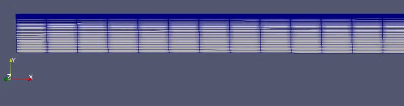
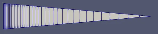
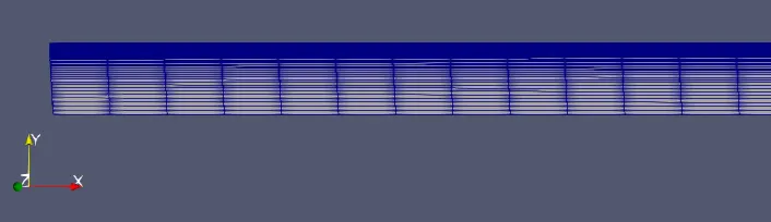
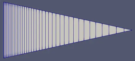
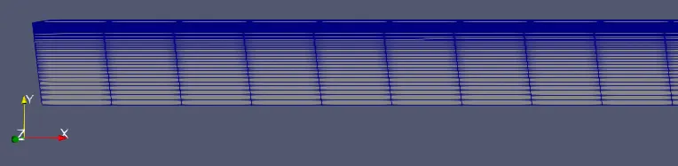
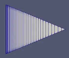
The meshes generated by executing the blockMesh command and viewing in paraview using paraFoam command are shown below:
Wede angle 10 deg:
| Axial direction of the pipe | Cross section view |
 |
 |
Wede angle 25 deg:
| Axial direction of the pipe | Cross section view |
 |
 |
Wede angle 45 deg:
| Axial direction of the pipe | Cross section view |
 |
 |
Results:
Velocity profile variation along the pipe length:
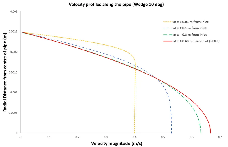
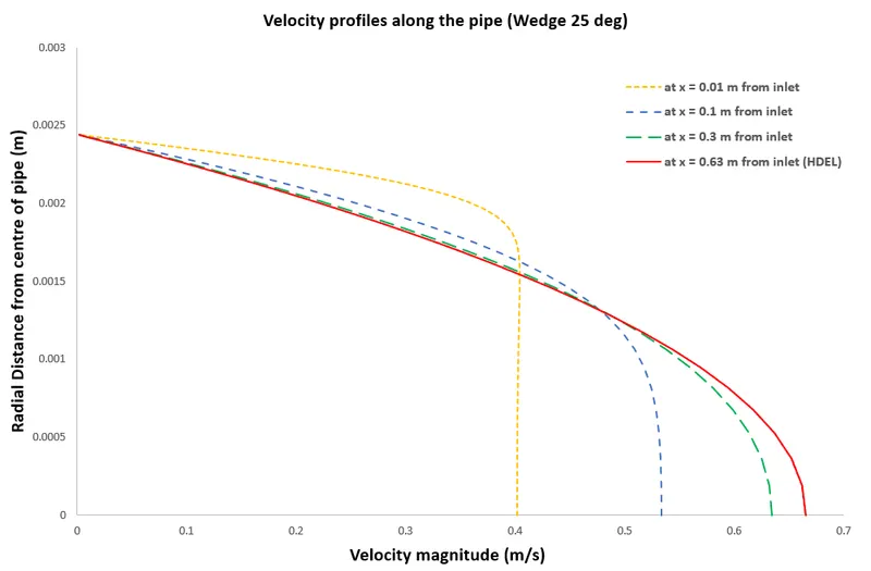
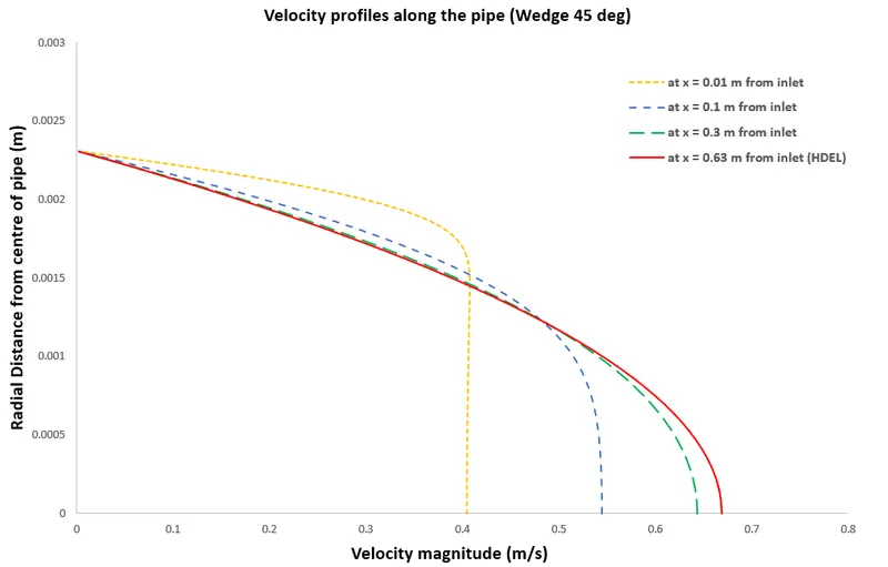
From the above figures, it is inferred that although the velocity profiles are similar at each cross-section across the pipe length, as the wedge angle increases the physics near the wall is not accurately captured.
This is because using the wedge-type boundaries, it is possible to have only one element along the tangential direction. This leads to the mesh elements not properly represent the curvature of the pipe wall.
The wedge angle should be less than 10 deg if 2d axisymmetric BC is used to properly simulate the flow
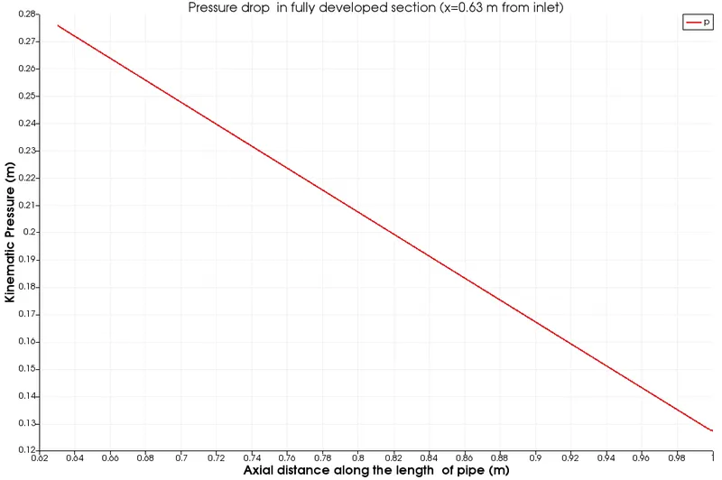
Pressure drop in the fully developed section:
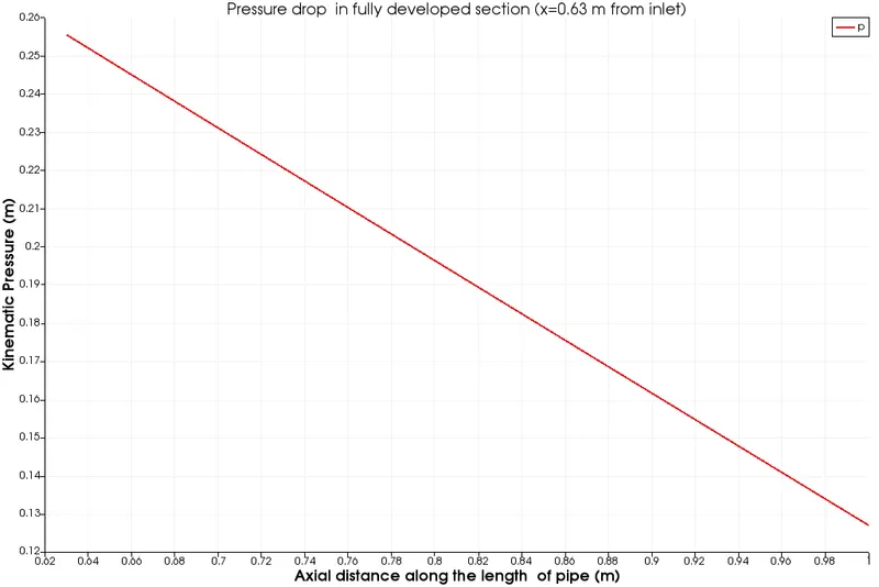
1. Wedge 10 deg:
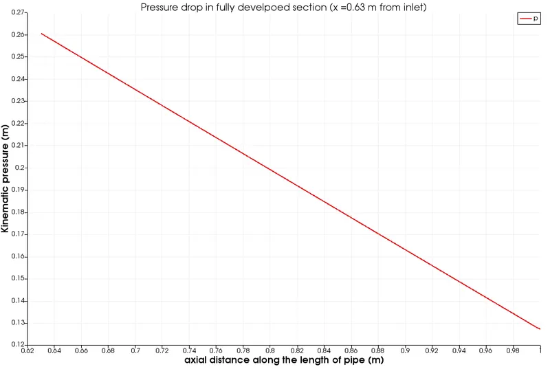
2. Wedge 25 deg:
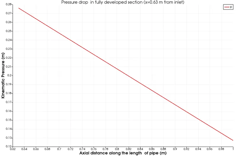
3. Wedge 45 deg:
Analysis using Symmetry type boundary conditions:
The analysis with symmetry type BC is similar to wedge-type BC analysis. The mesh is used similar to the wedge type BC analysis, to have a comparison. The difference is only in representing the wedge faces with symmetry plane BC.
The blockDict file , boundary condition files of U and p for the symmetry type BC for 45 deg case are shown below:
BlockDict file
/*---------------------------------------*- C++ -*-----------------------------------------*
  =========                     |
  \      /  F ield             | OpenFOAM: The Open Source CFD Toolbox
   \    /   O peration         | Website:  https://openfoam.org
    \  /    A nd               | version:  8
     \/     M anipulation      |
*---------------------------------------*- C++ -*-----------------------------------------*/
FoamFile
{
    version    2.0;
    format     ascii;
    class      dictionary;
    object     blockMeshDict;
}
//* * * * * * * * * * * * * * * * * * * * //

convertToMeters 0.001;

vertices
(
  (0 0 0)      //0-vertex at inlet_center_point
  (0 2.309699e+00 9.567086e-01)      //1-second vertex at inlet
  (0 2.309699e+00 -9.567086e-01)      //2-third vertex at inlet
  (1000 0 0)      //3-vertex at outlet_center_point
  (1000 2.309699e+00 9.567086e-01)      //4-second vertex at outlet
  (1000 2.309699e+00 -9.567086e-01)      //5-third vertex at inlet
);
edges
(
  arc 2 1 45 (1 0 0)   // inlet arc from vertex 1 to vertex 2,4 degrees, y-normal
  arc 5 4 45 (1 0 0)   // outlet arc from vertex 4 to vertex 5, 4 degrees, y-normal
);
blocks
(
  hex (0 2 1 0 3 5 4 3) (40 1 500) simpleGrading (1.000000e-01 1 1)  // wedge
);
boundary
(
      inlet  // inlet boundary
{
      type patch;
      faces
      (
      (0 2 1 0)
      );
}
      outlet  // outlet boundary
{
      type patch;
      faces
      (
      (3 5 4 3)
      );
}
      noslipwall  // wall boundary
{
      type noSlip;
      faces
      (
      (1 2 5 4)
      );
}
 symplane1  // symmetryplane
{
      type symmetryPlane;
      faces
      (
      (0 1 4 3)
      );
}
     symplane2  // symmetryplane
{
      type symmetryPlane;
      faces
      (
      (0 2 5 3)
      );
}
      axis  // centerline
{
      type empty;
      faces
      (
      (0 3 3 0)
      );
}
);
mergePatchPairs   // merging matching faces
(
);

//************************************************//
Velocity BC:
/*--------------------------------*- C++ -*----------------------------------*
  =========                 |
  \      /  F ield         | OpenFOAM: The Open Source CFD Toolbox
   \    /   O peration     | Website:  https://openfoam.org
    \  /    A nd           | Version:  8
     \/     M anipulation  |
*---------------------------------------------------------------------------*/
FoamFile
{
    version     2.0;
    format      ascii;
    class       volVectorField;
    object      U;
}
// * * * * * * * * * * * * * * * * * * * * * * * * * * * * * * * * * * * * * //

dimensions      [0 1 -1 0 0 0 0];

internalField   uniform (0 0 0);

boundaryField
{
    inlet
    {
        type            fixedValue;
        value           uniform (0.336 0 0);
    }

    noslipwall
    {
        type            noSlip;
    }
    symplane1
    {
    	type 		 symmetryPlane;
    }
    symplane2
    {
    	type 		 symmetryPlane;
    }
    axis
    {
    	type 		 empty;
    }
    outlet
    {
        type            zeroGradient;
    }
}

// ************************************************************************* //
Pressure BC:
/*--------------------------------*- C++ -*----------------------------------*
  =========                 |
  \      /  F ield         | OpenFOAM: The Open Source CFD Toolbox
   \    /   O peration     | Website:  https://openfoam.org
    \  /    A nd           | Version:  8
     \/     M anipulation  |
*---------------------------------------------------------------------------*/
FoamFile
{
    version     2.0;
    format      ascii;
    class       volScalarField;
    object      p;
}
// * * * * * * * * * * * * * * * * * * * * * * * * * * * * * * * * * * * * * //

dimensions      [0 2 -2 0 0 0 0];

internalField   uniform 0;

boundaryField
{
    inlet
    {
        type            zeroGradient;
    }

    noslipwall
    {
        type            zeroGradient;
    }
    symplane1
    {
    	type 		 symmetryPlane;
    }
    symplane2
    {
    	type 		 symmetryPlane;
    }
    axis
    {
    	type 		 empty;
    }
    outlet
    {
        type            fixedValue;
        value		 uniform 0.12695;
    }
}

// ************************************************************************* //
45o">Results:
45o"> Velocity profile variation along the pipe length:
45o">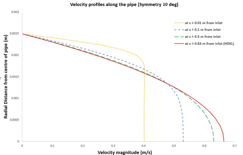
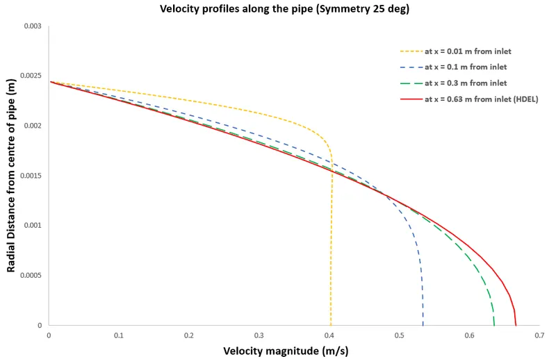
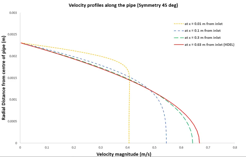
45o">From the above figures, it is inferred that although the velocity profiles are similar to the wedge type BC at each cross-section across the pipe length, as the symmetry angle increases the physics near the wall is not accurately captured.
45o">This is because using only one element along the tangential direction. This leads to the mesh elements not properly represent the curvature of the pipe wall. Increasing the number of cells above one along tangential direction may accurately capture the near wall physics.
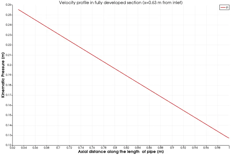
Pressure drop in the fully developed section:
1. symmetry 10 deg:
2. symmetry 25 deg:
3. symmetry 45 deg:
Validation of Numerical results:
| Analytical results (Hagen-Poiseiulle equations) | Numerical results | error (%) | |||||||||||
| Parameter | Wedge BC - 10 deg | Wedge BC - 25 deg | Wedge BC - 45 deg | Symmetry BC - 10 deg | Symmetry BC - 25 deg | Symmetry BC - 45 deg | Wedge BC - 10 deg | Wedge BC - 25 deg | Wedge BC - 45 deg | Symmetry BC - 10 deg | Symmetry BC - 25 deg | Symmetry BC - 45 deg | |
| Max Velocity (m/s) | 0.672 | 0.671 | 0.669 | 0.666 | 0.669 | 0.668 | 0.667 | 0.148 | 0.446 | 0.892 | 0.446 | 0.595 | 0.744 |
| Pressure drop (Pa) | 126.95 | 127.1 | 133 | 147 | 130 | 128 | 148 | 0.181 | 4.765 | 15.793 | 2.402 | 0.827 | 16.5 |
| Wall Shear stress | 0.427 | 0.423 | 0.418 | 0.412 | 0.424 | 0.418 | 0.413 | 0.936 | 2.10 | 3.512 | 0.702 | 3.512 | 3.278 |
Conclusion:
It can be seen from the above table that, the effect of wedge type boundary condition on the maximum velocity in the fully developed profile is negligible, but near the walls, as the wedge angle increases the curvature of the geometry is not accurately captured which leads to error in predicting near-wall physics like wall shear stress. The effect of a single cell in the tangential direction in wedge type BC limits its usage to wedge angles lesser than 10 deg, precisely less than 5 deg for 2D axisymmetric problems.
The symmetry boundary condition also shows similar results. The error in the results of the symmetry boundary condition can be reduced by using more cells in the tangential direction. Here only one cell is used in this analysis to compare results of wedge BC with symmetry BC.