Week 12 - Validation studies of Symmetry BC vs Wedge BC in OpenFOAM vs Analytical H.P equation
AIM:-
To compare between the numerical results obtained for incompressible, laminar pipe flow using OpenFOAM with the wedge and symmetry boundary conditions and also to compare the results with the analytical results based on the Hagen-Poiseulle equation. The numerical simulation is done for portions/wedges of the pipe with the following angles:
- 10
- 25
- 45
1) WEDGE TYPE
1.1 CODE:-
The OpenFOAM simulation is done using the icoFoam solver
For the 45-degree wedge type:
The blockMeshDict file
/*--------------------------------*- C++ -*----------------------------------*\
  =========                 |
  \      /  F ield         | OpenFOAM: The Open Source CFD Toolbox
   \    /   O peration     | Website:  https://openfoam.org
    \  /    A nd           | Version:  8
     \/     M anipulation  |
\*---------------------------------------------------------------------------*/
FoamFile
{
    version     2.0;
    format      ascii;
    class       dictionary;
    object      blockMeshDict;
}
// * * * * * * * * * * * * * * * * * * * * * * * * * * * * * * * * * * * * * //

convertToMeters 1;
vertices
(
    (0 0 0) // point 0
    (9.238795e-03 3.826834e-03 0) // point 1
    (9.238795e-03 3.826834e-03 3) // point 2
    (0 0 3) // point 3
    (9.238795e-03 -3.826834e-03 0) // point 4
    (9.238795e-03 -3.826834e-03 3) // point 5

);

blocks
(
    hex (0 4 1 0 3 5 2 3) (100 1 600) simpleGrading (5.000000e-01 1 1)

);

edges
(
    arc 1 4 (1.000000e-02 0 0)
    arc 2 5 (1.000000e-02 0 3)

);

boundary
(
    Inlet
    {
        type patch;
        faces
        (
            (0 4 1 0)
        );
    }
    Outlet
    {
        type patch;
        faces
        (
            (3 2 5 3)
        );
    }
    Axis
    {
        type empty;
        faces
        (
            (0 3 3 0)
        );
    }
    Wall
    {
        type wall;
        faces
        (
            (4 5 2 1)
        );
    }
    Wedge_Side_Left
    {
        type wedge;
        faces
        (
            (0 1 2 3)
        );
    }
    Wedge_Side_Right
    {
        type wedge;
        faces
        (
            (0 3 5 4)
        );
    }

);
mergePatchPairs
(
);

// ************************************************************************* //
The controlDict file
/*--------------------------------*- C++ -*----------------------------------*\
  =========                 |
  \\      /  F ield         | OpenFOAM: The Open Source CFD Toolbox
   \\    /   O peration     | Website:  https://openfoam.org
    \\  /    A nd           | Version:  8
     \\/     M anipulation  |
\*---------------------------------------------------------------------------*/
FoamFile
{
    version     2.0;
    format      ascii;
    class       dictionary;
    location    "system";
    object      controlDict;
}
// * * * * * * * * * * * * * * * * * * * * * * * * * * * * * * * * * * * * * //

application     icoFoam;

startFrom       startTime;

startTime       0;

stopAt          endTime;

endTime         15;

deltaT          0.01;

writeControl    timeStep;

writeInterval   20;

purgeWrite      0;

writeFormat     ascii;

writePrecision  6;

writeCompression off;

timeFormat      general;

timePrecision   6;

runTimeModifiable true;


// ************************************************************************* //
The initial conditions
The p file
/*--------------------------------*- C++ -*----------------------------------*\
  =========                 |
  \\      /  F ield         | OpenFOAM: The Open Source CFD Toolbox
   \\    /   O peration     | Website:  https://openfoam.org
    \\  /    A nd           | Version:  8
     \\/     M anipulation  |
\*---------------------------------------------------------------------------*/
FoamFile
{
    version     2.0;
    format      ascii;
    class       volScalarField;
    object      p;
}
// * * * * * * * * * * * * * * * * * * * * * * * * * * * * * * * * * * * * * //

dimensions      [0 2 -2 0 0 0 0];

internalField   uniform 0;

boundaryField
{
    Inlet
    {
        type            zeroGradient;
    }

    Outlet
    {
        type            fixedValue;
        value		 uniform 0;

    }

    Axis
    {
        type            empty;
    }

    Wall
    {
        type            zeroGradient;
    }

    Wedge_Side_Left
    {
        type            wedge;
    }
    Wedge_Side_Right
    {
        type            wedge;
    }
}

// ************************************************************************* //
The U file
Sets the initial velocity at time t = 0 at the inlet.
/*--------------------------------*- C++ -*----------------------------------*\
  =========                 |
  \\      /  F ield         | OpenFOAM: The Open Source CFD Toolbox
   \\    /   O peration     | Website:  https://openfoam.org
    \\  /    A nd           | Version:  8
     \\/     M anipulation  |
\*---------------------------------------------------------------------------*/
FoamFile
{
    version     2.0;
    format      ascii;
    class       volVectorField;
    object      U;
}
// * * * * * * * * * * * * * * * * * * * * * * * * * * * * * * * * * * * * * //

dimensions      [0 1 -1 0 0 0 0];

internalField   uniform (0 0 0);

boundaryField
{
    Inlet
    {
        type            fixedValue;
        value           uniform (0 0 0.0937);
    }

    Outlet
    {
        type            zeroGradient;
    }

    Wall
    {
        type            noSlip;
    }

    Wedge_Side_Left
    {
        type            wedge;
    }

    Wedge_Side_Right
    {
        type            wedge;
    }

    Axis
    {
        type            empty;
    }
}

// ************************************************************************* //
The transportProperties file
This stores the value of the shear stress coefficient (nu).
/*--------------------------------*- C++ -*----------------------------------*\
  =========                 |
  \\      /  F ield         | OpenFOAM: The Open Source CFD Toolbox
   \\    /   O peration     | Website:  https://openfoam.org
    \\  /    A nd           | Version:  8
     \\/     M anipulation  |
\*---------------------------------------------------------------------------*/
FoamFile
{
    version     2.0;
    format      ascii;
    class       dictionary;
    location    "constant";
    object      transportProperties;
}
// * * * * * * * * * * * * * * * * * * * * * * * * * * * * * * * * * * * * * //

nu              [0 2 -1 0 0 0 0] 0.892678e-6;


// ************************************************************************* //
1.2 GENERATED MESHES & VELOCITY CONTOURS
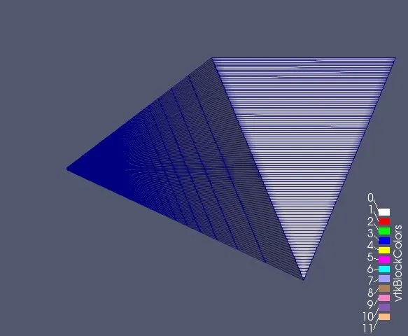
1.2.1 For`45^circ`
1.2.1.1 MESH
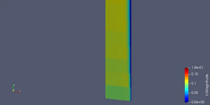
1.2.1.2 VELOCITY CONTOURS
INLET
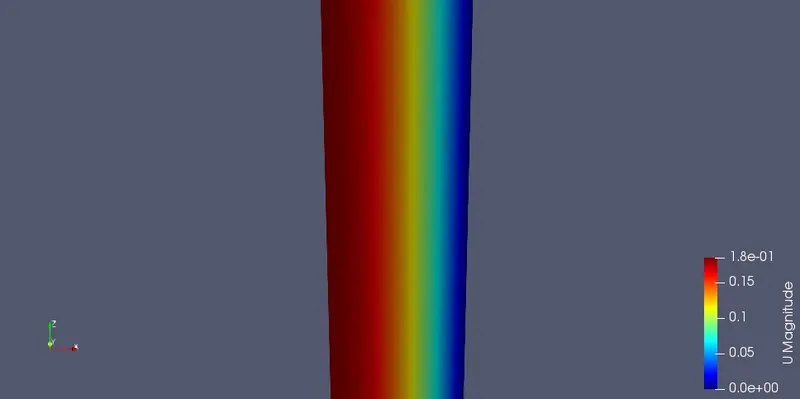
MID-POINT
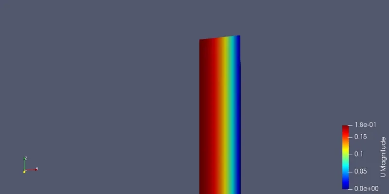
OUTLET
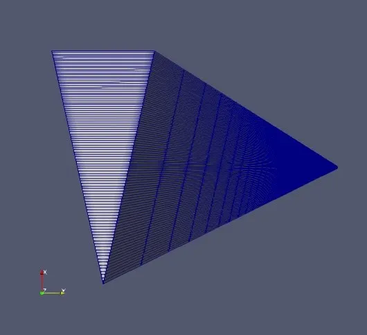
1.2.2 For`25^circ`
1.2.2.1 MESH
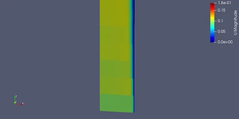
1.2.2.2 VELOCITY CONTOURS
INLET
MID-POINT
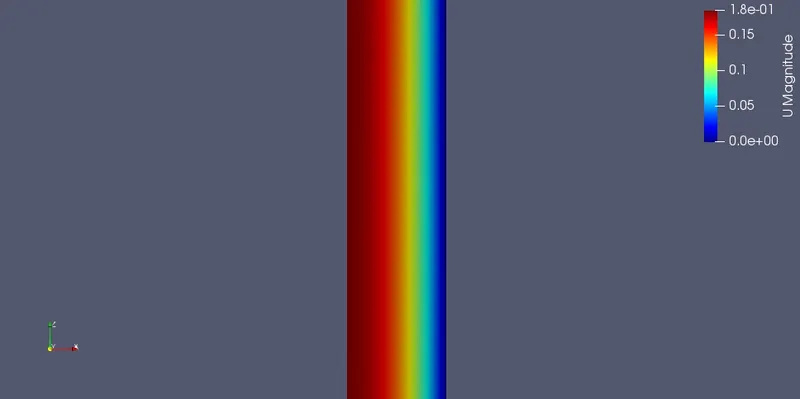
OUTLET
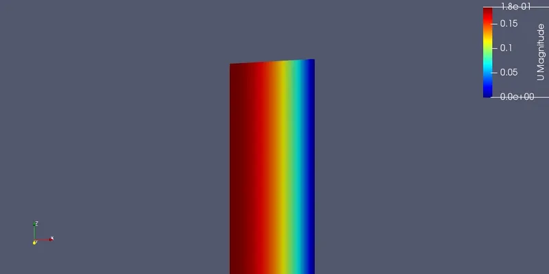
1.2.3 For`10^circ`
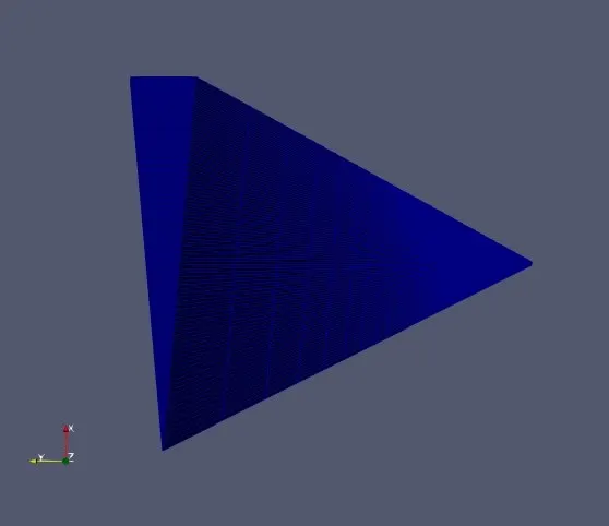
1.2.3.1 MESH
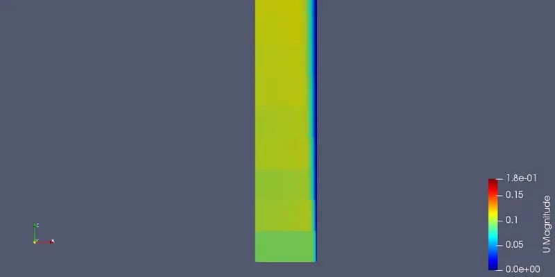
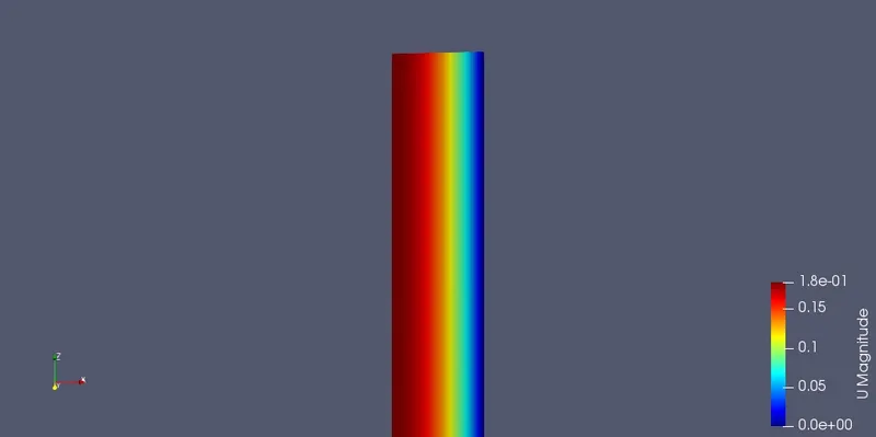
1.2.3.2 VELOCITY CONTOURS
INLET
MID-POINT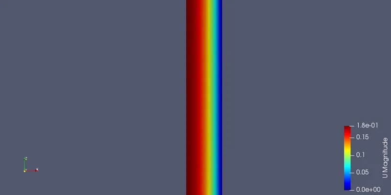
OUTLET
1.3 VELOCITY & SHEAR STRESS PROFILES AT DIFFERENT SECTIONS
CODE FOR PLOTTING VELOCITY AND SHEAR PROFILES
clear all
close all
clc

%To plot the velocity profile near inlet (at x = 0.5)
data = csvread('radial_0.5_10s.csv',1,0);
data2 = csvread('radial_0.5_25s.csv',1,0);
data3 = csvread('radial_0.5_45s.csv',1,0);
mag_U_1 = data(:,10);
mag_U_1(isnan(mag_U_1))=0;
mag_u_1 = sort(mag_U_1);
mag_U_1 = vertcat(mag_u_1,mag_U_1);

mag_U_2 = data2(:,7);
mag_U_2(isnan(mag_U_2))=0;
mag_u_2 = sort(mag_U_2);
mag_U_2 = vertcat(mag_u_2,mag_U_2);

mag_U_3 = data3(:,7);
mag_U_3(isnan(mag_U_3))=0;
mag_u_3 = sort(mag_U_3);
mag_U_3 = vertcat(mag_u_3,mag_U_3);

arc_length_1 = data(:,13);


%For the reflected section
ref_arc_length = -1.*arc_length_1;
ref_arc_length = sort(ref_arc_length);
arc_length = vertcat(ref_arc_length,arc_length_1);

origin = zeros(1,20);
y = linspace(0,0.20,20);

figure(1)
plot(arc_length,mag_U_1,'linewidth',1,'color','r');
hold on
plot(arc_length,mag_U_2,'linewidth',1,'color','b');
plot(arc_length,mag_U_3,'linewidth',1,'color','g');
plot(origin,y,'-.','linewidth',1.2,'color','k');
axis([-0.01 0.01 0 0.20])
legend('10\circ symmetry BC','25\circ symmetry BC','45\circ symmetry BC','Axisymmetric Line');
xlabel('Distance from the Axis (m)');
ylabel('Velocity (m/s)');
title('Velocity Profile at x = 0.5 m');

%For shear stress profiles
%At x = 0.5
tau_1 = data(:,17);
tau_1f = flip(tau_1);
tau_1 = vertcat(tau_1f,tau_1);

tau_2 = data2(:,9);
tau_2f = flip(tau_2);
tau_2 = vertcat(tau_2f,tau_2);

tau_3 = data3(:,9);
tau_3f = flip(tau_3);
tau_3 = vertcat(tau_3f,tau_3);

figure (2)
plot(arc_length,tau_1,'linewidth',1,'color','r');
hold on
plot(arc_length,tau_2,'linewidth',1,'color','b');
plot(arc_length,tau_3,'linewidth',1,'color','g');
plot(origin,linspace(-0.04,0.01,20),'-.','linewidth',1.2,'color','k');
axis([-0.01 0.01 -0.04 0.01])
legend('10\circ symmetry BC','25\circ symmetry BC','45\circ symmetry BC','Axisymmetric Line');
xlabel('Distance from the Axis (m)');
ylabel('Shear Stress (N/m^2)');
title('Shear Stress @ Under-Developed Cross-Section');


%To plot the fully developed velocity profile (x = 2.75)
data = csvread('radial2.75_10w.csv',1,0);
data2 = csvread('2.75_25w.csv',1,0);
data3 = csvread('radial_2.75w.csv',1,0);
mag_U_1 = data(:,7);
mag_U_1(isnan(mag_U_1))=0;
mag_u_1 = sort(mag_U_1);
mag_U_1 = vertcat(mag_u_1,mag_U_1);


mag_U_2 = data2(:,7);
mag_U_2(isnan(mag_U_2))=0;
mag_u_2 = sort(mag_U_2);
mag_U_2 = vertcat(mag_u_2,mag_U_2);

mag_U_3 = data3(:,7);
mag_U_3(isnan(mag_U_3))=0;
mag_u_3 = sort(mag_U_3);
mag_U_3 = vertcat(mag_u_3,mag_U_3);

arc_length_1 = data(:,13);


%For the reflected section
ref_arc_length = -1.*arc_length_1;
ref_arc_length = sort(ref_arc_length);
arc_length = vertcat(ref_arc_length,arc_length_1);

origin = zeros(1,20);
y = linspace(0,0.20,20);

figure(3)
plot(arc_length,mag_U_1,'linewidth',1,'color','r');
hold on
plot(arc_length,mag_U_2,'linewidth',1,'color','b');
plot(arc_length,mag_U_3,'linewidth',1,'color','g');
plot(origin,y,'-.','linewidth',1.2,'color','k');
axis([-0.01 0.01 0 0.20])
legend('10\circ symmetry BC','25\circ symmetry BC','45\circ symmetry BC','Axisymmetric Line');
xlabel('Distance from the Axis (m)');
ylabel('Velocity (m/s)');
title('Velocity Profile at x = 2.75 m');

%For shear stress profiles
%At x = 2.75
tau_1 = data(:,9);
tau_1f = flip(tau_1);
tau_1 = vertcat(tau_1f,tau_1);

tau_2 = data2(:,9);
tau_2f = flip(tau_2);
tau_2 = vertcat(tau_2f,tau_2);

tau_3 = data3(:,9);
tau_3f = flip(tau_3);
tau_3 = vertcat(tau_3f,tau_3);

figure (4)
plot(arc_length,tau_1,'linewidth',1,'color','r');
hold on
plot(arc_length,tau_2,'linewidth',1,'color','b');
plot(arc_length,tau_3,'linewidth',1,'color','g');
plot(origin,linspace(-0.035,0.01,20),'-.','linewidth',1.2,'color','k');
axis([-0.01 0.01 -0.035 0.01])
legend('10\circ symmetry BC','25\circ symmetry BC','45\circ symmetry BC','Axisymmetric Line');
xlabel('Distance from the Axis (m)');
ylabel('Shear Stress (N/m^2)');
title('Shear Stress @ Fully Developed Cross-Section');
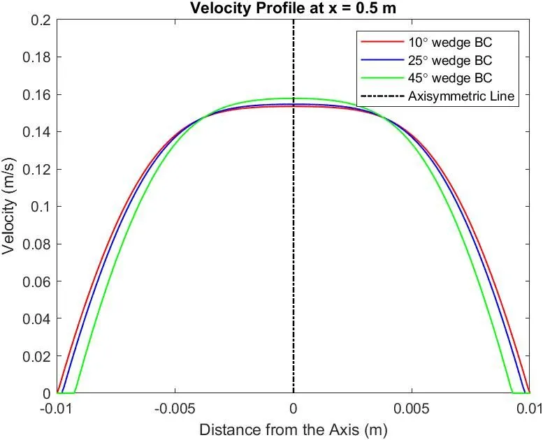
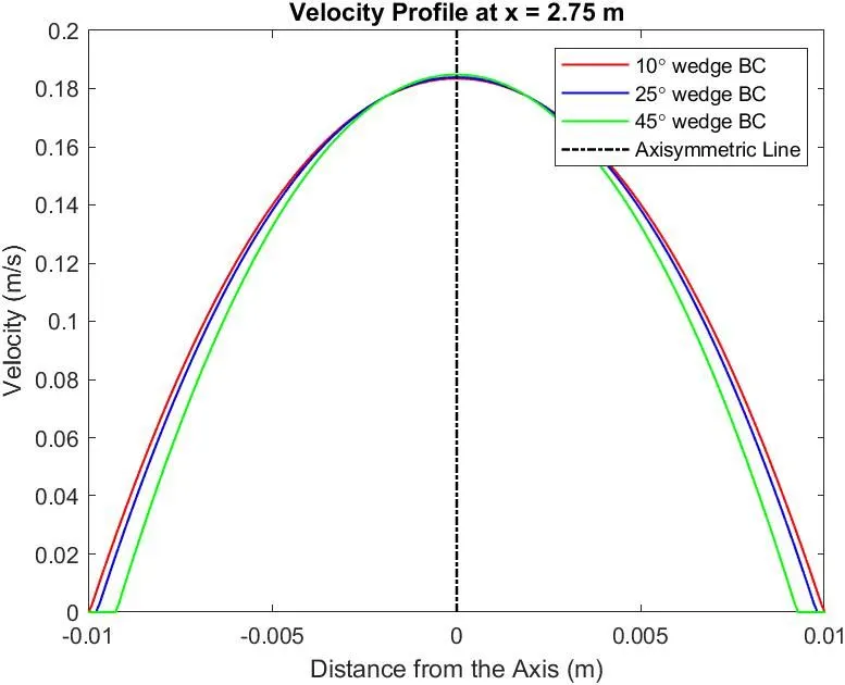
1.3.1 Velocity Profiles
At x = 0.5 (Start of Flow/Under-developed flow)
At x = 2.75 (Fully-developed flow)
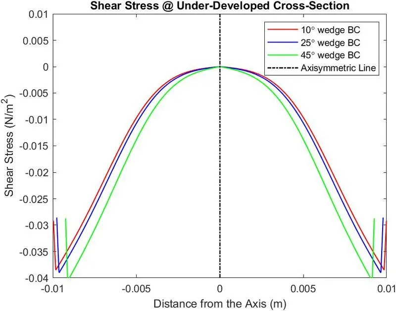
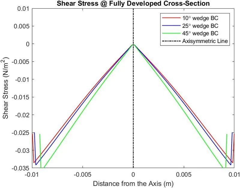
1.3.2 Shear Stress (Tau) Profiles
At x = 0.5 (Under-developed flow)
At x = 2.75 (Fully-developed flow)
2) SYMMETRY BOUNDARY TYPE
2.1 CODE:-
The OpenFOAM simulation is done using the icoFoam solver.
For the 45-degree symmetry type:
/*--------------------------------*- C++ -*----------------------------------*\
  =========                 |
  \      /  F ield         | OpenFOAM: The Open Source CFD Toolbox
   \    /   O peration     | Website:  https://openfoam.org
    \  /    A nd           | Version:  8
     \/     M anipulation  |
\*---------------------------------------------------------------------------*/
FoamFile
{
    version     2.0;
    format      ascii;
    class       dictionary;
    object      blockMeshDict;
}
// * * * * * * * * * * * * * * * * * * * * * * * * * * * * * * * * * * * * * //

convertToMeters 1;
vertices
(
    (0 0 0) // point 0
    (9.238795e-03 3.826834e-03 0) // point 1
    (9.238795e-03 3.826834e-03 3) // point 2
    (0 0 3) // point 3
    (9.238795e-03 -3.826834e-03 0) // point 4
    (9.238795e-03 -3.826834e-03 3) // point 5

);

blocks
(
    hex (0 4 1 0 3 5 2 3) (100 1 600) simpleGrading (5.000000e-01 1 1)

);

edges
(
    arc 1 4 (1.000000e-02 0 0)
    arc 2 5 (1.000000e-02 0 3)

);

boundary
(
    Inlet
    {
        type patch;
        faces
        (
            (0 4 1 0)
        );
    }
    Outlet
    {
        type patch;
        faces
        (
            (3 2 5 3)
        );
    }
    Axis
    {
        type empty;
        faces
        (
            (0 3 3 0)
        );
    }
    Wall
    {
        type wall;
        faces
        (
            (4 5 2 1)
        );
    }
    Wedge_Side_Left
    {
        type symmetry;
        faces
        (
            (0 1 2 3)
        );
    }
    Wedge_Side_Right
    {
        type symmetry;
        faces
        (
            (0 3 5 4)
        );
    }

);
mergePatchPairs
(
);

// ************************************************************************* //
The Initial Conditions
U file
/*--------------------------------*- C++ -*----------------------------------*\
  =========                 |
  \\      /  F ield         | OpenFOAM: The Open Source CFD Toolbox
   \\    /   O peration     | Website:  https://openfoam.org
    \\  /    A nd           | Version:  8
     \\/     M anipulation  |
\*---------------------------------------------------------------------------*/
FoamFile
{
    version     2.0;
    format      ascii;
    class       volVectorField;
    object      U;
}
// * * * * * * * * * * * * * * * * * * * * * * * * * * * * * * * * * * * * * //

dimensions      [0 1 -1 0 0 0 0];

internalField   uniform (0 0 0);

boundaryField
{
    Inlet
    {
        type            fixedValue;
        value           uniform (0 0 0.0937);
    }

    Outlet
    {
        type            zeroGradient;
    }

    Wall
    {
        type            noSlip;
    }

    Wedge_Side_Left
    {
        type            symmetry;
    }

    Wedge_Side_Right
    {
        type            symmetry;
    }

    Axis
    {
        type            empty;
    }
}

// ************************************************************************* //
The p file
/*--------------------------------*- C++ -*----------------------------------*\
  =========                 |
  \\      /  F ield         | OpenFOAM: The Open Source CFD Toolbox
   \\    /   O peration     | Website:  https://openfoam.org
    \\  /    A nd           | Version:  8
     \\/     M anipulation  |
\*---------------------------------------------------------------------------*/
FoamFile
{
    version     2.0;
    format      ascii;
    class       volScalarField;
    object      p;
}
// * * * * * * * * * * * * * * * * * * * * * * * * * * * * * * * * * * * * * //

dimensions      [0 2 -2 0 0 0 0];

internalField   uniform 0;

boundaryField
{
    Inlet
    {
        type            zeroGradient;
    }

    Outlet
    {
        type            fixedValue;
        value		 uniform 0;

    }

    Axis
    {
        type            empty;
    }

    Wall
    {
        type            zeroGradient;
    }

    Wedge_Side_Left
    {
        type            symmetry;
    }
    Wedge_Side_Right
    {
        type            symmetry;
    }
}

// ************************************************************************* //
CONSTANTS - TransportProperties and controlDict
These remain the same for the symmetry boundary condition.
2.2 GENERATED MESHES & VELOCITY CONTOURS
2.2.1 For`45^circ`
2.2.1.1 MESH
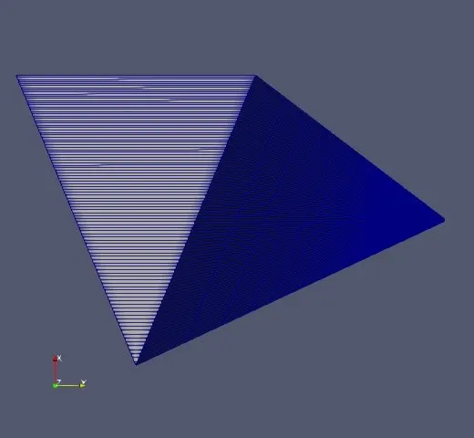
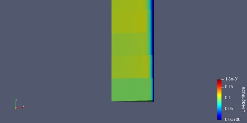
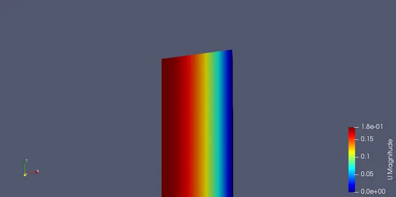
2.2.1.2 VELOCITY CONTOURS
INLET
MID_POINT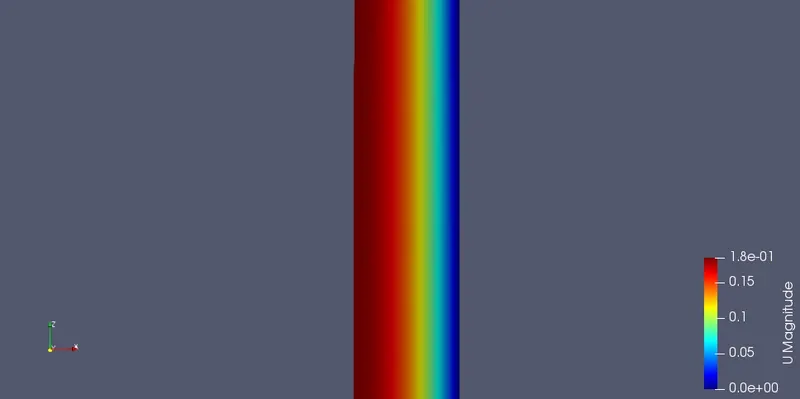
OUTLET
2.2.2 For`25^circ`
2.2.2.1 MESH
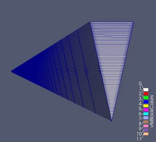
2.2.2.2 VELOCITY CONTOURS
INLET
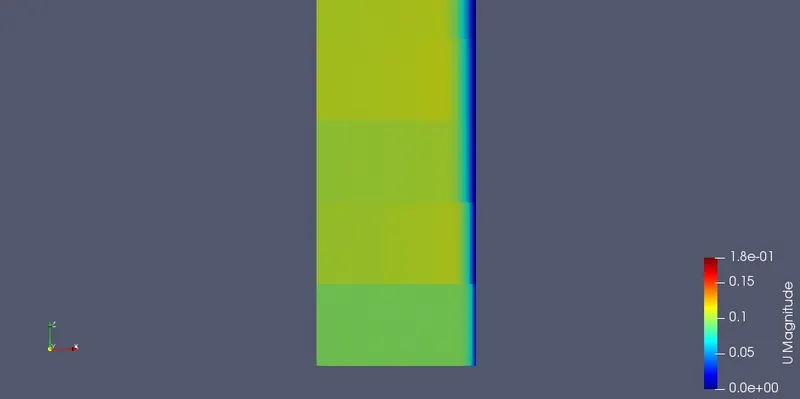
MID-POINT
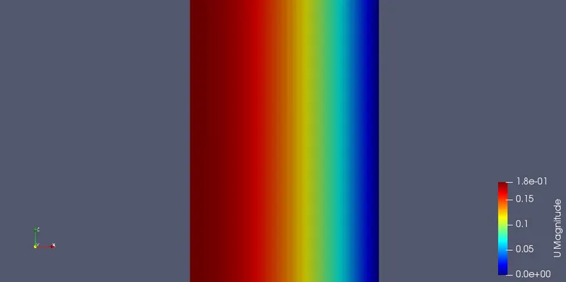
OUTLET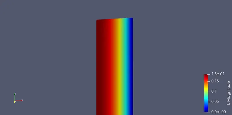
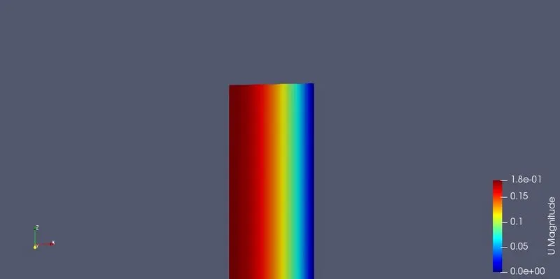
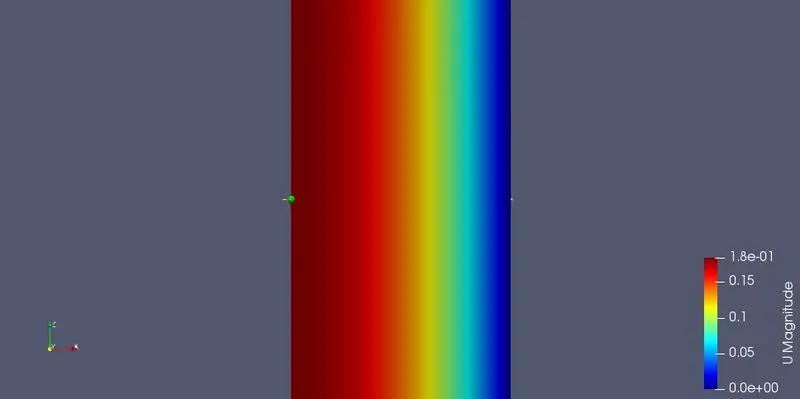
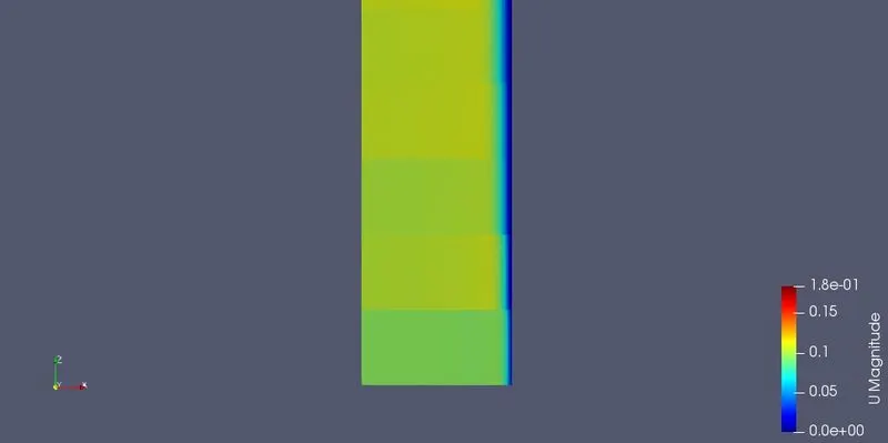
2.2.3 For`10^circ`
2.2.3.1 MESH
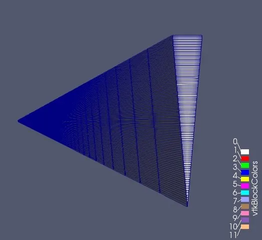
2.2.3.2 VELOCITY CONTOURS
INLET
MID-POINT
OUTLET
2.3 VELOCITY & SHEAR STRESS PROFILES AT DIFFERENT SECTIONS
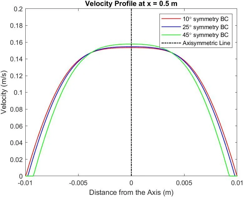
2.3.1 Velocity Profiles
At x = 0.5 (Start of Flow/Under-developed flow)
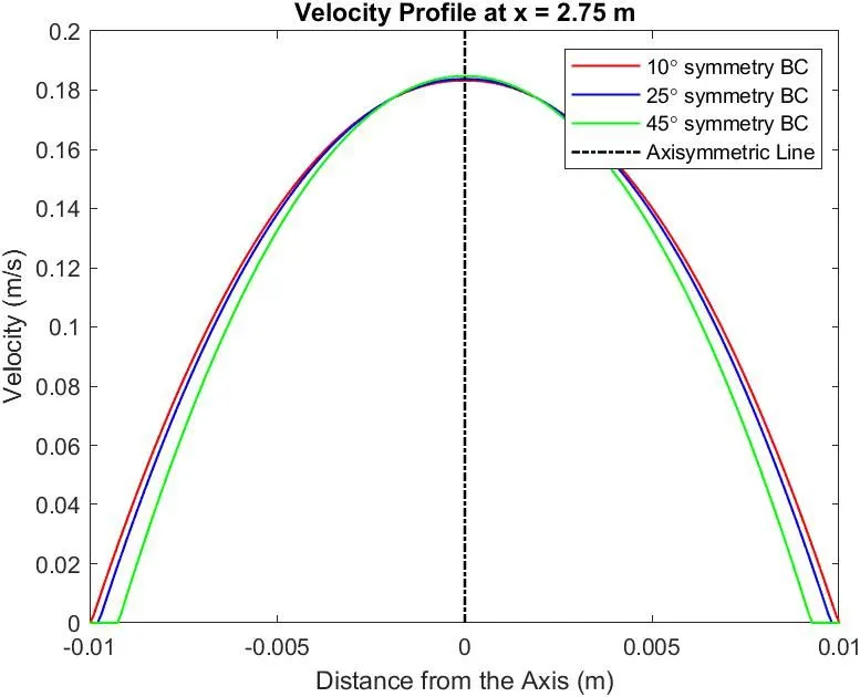
At x = 2.75 (Fully-developed flow)
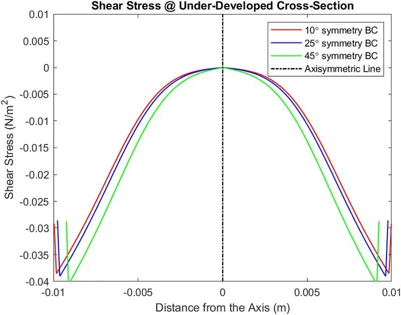
2.3.2 Shear Stress (Tau) Profiles
At x = 0.5 (Under-developed flow)
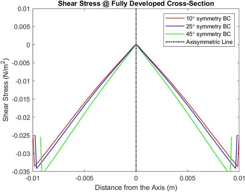
At x = 2.75 (Fully-developed flow)
1.4 COMPARISON
|
Comparison between Wedge and Symmetry Boundary types with Analytical Results |
||||
|
Boundary Type |
Angle |
Maximum Velocity (Analytical) |
Maximum Velocity using icoFoam solver |
Error % |
|
Wedge |
10 |
0.1875 |
0.1835 |
2.13 |
|
25 |
0.1875 |
0.1839 |
1.92 |
|
|
45 |
0.1875 |
0.1848 |
1.44 |
|
|
Symmetry |
10 |
0.1875 |
0.1832 |
2.3 |
|
25 |
0.1875 |
0.1838 |
1.97 |
|
|
45 |
0.1875 |
0.1848 |
1.44 |
|
For both Wedge and Symmetry BCs it is seen that the accuracy improves with greater angle used to simulate. However, for smaller angles, the wedge type BC is more accurate while both have similar accuracies at higher angles.