Week 12 - Validation studies of Symmetry BC vs Wedge BC in OpenFOAM vs Analytical H.P equation
Aim : Simulate a Laminar Incompressible Newtonian flow through a pipe with different wedge angle of 10,24,45 degree and run the simulations for Symmetry Boundary Condition and Wedge Boundary Condition for all angles and validate the result with the Analytical H.P equation.
Thoery :
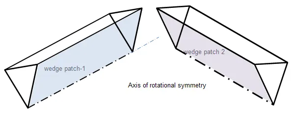
- Wedge Boundary Condition : Wedge Boundary Conditions are only used to define an axissymmetric model.The geometry and the flow must be axis-symmetric to a center line such that all the physical variables of the flow have same values distribution at a given radius for all angles of the wedge.
It works only for 2D cases.This Boundary Condition is specified by two planes,seperated by side of the domain(like front and back).The model is axis-symmetric such that at any given r=R all `thetas` and all Z-slice have same physical values.
A good example is the flow in a circular pipe where the flow and pipe axes coincide.


- Symmetry Boundary Condition :Symmetry Boundary Condition defines a mirror face/surface.It is used whent the geometry and the flow field pattern of developed solution are mirrored along that surface.By using this boundary condition the simulation time can be reduced as the geometry is halved.
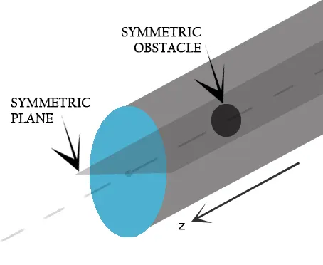
- Difference Between Wedge and Symmetry Boundary Conditions :
| Wedge Boundary Condition. | Symmetry Boundary Condtion. |
| This Boundary Conditions are used for model and geometry which are axis-symmetric to an center line or an axis. | It is used to reflect the model and flow field pattern along a face/surface. |
| All fluxes and flow field varaibles are not set to zero. | All fluxes and flow field varaibles are set to zero. |
| The values of the flow variables will be similar ar given radius at all angles. | The flow variables pattern and also the gradients at every distance are mirrored along the symmetric face . |
| The Navier-Stokes equation are applied to cylindrical coordiantes and then the transformation is done for wedge angle. | The Navier-Stokes equation are applied to the Cartesian Coordinates. |
- BlockMeshDict file code for Wedge Boundary Condition :
clear all
close all
clc

%Inputs important for mesh file
D = 0.02;              %Diameter of Pipe in m
R = D/2;               %Radius of the pipe
theta = input('Enter the wedge angle :');             %Angle of the Wedge
L = 3;                 %Total lenght of Pipe in m

%Header Context
h1 = '/*--------------------------------*- C++ -*----------------------------------*\';
h2 = '  =========                 | ';
h3 = '  \\      /  F ield         | OpenFOAM: The Open Source CFD Toolbox';
h4 = '   \\    /   O peration     | Website:  https://openfoam.org';
h5 = '    \\  /    A nd           | Version:  10';
h6 = '     \\/     M anipulation  |  ';
h7 = '\*---------------------------------------------------------------------------*/';
h8 = 'FoamFile  ';

%Dictionary Context
d1 = '{  ';
d2 = '    format      ascii; ';
d3 = '    class       dictionary;  ';
d4 = '    object      blockMeshDict;  ';
d5 = '}';
d6 = '// * * * * * * * * * * * * * * * * * * * * * * * * * * * * * * * * * * * * * // ';

%ConversionToMeters
conv = 'convertToMeters 1;';

%Initializing vertices
v0 = [0 0 0];
v1 = [0 R*cosd(theta/2) R*sind(theta/2)];
v2 = [0 R*cosd(theta/2) -R*sind(theta/2)];
v3 = [L 0 0];
v4 = [L R*cosd(theta/2) R*sind(theta/2)];
v5 = [L R*cosd(theta/2) -R*sind(theta/2)];

%Initializing arcs
arc1 = [0 R 0];
arc2 = [L R 0];

%Naming the file and writting the context
b = fopen('blockMeshDict.txt','w')

fprintf(b,'%s\n',h1);
fprintf(b,'%s\n',h2);
fprintf(b,'%s\n',h3);
fprintf(b,'%s\n',h4);
fprintf(b,'%s\n',h5);
fprintf(b,'%s\n',h6);
fprintf(b,'%s\n',h7);
fprintf(b,'%s\n',h8);

fprintf(b,'%s\n',d1);
##fprintf(b,'%s\n',d);
fprintf(b,'%s\n',d2);
fprintf(b,'%s\n',d3);
fprintf(b,'%s\n',d4);
fprintf(b,'%s\n',d5);
fprintf(b,'%s\n',d6);

fprintf(b,'\n');

fprintf(b,'%s\n',conv);

%Writing Vertices
fprintf(b,'\n');
fprintf(b,'%s\n','vertices');
fprintf(b,'%s\n','(');
fprintf(b,'\t(%f %f %f)\n',v0(1),v0(2),v0(3));
fprintf(b,'\t(%f %f %f)\n',v1(1),v1(2),v1(3));
fprintf(b,'\t(%f %f %f)\n',v2(1),v2(2),v2(3));
fprintf(b,'\t(%f %f %f)\n',v3(1),v3(2),v3(3));
fprintf(b,'\t(%f %f %f)\n',v4(1),v4(2),v4(3));
fprintf(b,'\t(%f %f %f)\n',v5(1),v5(2),v5(3));
fprintf(b,'%s\n',');');

%Writing Block
fprintf(b,'%s\n',' ');
fprintf(b,'%s\n','blocks');
fprintf(b,'%s\n','(');
fprintf(b,'\t%s\n','hex (0 2 1 0 3 5 4 3) (30 1 300) simpleGrading (1 1 1)')
fprintf(b,');\n');

%Writing Edges
fprintf(b,'%s\n',' ');
fprintf(b,'%s\n','edges');
fprintf(b,'%s\n','(');
fprintf(b,'\t arc 1 2 (%f %f %f)\n',arc1(1),arc1(2),arc1(3));
fprintf(b,'\t arc 5 4 (%f %f %f)\n',arc2(1),arc2(2),arc2(3));
fprintf(b,');\n');


%Writing Boundaries
fprintf(b,'%s\n',' ');
fprintf(b,'%s\n','boundary');
fprintf(b,'%s\n','(');

%Inlet Boundary
fprintf(b,'\t%s\n','Inlet');
fprintf(b,'\t%s\n','{');
fprintf(b,'\t\t%s\n','type patch;');
fprintf(b,'\t\t%s\n','faces');
fprintf(b,'\t\t%s\n','(');
fprintf(b,'\t\t\t%s\n','(0 1 2 0)');
fprintf(b,'\t\t%s\n',');');
fprintf(b,'\t%s\n','}');

%Outlet Wall
fprintf(b,'\t%s\n','Outlet');
fprintf(b,'\t%s\n','{');
fprintf(b,'\t\t%s\n','type patch;');
fprintf(b,'\t\t%s\n','faces');
fprintf(b,'\t\t%s\n','(');
fprintf(b,'\t\t\t%s\n','(3 5 4 3)');
fprintf(b,'\t\t%s\n',');');
fprintf(b,'\t%s\n','}');

%Axis
fprintf(b,'\t%s\n','Axis');
fprintf(b,'\t%s\n','{');
fprintf(b,'\t\t%s\n','type empty;');
fprintf(b,'\t\t%s\n','faces');
fprintf(b,'\t\t%s\n','(');
fprintf(b,'\t\t\t%s\n','(3 0 0 3)');
fprintf(b,'\t\t%s\n',');');
fprintf(b,'\t%s\n','}');

%Front_Wedge
fprintf(b,'\t%s\n','Front_wedge');
fprintf(b,'\t%s\n','{');
fprintf(b,'\t\t%s\n','type wedge;');
fprintf(b,'\t\t%s\n','faces');
fprintf(b,'\t\t%s\n','(');
fprintf(b,'\t\t\t%s\n','(0 3 4 1)');
fprintf(b,'\t\t%s\n',');');
fprintf(b,'\t%s\n','}');

%Back_wedge
fprintf(b,'\t%s\n','Back_wedge');
fprintf(b,'\t%s\n','{');
fprintf(b,'\t\t%s\n','type wedge;');
fprintf(b,'\t\t%s\n','faces');
fprintf(b,'\t\t%s\n','(');
fprintf(b,'\t\t\t%s\n','(5 3 0 2)');
fprintf(b,'\t\t%s\n',');');
fprintf(b,'\t%s\n','}');

%Wall
fprintf(b,'\t%s\n','Wall');
fprintf(b,'\t%s\n','{');
fprintf(b,'\t\t%s\n','type wall;');
fprintf(b,'\t\t%s\n','faces');
fprintf(b,'\t\t%s\n','(');
fprintf(b,'\t\t\t%s\n','(1 4 5 2)');
fprintf(b,'\t\t%s\n',');');
fprintf(b,'\t%s\n','}');

fprintf(b,'%s\n',');');

%Merging Patch Pairs
fprintf(b,'%s\n',' ');
fprintf(b,'%s\n','mergePatchPairs');
fprintf(b,'%s\n','(');
fprintf(b,'%s\n',');');
fprintf(b,'\n');
fprintf(b,'// ************************************************************************* //\n');

fclose(b);- BlockMeshDict file code for Symmetry Boundary Condition :
clear all
close all
clc

%Inputs important for mesh file
D = 0.02;              %Diameter of Pipe in m
R = D/2;               %Radius of the pipe
theta = input('Enter the Wedge angle :');             %Angle of the Wedge
L = 3;                 %Total lenght of Pipe in m

%Header Context
h1 = '/*--------------------------------*- C++ -*----------------------------------*\';
h2 = '  =========                 | ';
h3 = '  \\      /  F ield         | OpenFOAM: The Open Source CFD Toolbox';
h4 = '   \\    /   O peration     | Website:  https://openfoam.org';
h5 = '    \\  /    A nd           | Version:  10';
h6 = '     \\/     M anipulation  |  ';
h7 = '\*---------------------------------------------------------------------------*/';
h8 = 'FoamFile  ';

%Dictionary Context
d1 = '{  ';
d2 = '    format      ascii; ';
d3 = '    class       dictionary;  ';
d4 = '    object      blockMeshDict;  ';
d5 = '}';
d6 = '// * * * * * * * * * * * * * * * * * * * * * * * * * * * * * * * * * * * * * // ';

%ConversionToMeters
conv = 'convertToMeters 1;';

%Initializing vertices
v0 = [0 0 0];
v1 = [0 R*cosd(theta/2) R*sind(theta/2)];
v2 = [0 R*cosd(theta/2) -R*sind(theta/2)];
v3 = [L 0 0];
v4 = [L R*cosd(theta/2) R*sind(theta/2)];
v5 = [L R*cosd(theta/2) -R*sind(theta/2)];

%Initializing arcs
arc1 = [0 R 0];
arc2 = [L R 0];

%Naming the file and writting the context
b = fopen('blockMeshDict_symmetry.txt','w')

fprintf(b,'%s\n',h1);
fprintf(b,'%s\n',h2);
fprintf(b,'%s\n',h3);
fprintf(b,'%s\n',h4);
fprintf(b,'%s\n',h5);
fprintf(b,'%s\n',h6);
fprintf(b,'%s\n',h7);
fprintf(b,'%s\n',h8);

fprintf(b,'%s\n',d1);
##fprintf(b,'%s\n',d);
fprintf(b,'%s\n',d2);
fprintf(b,'%s\n',d3);
fprintf(b,'%s\n',d4);
fprintf(b,'%s\n',d5);
fprintf(b,'%s\n',d6);

fprintf(b,'\n');

fprintf(b,'%s\n',conv);

%Writing Vertices
fprintf(b,'\n');
fprintf(b,'%s\n','vertices');
fprintf(b,'%s\n','(');
fprintf(b,'\t(%f %f %f)\n',v0(1),v0(2),v0(3));
fprintf(b,'\t(%f %f %f)\n',v1(1),v1(2),v1(3));
fprintf(b,'\t(%f %f %f)\n',v2(1),v2(2),v2(3));
fprintf(b,'\t(%f %f %f)\n',v3(1),v3(2),v3(3));
fprintf(b,'\t(%f %f %f)\n',v4(1),v4(2),v4(3));
fprintf(b,'\t(%f %f %f)\n',v5(1),v5(2),v5(3));
fprintf(b,'%s\n',');');

%Writing Block
fprintf(b,'%s\n',' ');
fprintf(b,'%s\n','blocks');
fprintf(b,'%s\n','(');
fprintf(b,'\t%s\n','hex (0 2 1 0 3 5 4 3) (30 1 300) simpleGrading (1 1 1)')
fprintf(b,');\n');

%Writing Edges
fprintf(b,'%s\n',' ');
fprintf(b,'%s\n','edges');
fprintf(b,'%s\n','(');
fprintf(b,'\t arc 1 2 (%f %f %f)\n',arc1(1),arc1(2),arc1(3));
fprintf(b,'\t arc 5 4 (%f %f %f)\n',arc2(1),arc2(2),arc2(3));
fprintf(b,');\n');


%Writing Boundaries
fprintf(b,'%s\n',' ');
fprintf(b,'%s\n','boundary');
fprintf(b,'%s\n','(');

%Inlet Boundary
fprintf(b,'\t%s\n','Inlet');
fprintf(b,'\t%s\n','{');
fprintf(b,'\t\t%s\n','type patch;');
fprintf(b,'\t\t%s\n','faces');
fprintf(b,'\t\t%s\n','(');
fprintf(b,'\t\t\t%s\n','(0 1 2 0)');
fprintf(b,'\t\t%s\n',');');
fprintf(b,'\t%s\n','}');

%Outlet Wall
fprintf(b,'\t%s\n','Outlet');
fprintf(b,'\t%s\n','{');
fprintf(b,'\t\t%s\n','type patch;');
fprintf(b,'\t\t%s\n','faces');
fprintf(b,'\t\t%s\n','(');
fprintf(b,'\t\t\t%s\n','(3 5 4 3)');
fprintf(b,'\t\t%s\n',');');
fprintf(b,'\t%s\n','}');

%Axis
fprintf(b,'\t%s\n','Axis');
fprintf(b,'\t%s\n','{');
fprintf(b,'\t\t%s\n','type empty;');
fprintf(b,'\t\t%s\n','faces');
fprintf(b,'\t\t%s\n','(');
fprintf(b,'\t\t\t%s\n','(3 0 0 3)');
fprintf(b,'\t\t%s\n',');');
fprintf(b,'\t%s\n','}');

%Front_Wedge
fprintf(b,'\t%s\n','Front');
fprintf(b,'\t%s\n','{');
fprintf(b,'\t\t%s\n','type symmetry;');
fprintf(b,'\t\t%s\n','faces');
fprintf(b,'\t\t%s\n','(');
fprintf(b,'\t\t\t%s\n','(0 3 4 1)');
fprintf(b,'\t\t%s\n',');');
fprintf(b,'\t%s\n','}');

%Back_wedge
fprintf(b,'\t%s\n','Back');
fprintf(b,'\t%s\n','{');
fprintf(b,'\t\t%s\n','type symmetry;');
fprintf(b,'\t\t%s\n','faces');
fprintf(b,'\t\t%s\n','(');
fprintf(b,'\t\t\t%s\n','(5 3 0 2)');
fprintf(b,'\t\t%s\n',');');
fprintf(b,'\t%s\n','}');

%Wall
fprintf(b,'\t%s\n','Wall');
fprintf(b,'\t%s\n','{');
fprintf(b,'\t\t%s\n','type wall;');
fprintf(b,'\t\t%s\n','faces');
fprintf(b,'\t\t%s\n','(');
fprintf(b,'\t\t\t%s\n','(1 4 5 2)');
fprintf(b,'\t\t%s\n',');');
fprintf(b,'\t%s\n','}');

fprintf(b,'%s\n',');');

%Merging Patch Pairs
fprintf(b,'%s\n',' ');
fprintf(b,'%s\n','mergePatchPairs');
fprintf(b,'%s\n','(');
fprintf(b,'%s\n',');');
fprintf(b,'\n');
fprintf(b,'// ************************************************************************* //\n');

fclose(b);
The blockMeshDict file take theta as an input for this challenge.And we have created two different blockMeshDict file for both Wedge and Symmetry Boundary Condition.
- Validating Analytical Shear and Velocity Profile with Symmetry Boundary Condition :-
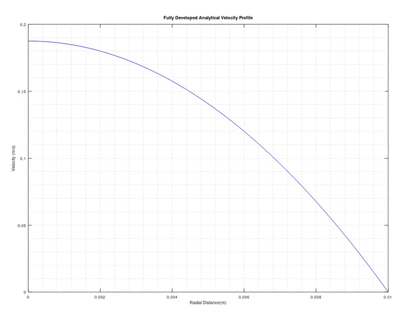
Analytical Velocity v/s Numerical Resutls in Fully Developed Region.
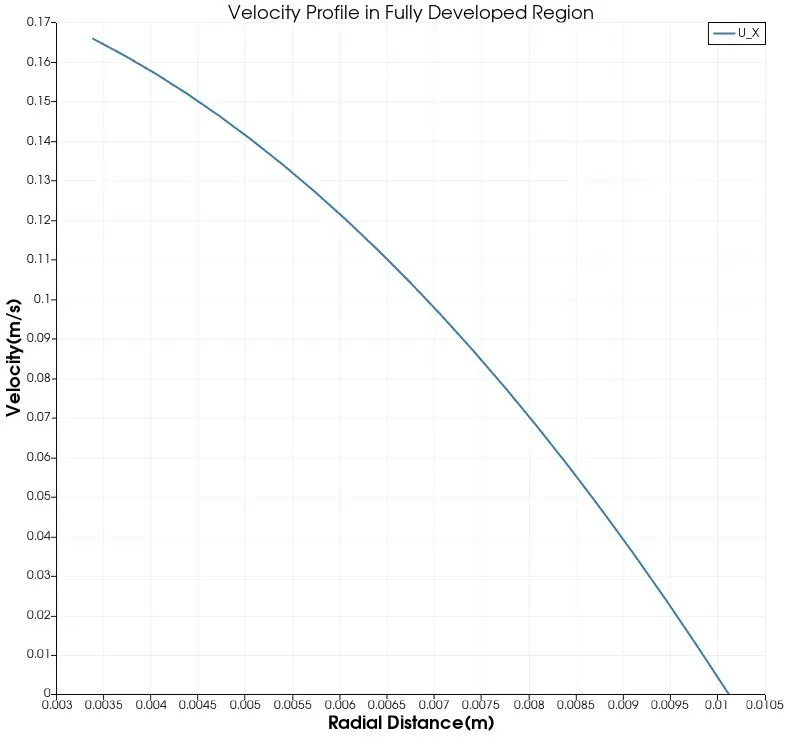 10degree profile.
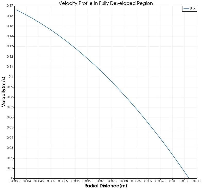 25degree
 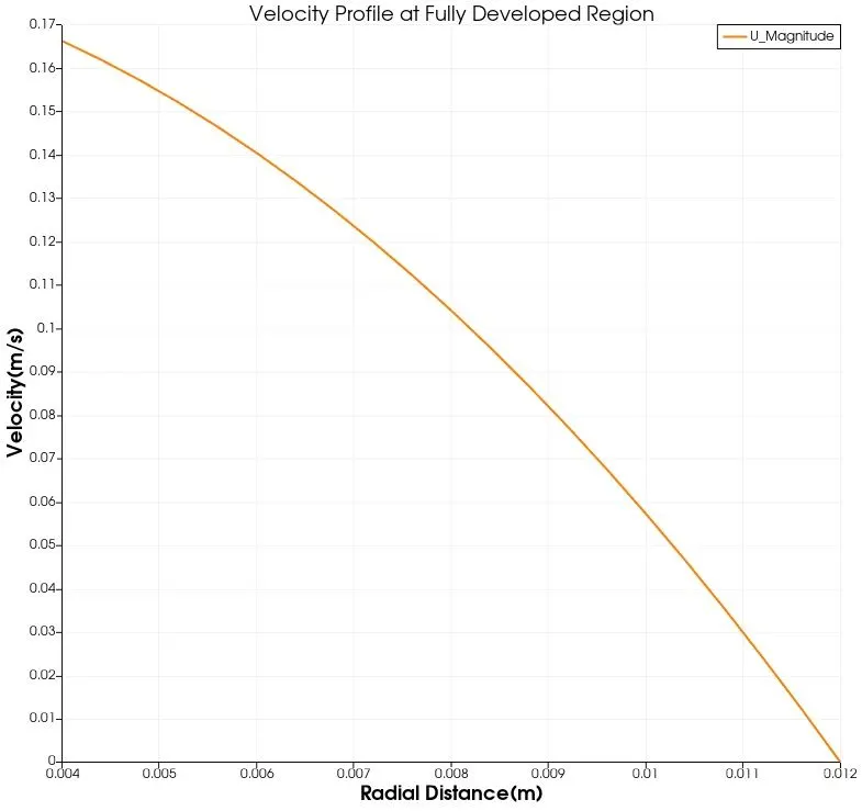 45 degree.
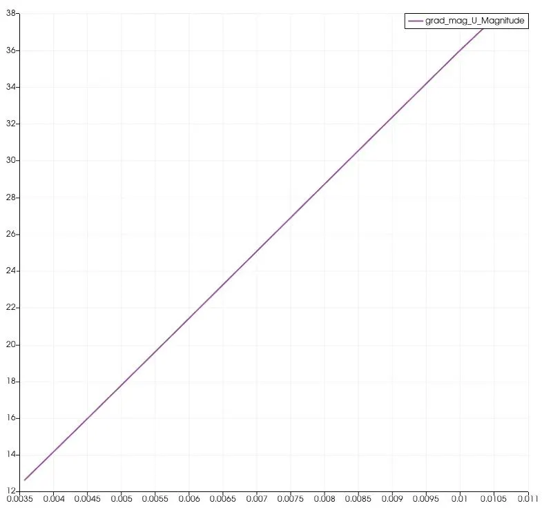
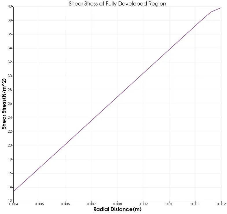
Analytical Shear Stress v/s Numerical Resutls in Fully Developed Region.
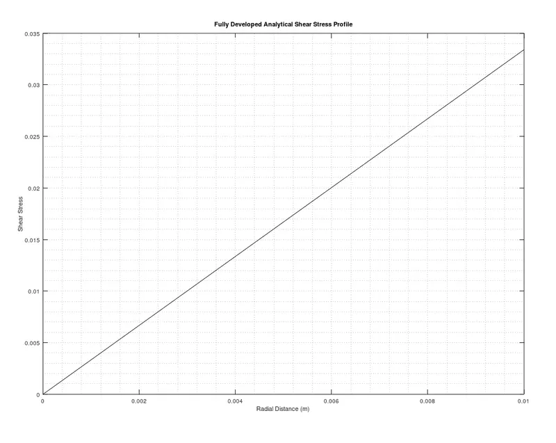
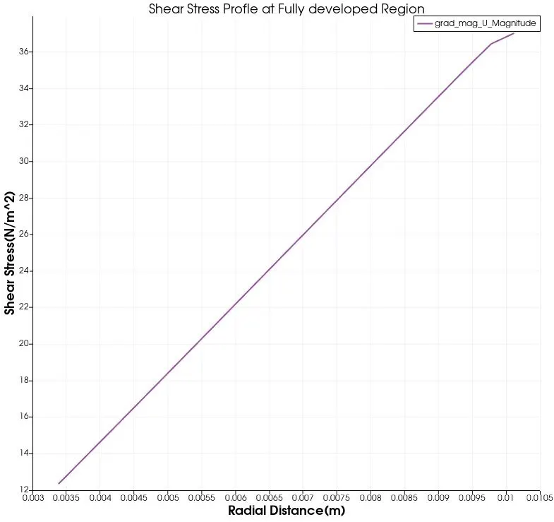 10 degree
 25degree
  45degree
- Validating Analytical Shear and Velocity Profile with Wedge Boundary Condition :-
Analytical Velocity v/s Numerical Resutls in Fully Developed Region.
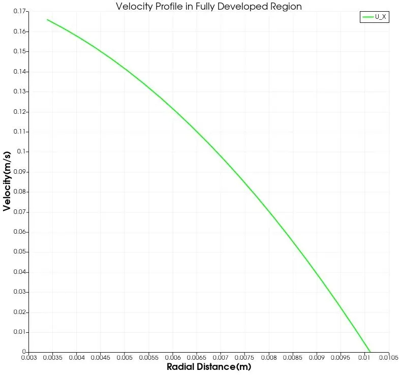 10 degree
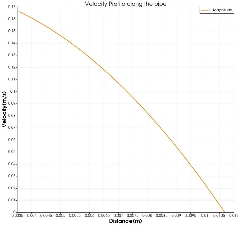 25 degree
 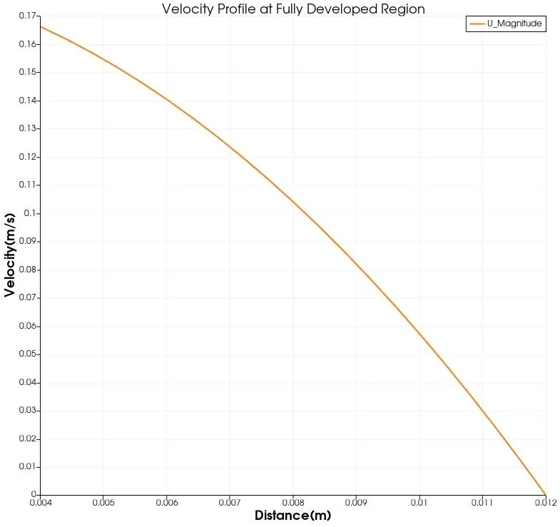 45 degree
Analytical Shear Stress v/s Numerical Resutls in Fully Developed Region.
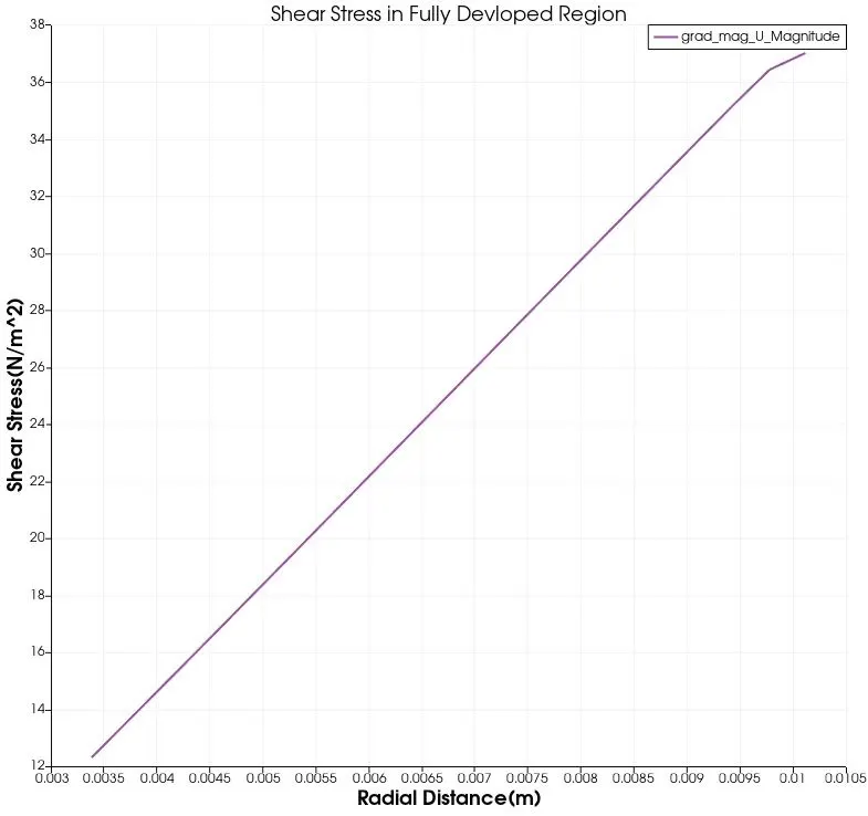 10 degree
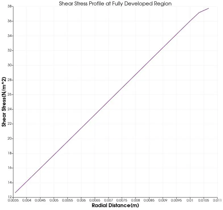 25 degree
 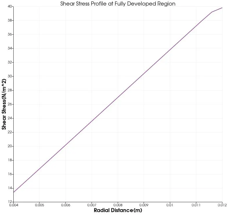 45 degree.
- Observation for Velocity Profile for Symmetry and Wedge Boundary Condition.
From the above plots shown we can say from that the Analytical Velocity profile holds good with the 10 and 25 degree wedge angle for symmetry boundary condition while the 45 degree shows a greater variation in profile especially near the wall.The same variation of velocity is been captured for the Wedge Boundary condition for 45 degree angle.As for the wedge boundary condition case we can say that 10 degree holds good with the analytical plot with 25 degrees is also holds good but the same variation can be seen in the 45 degree wedge condition as shown in the symmetry condition.Also when the angle of wedge increased we can see increase in executing time for the solution for both boundary conditions.It is best to use the suitable boundary condition related to the case and keep the wedge angle minimum or less than 5 degress.
Therefore,from the above results for the velocity profile in fully developed region we can say that,if wedge condition is used then the angle should be less than 5 degrees and for symmtry boundary condition 10 and 25 degrees are acceptable.
- Observation for Shear Stress Profile for Symmetry and Wedge Boundary Condition.
As case for the Shear stress profile for symmetry condition all angle gave the value closest to the analytical plot,but for the wedge condition the plot of 10 degree is seen to be the good condition that is closest to the analytical value.
Similar conclusion for the shear stress profile for wedfe angle 10 for wedge boundary condition is that the angle of the wedge should be less than 5 for the numerical result to be accurate.
- Code for Computing the Analytical Values :-
clear all
close all
clc

d = 0.02;
r = d/2;
re = 2100;
mu = 0.891e-3;
rho = 997.13;
v_avg = 0.09373;
v_max = 2*v_avg;
R = linspace(0,r,105);

%Validating analytical and numerical velocity profile and shear stress profile
%at fully developed region

for i = 1:length(R)
  u(i) = 2*v_avg*(1-(R(i)^2/r^2));
  tau(i) = 2*mu*v_max*(abs(R(i)))/r^2;
end


plot(R,u,'b');
xlabel('Radial Distance(m)');
ylabel('Velocity (m/s)');
title('Fully Developed Analytical Velocity Profile');
grid minor;

plot(R,tau,'k');
xlabel('Radial Distance (m)');
ylabel('Shear Stress');
title('Fully Developed Analytical Shear Stress Profile');
grid minor;
Conclusion :-The Wedge boundary condition is the best to use for the axis-symmetric cases this condition will produce accurate results if the wedge angle of the model kept less than 5(`le5`).The symmetric boundary condition can mirror the flow pattern but the fluxes are set to zero.The symmetric boundary condition has given good numerical results upto 25 degrees of wedge angle but for 45 degree the results does not hold good with analytical solution.