Week 3 Challenge : CFD meshing on Turbocharger
Aim : for the given model of turbo charger perform CFD Volumetric mesh for the required volumes for given mesh lenghts for different parts.
the access to the complete model is here as it was not uploading in the file section please access it from here:
https://drive.google.com/file/d/1eUlJmpAJeToBrr78BP_cdOTLtwZ0fScP/view?usp=sharings
Requirements : turbochargerr model, mesh lenghts for different parts as mentioned :
- Blade stage-1 = 1 mm
- Blade stage-2 = 1 mm
- Impeller = 2 mm
- Shaft rotor = 1 mm
- Turbo casing = 5 mm
- Compressor casing = 5 mm
- Inlet casing cover = 5 mm
Procedure : 1. download the turbocharger model from the given link.
2. the model will have some overlappings and errors that we have to solve and clean the geometry.
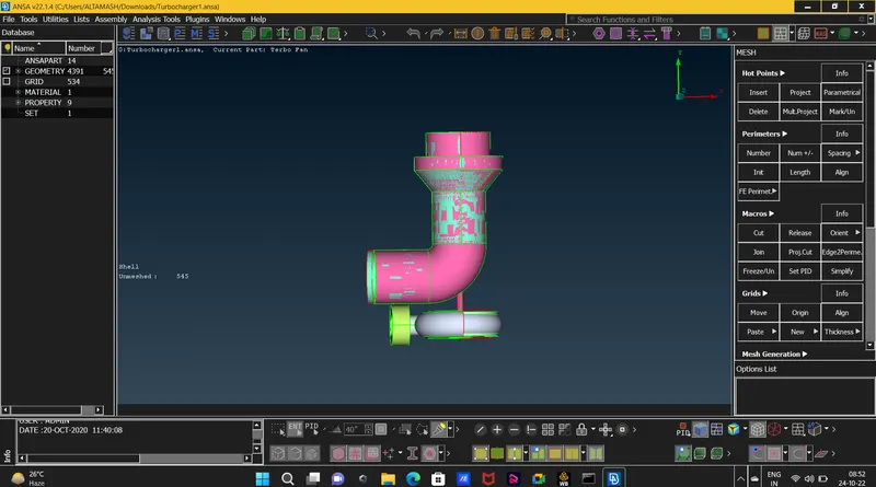
3.we will clean the overlapping surfaces by deleting the surface by selecting its hatch present on the surface deleting the extra surfaces and complete the single cons error by fill hole option as shown.
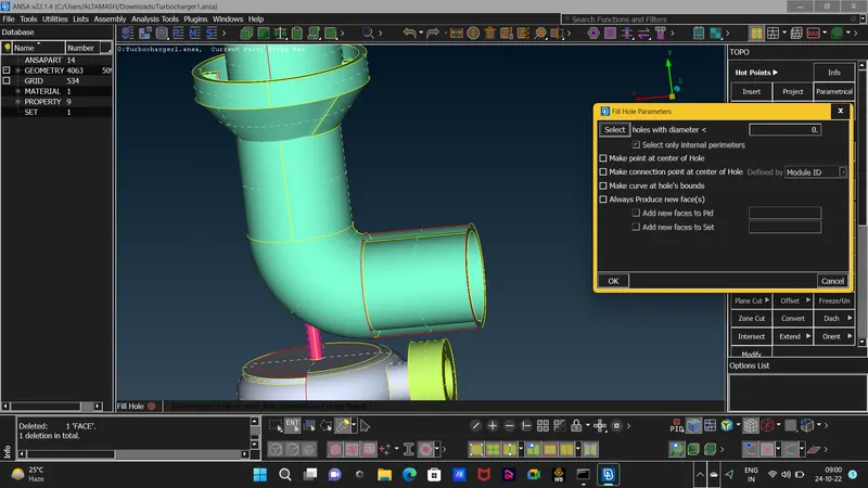
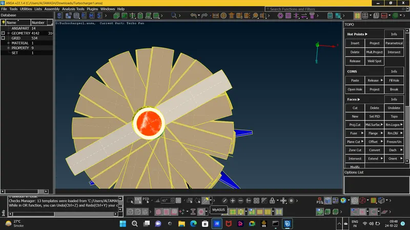
4. on some surfaces the COONS option wont work properly so we have to do some indirect work by projecting the hot points and project new surfaces for small parts first and then complete the single errors after that.
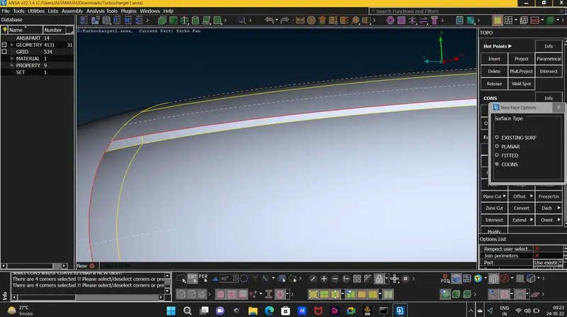
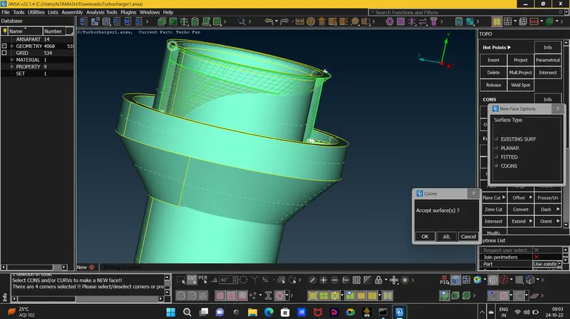
5.after the completion of creating the surface we found some penetrated surface in the interior of the model that if not solved we would get penetration error while volume mesh to delete the penetrated surface we wil use INTERSECT option to intersect the penetrated surface
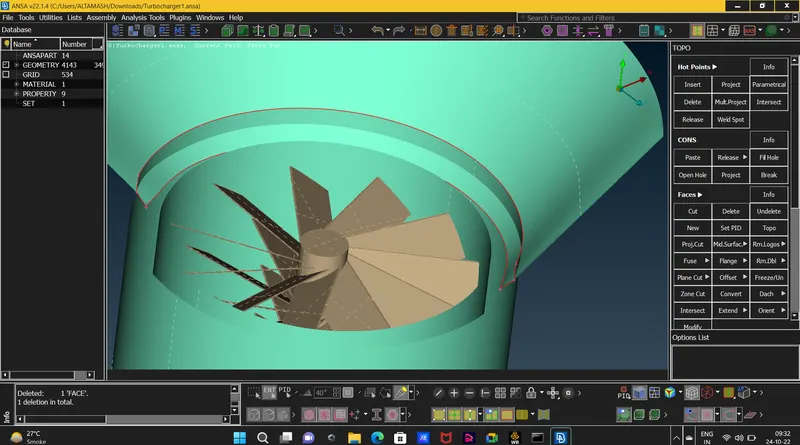
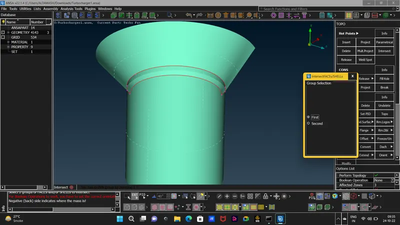
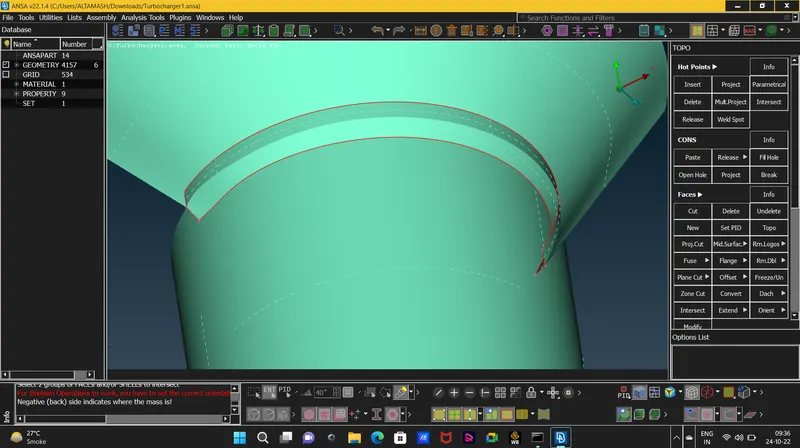 the intersected surface will show double cons as it were not showing in the first snap.
6. as we checked for errors we found a single con in interior which didnt had any neighbouring surface as shown in the snap below
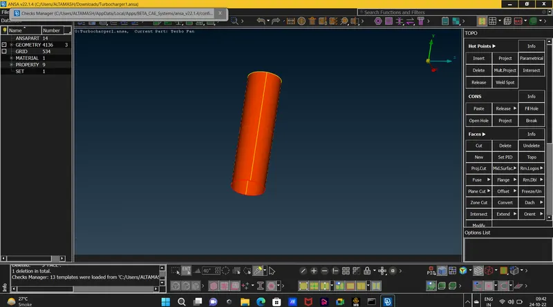 we will use topo function so it will join two single cons in one double con and the single con error will get delete.
7. there were some triple cons present in the blade parts which had only two surfaces joining so we will delete the two surfaces and make the blade and shaft surface a single volume for the simplicity of the volumetric mesh
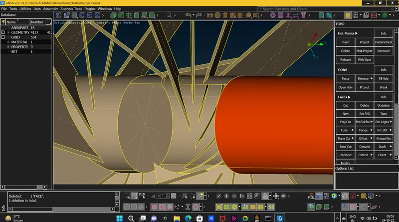
8. in the below pic,
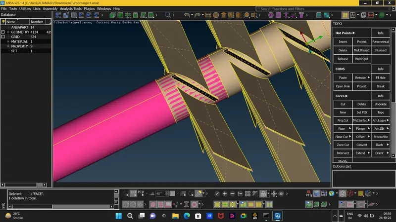 we encountered another glitching of surfaces in which the pink surface was overlapping from one end and covering the blade stage 2 part so to sole this error we projected cons and deleted the overlaped pink surface.
9. after completing the topo clean up we will close up the geometry for the surface and volumetric mesh.
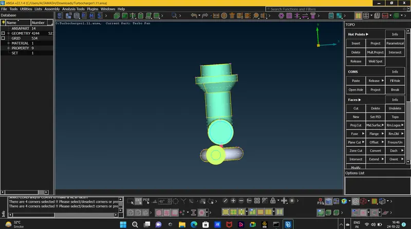
10. now we will start to create and assign PID's for new surfaces and also change the names of exsisting PID's with respect to the pid mention in the requirement.
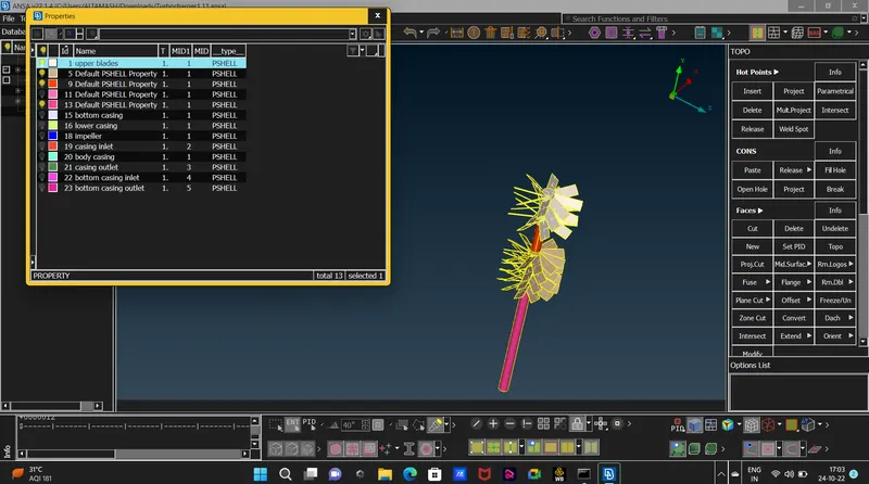
11. now we will start doing do the surface mesh , Surface mesh is pre-requisite for doing Volumetric mesh and we will mesh every part individually with the help of PID's so that we can assign different mesh lenght to each part so that the meshing will meet its requirement and also we can confirm that our meshing is completed properly by chechking in the right side of the screen where the model is present if there are 0 unmeshed surfaces so we an confirm that our meshing is done perfectly.
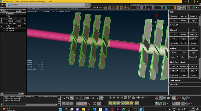
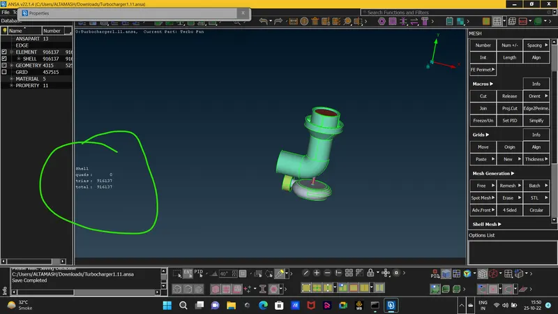
12.
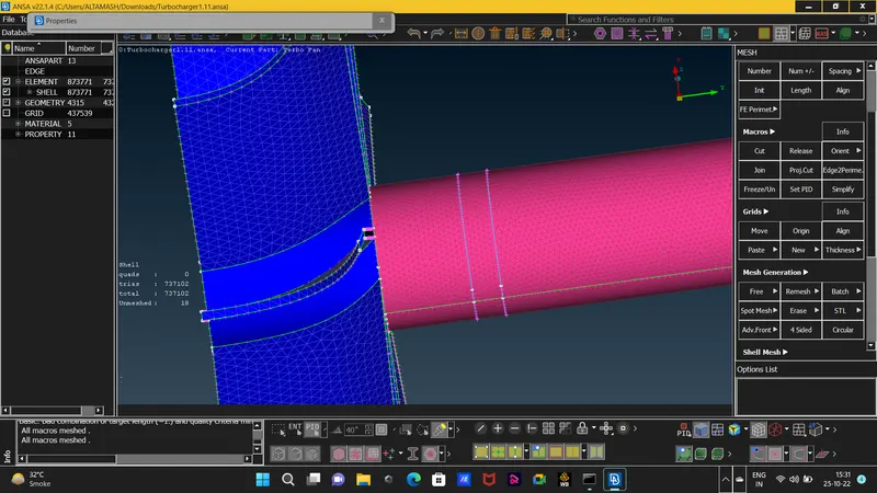
from this snap we saw that from some surfaces our mesh was getting disables , the reason for that is after meshing one surfaces selecting different surface the common surface was also selecting and there was a transition phase with respect to the sanp mention above the transition phase was from 2-1 mesh lenght so to solve this problem we only mentioned perimeter for one surface and let the macros vary fro, certain mesh lenght (2-5) that solved the problem.
also we saw some transition phase of mesh lenght where there were two mesh lenghts viewing on one single surface.
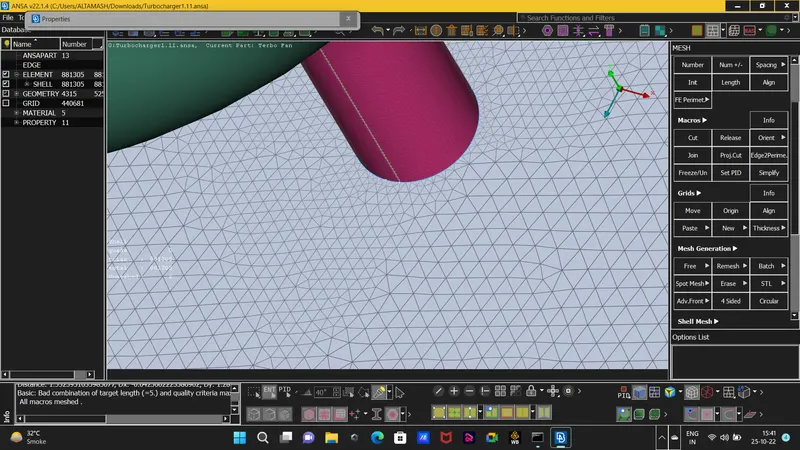 this snap is showing the transition phase.
13.now as we have completed the surface mesh we can start with volumteric mesh. click on the volumetric mesh deck then we will start doing Define funtion which will define the whole database and then it will create different volumes.

14. now we will start deleting the volumes those are covered by parent geometry or the volume covered by the thickness of surface and will keep those geometries from which the fluid will pass or accomodate.
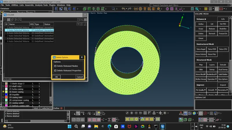
this surface is the thickness of the part and the fluid will not accomodate in here so this part is of no use in volumteric mesh.
15. after deleting the volumes that are covering the thickness of the geomtery then our model with only void volumes will look like this. 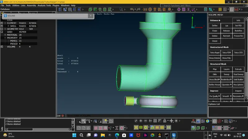
16. now we will start doing the volume mesh of only these volumes as seen in the abovr snap , and we will do cfd mesh with TETRA elements which are the 3-d elements .
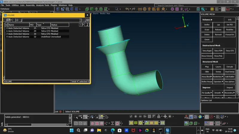
as we go on doing the mesh the status was getting update in pop up box mentioned in the snap.
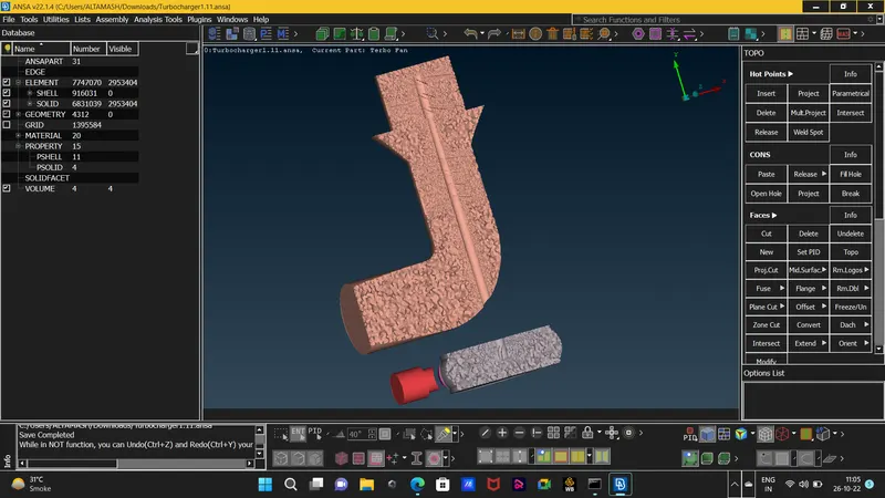
17. here is the final result of the model after doing cfd tetra mesh which is shown in the TOPO DECK under volume mode.
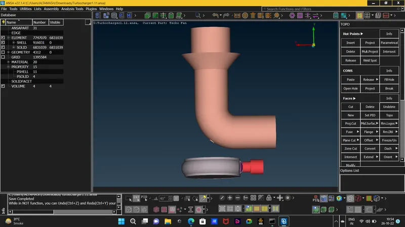
Learning Outcome : in this challange we come across different function use like RELEASE,TOPO,PROJECT cons and INTERSECT functions and also learned about different approach to solve some difficult single con errors. also we learned that for volumetric mesh, surface mesh is a pre-requisite and also that we have to do volumetric mesh for only of those volumes in which the flow will accomodate also that the surface mesh should be complete without any unmeshed surface and also if possible then create some surface a single volume that latter will help in volume meshing . the elements used in volume mesh are called tetra elements unlike the tria elements used in surface mesh, and also the volume mesh will also help us to find the fluid behavior inside the volume.
Result : the CFD meshing of Turbocharger is done and this is the final result.
 .
.