Week 4 Challenge : CFD Meshing for BMW car
Aim : for given model of BMW car perform mesh of the car with appropriate mesh lenght and quality criteria and also assign PID's to the surfaces and also create a Wind Tunnel around the car and perform volumteric CFD mesh around the car and the wind tunnel volume.
Link for the complete model is uploaded here as the size of the file is very high and it is exceeding the limit of the browse option in the challenge option in case if the is unable to upload over here
https://drive.google.com/file/d/10YsH3llqiMoi0q7q110DoojA4y0lNETp/view?usp=share_link
Requirments : target lenght and pid names for required surfaces;
- Body - 3 mm
- Lights - 4 mm
- Grills - 1 mm
- Rims and Tyres - 2 mm
- Optical Rear view mirror - 2 mm
- Window - 2 mm
- Silencer - 3 mm
- Logo - 1 mm
surface mesh elements = TRIA elements .
measurements required to create wind tunnel :
the extreme lenght of the car (x)= 1306 mm
a. the bottom wall will ne closer to the car = 75m.
b. the front wall of wind tunnel will be 4(x) from front of the car = 5878m
c. the rear wall will be 6(x) from rear of the car= 8447m.
d the upper wall will 3(x) from the upper of the car = 4292m.
e. the right and left wall are measured (x) distance from the side of the car = 1306m.
Procedure : 1. download the model from the provided link.
2. the car model as downloaded .
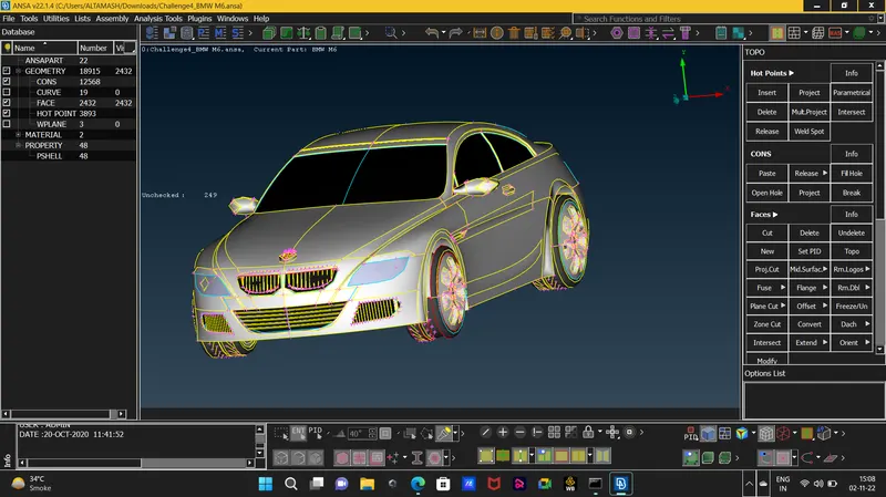
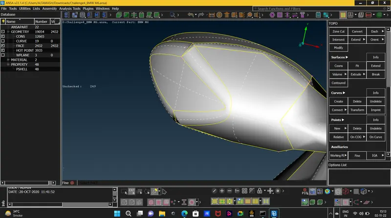
3. the geometry of the model was not fine and the geomtric shape was not defined so to make the goemtric shape fine we can use two methods
3(a). we can use the fine method in Auxilaries but this method is time consuming as it requires to click on the surface continously.
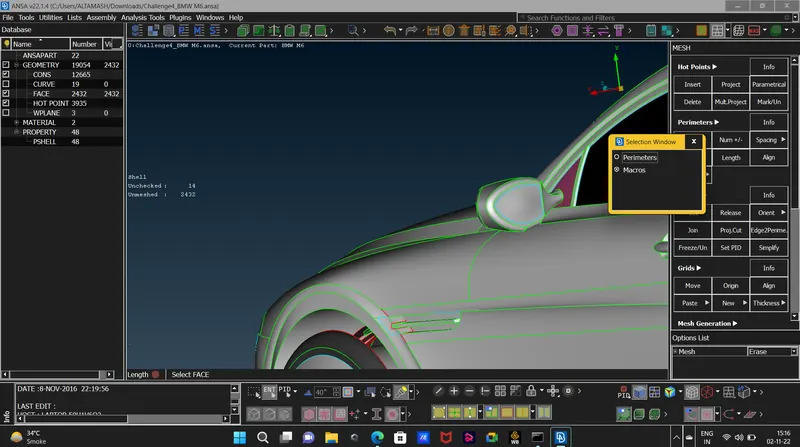
3(b). and the another method is to define lenght on the model and give perimetre and macros as 1mm lenght so it will make the whole geometry fine in effective way.
4. after making the geometry fine we will delete the half portion of the car and will only work on the other half as the car geometry is same on both side so we can copy the clean geometry part on the other side latter.
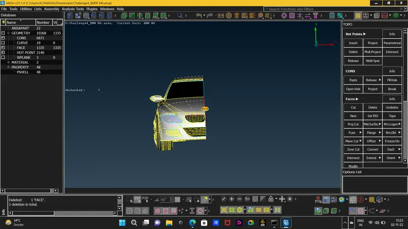
5. now we will go for the geometry clean up of the half surface , our main concern is te outside part of the car so our main aim is to make the car a single volume from inside ans as clean as possible so it will be easy at the latter stage where there will be only 7 volumes of no use that will be 4 volumes of the tyres , 2 of the silencer and 1 volume of the car inside also look for the triple surfaces.
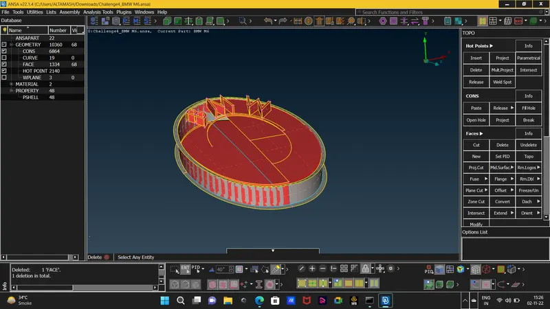
6. we will delete all the triple cons as they indicate the 3 surfaces joining which can create different volumes and also we will solve all the single cons as we dont want any open surfaces as well .
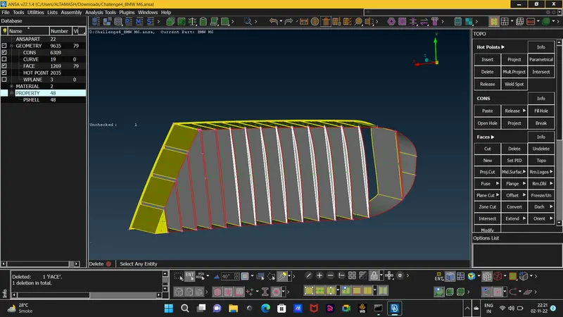
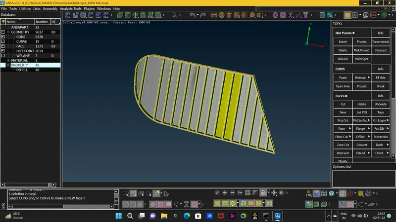 closing each surface from inside so the car will make a single volume .
7. working on the grills so to delete the single cons and while deleting triple cons we might delete some surface and we have to create it with NEW option.
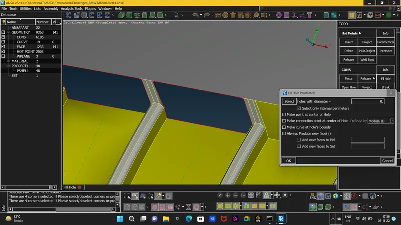
8. after cleaning the geometry do check any further errors by using Geometry function in the Checks Manager or you can also check for the single and triple cons by closing the double cons and cross hatch option in the visibility tools .
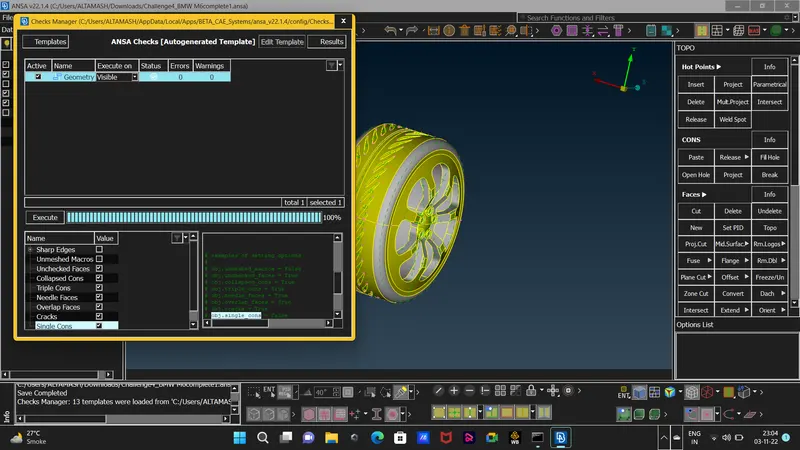
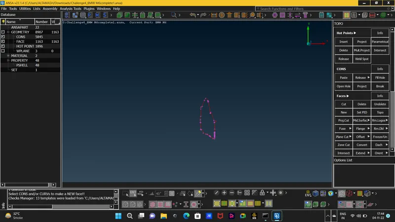
9. we also have to do some extra work on the base of the car ass there are no good surfaces and which are not good for the meshing stage.
10. after cleaning all the single and triple cons check for any further errors in the checks if there are only single cons error in the middle of the car section then we can allow that because in latter stage that single con error will get solved as we will copy the other half of the car.
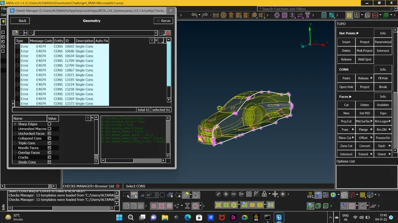
11. as we are done with the geometry clean up we will go ahead with creating and assigning new pid's as mentioned in the requirements.
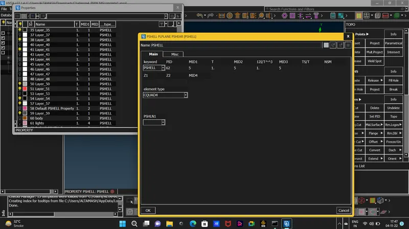
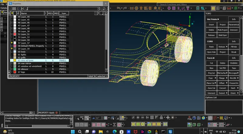
12. as we are done with the pid's we will go ahead and check the surface for any small surfaces and also delete unnecessary cuts that will make the quality criteria fail and also we will select only few quality criteria for whole car model . in this challenge we will first give the quality criteria then mesh lenght and then we will give lenght requirements for each pid's individually.
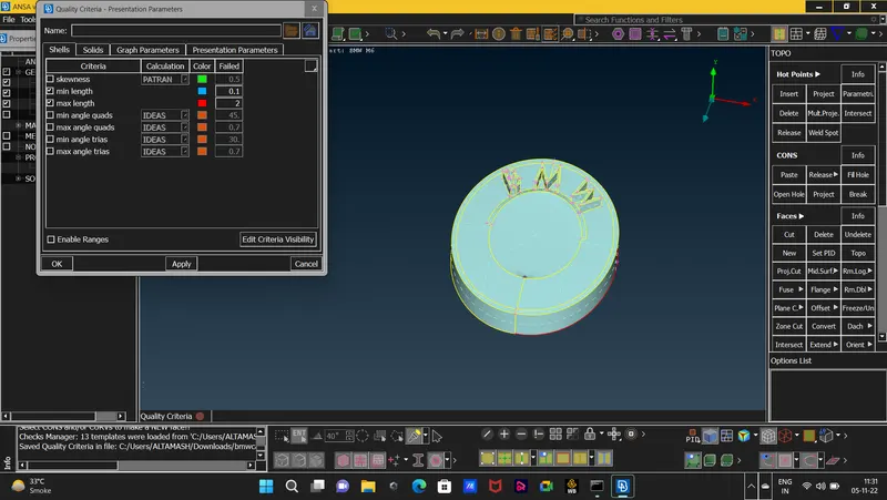 as shown in the picture we selected skewness,min and max lenght and angles which are the rest four criteria that our surface has to pass for good quality mesh.
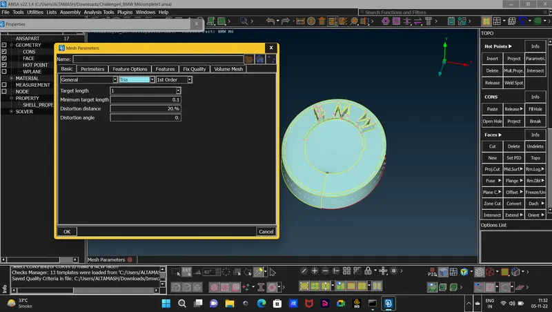
13. we will also use the Hidden mode in this challenge as in this mode we will be able to see some Off elements. these are not errors they are just some elements that failed the quality criteria and we can solve these elemnts by reconstructing them.
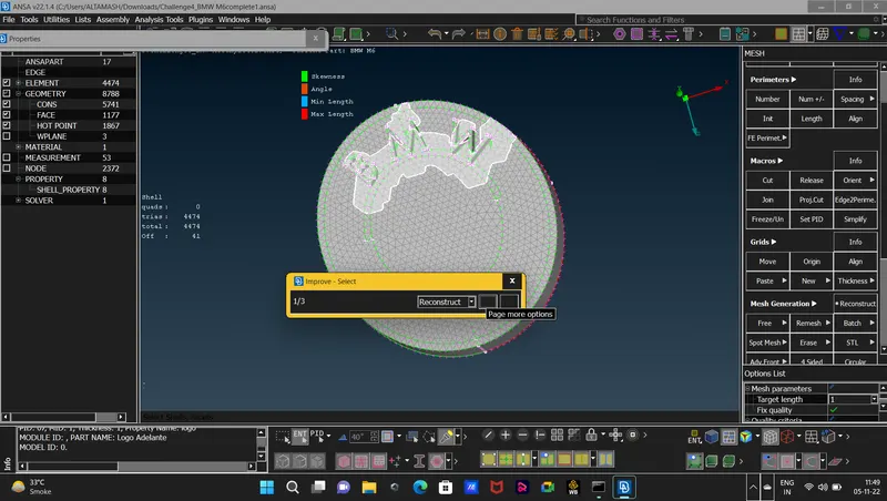
14. we solve each surface till are no single off elements that are shown on the left side of the screen beside the model.
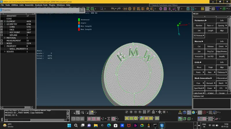
15. after completing the surface mesh of the car now its time for us to copy the clean and meshed part of the car on other side. this will be done by using Transform option in that option we willl use only copy option if we used move it will just copy the half part to the other side. then after clicking copy we will select Symmetry option and will use the 3 mirror point method
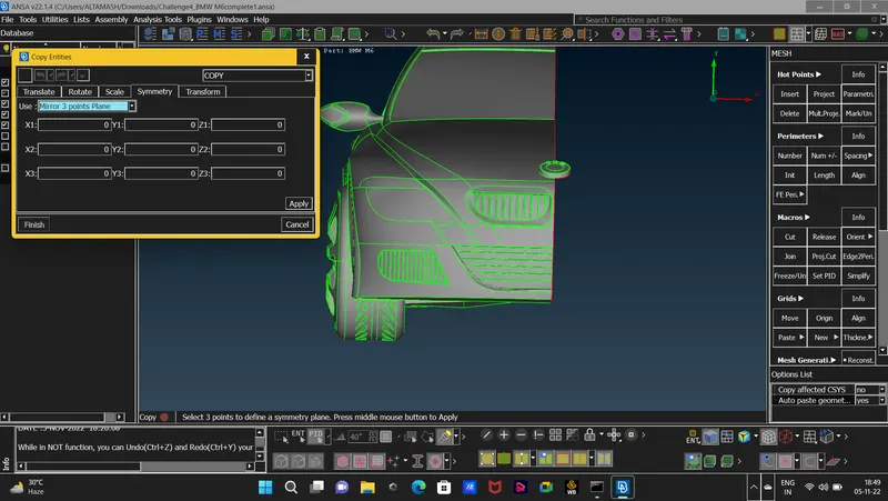 then we will select three points on the surface so that the other part will get copied by using those 3 points.
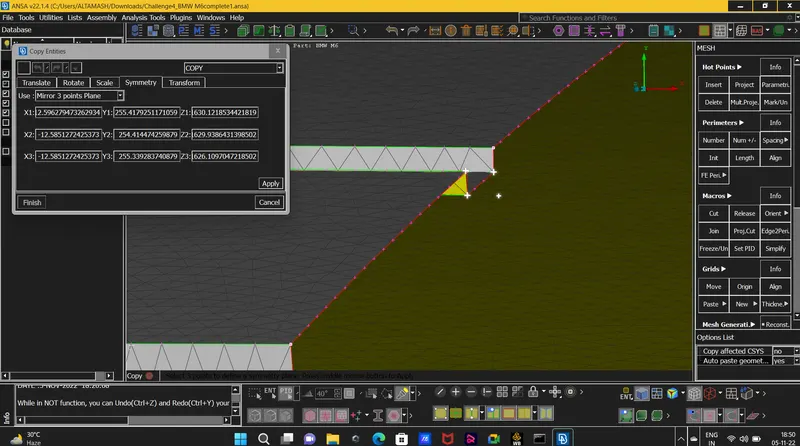 and after that we will get our half part of the car copied to the other side then we will just patch up the surface if there are any two single cons not joined properly.
16. now its time to create the Wind Tunnel. to create the wind tunnel we need some measurements to take
1. we need the extreme lenght of the model (x)= 1306mm
2. we will create the the bottom wall of the wind tunnel close to the car as our main concern will be the upper part.
3. the front wall of the wind tunnel will be 4x(x)
4. the rear wall will be 6x(x)
5. the upper wall will be 3x(x)
6. and the side walls will be (x) times of the model.
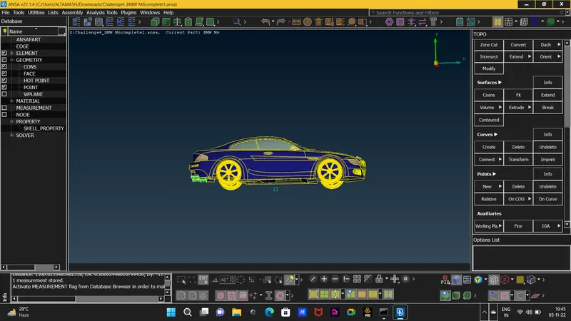
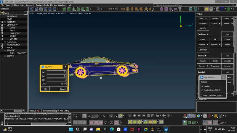
17. first we will create points by using the Points function in the Relative deck first we will give the point at the bottom of the car that will be very close to the car we will give lenght of 75m.
18. in the points function we have to define the direction in dx,dy and dz direction by inputting 1 or -1 value for positive or negative direction respectively as shown in the below figure.
 after we create the points as mentioned in point 16 we will hae points in front,rear, upper, below and to sides of the car these points will be used to create the wind tunnel surfaces.
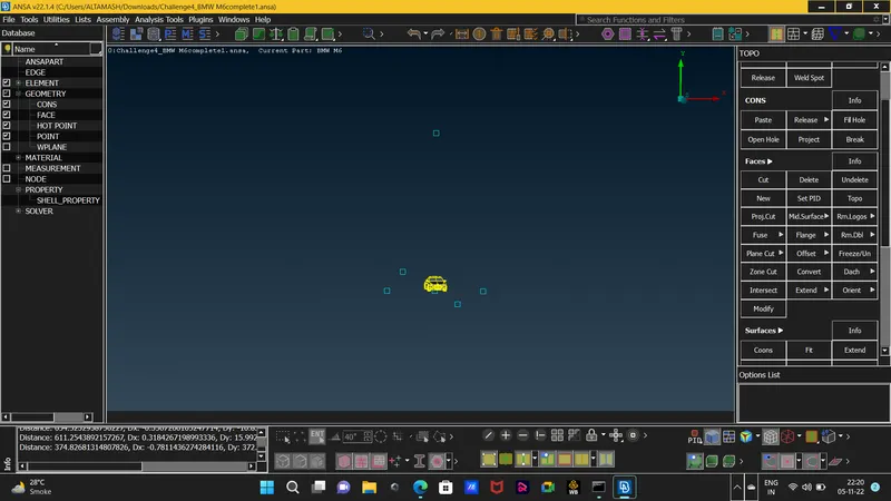 we have all the other points taking the bottom Point as the refrence for the other points.
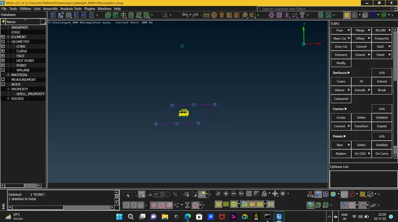
19.now we will create the face or wall of the wind tunnel by connecting the points with the help of Curve create option and then we will create a surface with NEW option as well ansa will show the pid manager to create pid for the the newly created surface .
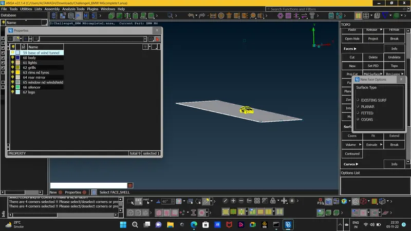
20. now we will offset the base wall or surface to the upper part by using the OFFSET function and givivng the value same as the value given to create the point above the car.
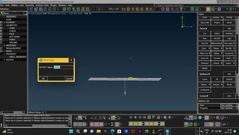 we have to mention the negative sign as the arrow is indicating to the downside of the car.
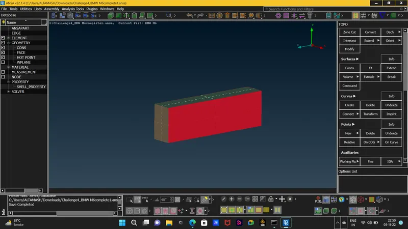
21. and after the offseting the base wall will create faces and delete the curves and the points and also will assign pid's for all the walls of the wind tunnel and the wind tummel will look like this.
22.now we will do the meshing the of the wind tunnel we will give different values of lenght to the upper and lower walls of the wind tunnel. keep note that our main corncern is the volume of the upper part of the wind tunnel and car so we will mesh the upper wall with a mesh lenght of 100mm and the lower wall with 20mm mesh lenght cause if we mesh the upper wall with finer mesh lenght then the cfd mesh will take a lot of time to complete.
23.now as for the front and the rear wall the mesh lenght varies from 20mm to 100mm from bottom to upper wall respectively here we will use the SPACING function which is used to do a meshing for varied mesh lenght we will use the GEOMETRIC BIASING as the geometric meshing we will be able to give two limits for meshing we will give min and limit value as 20 and 100mm respectively with the spacing factor of 1.1 so the spacing will increase in 1.1 factor from bottom surface upto the upper surface.
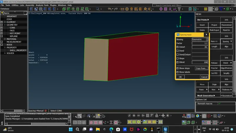 after inputting the values we will select the con for provoding direction for meshing.
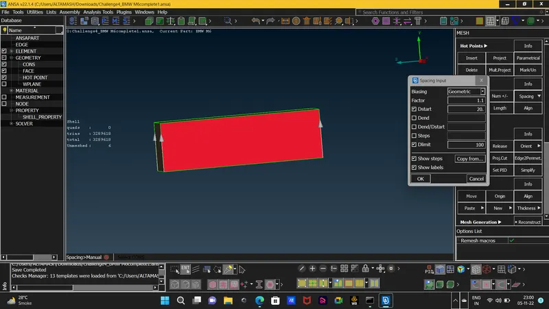 as the direction is fine we will go ahead with the meshing and will do spot mesh of the front and the rear wall seperately.
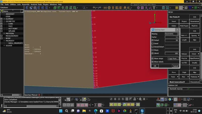 here we can see that the spacing increase from the bottom surface with the factor of 1.1 up till it reaches the given limit of 100mm on the upper wall.
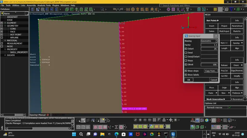
24. the mesh on the front and the reear wall will look like this.
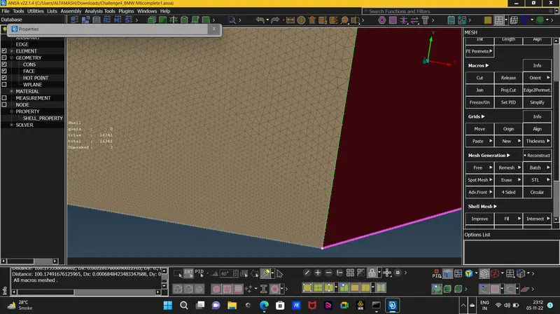
25. we will proceed to define volumes but before that we will check for any topological errors by using the check manager.
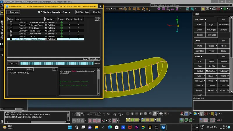
26. as there are no errors then we will proceed with Define the volumes .
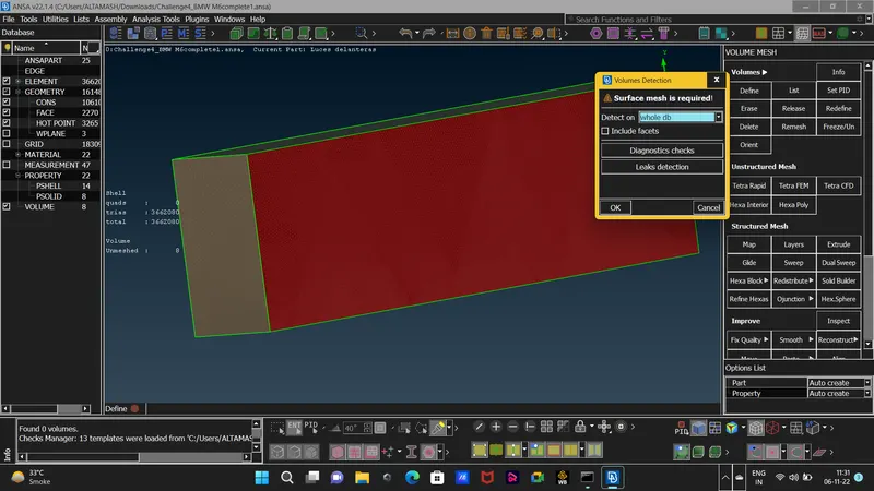 and we will recieve 8 volumes those will be:
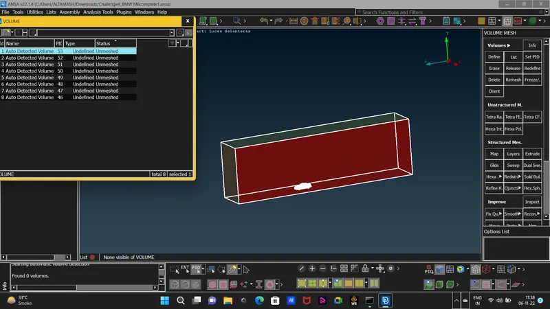 one volume between the wind tunnel and the car.
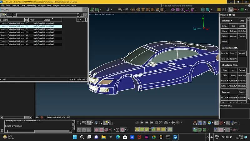 another will be the volume of the car for which we cleaned and make the interior volume as one.
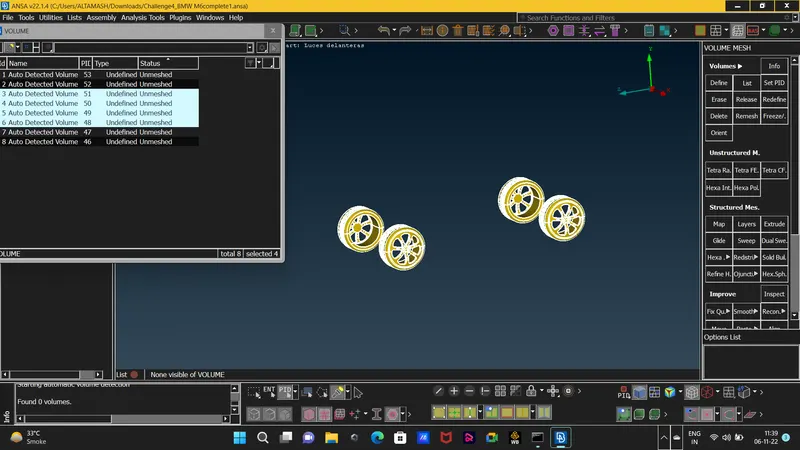 four different volumes pf each tyre and the last we will be
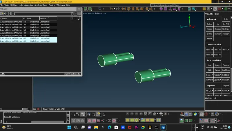 two volumes of the silencers.
27. as the volumes of the car,four tyres and both the silencers are not our concern for the cfd mesh we will delete those volumes and we will only keep the volume between the wind tunnel and the car.
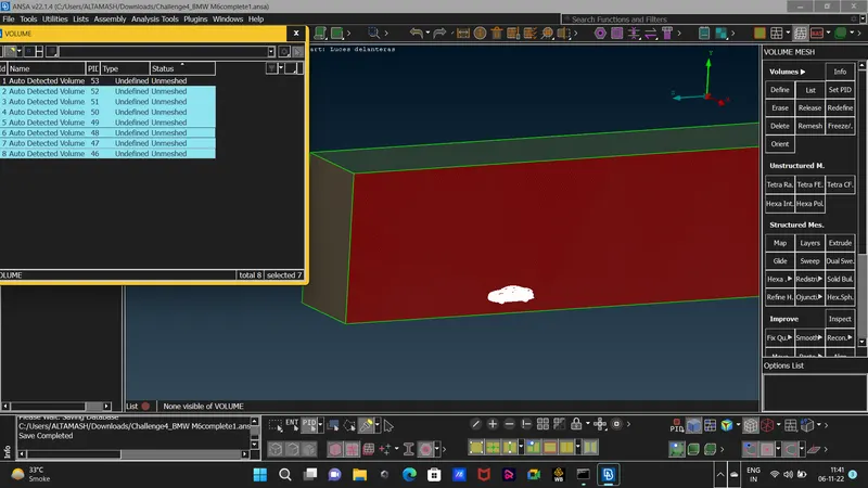 and then we will left with only one volume.
28. and now we will go ahead and proceed with the cfd tetra mesh of the volume between the wind tunnel and the car.
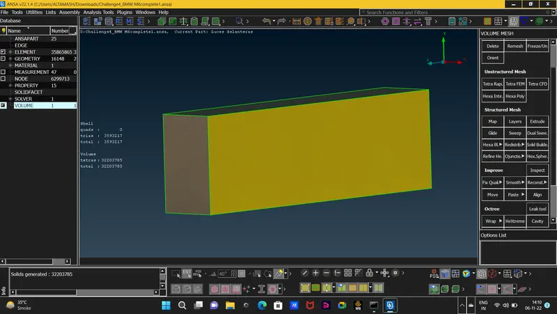 the yellow surface is the cfd tetra meshed volume between the wind tunnel and the car.
29.show the final result.
Learning Outcome : this challenge was a little challenging as we have to do more work in cleaning the geomettry and making it ready for mesh purpose we learned abot different functions which are EXTEND: which was used to extend only single cons in any selected surface, we also learned to how to make the Cons Resolution finer with the aid of Fine function as well as by using the Lenght function too.
also we learned if the model is symmetric we can delete one half and work only on the undelete part and then copy it the cleaned part by using the Transfrom function. also we learned more about the quality criteria and how to select only some quantities and also learned about the Hidden mode in which we can view the Off elements. to solve the off elements we learned the Move option in the Grids deck as well as the Smooth and Split function. we learned how we can storre our measurements, and deleteing some cuts that will make our quality criteria fail.also we encountered the same problem while meshng two joined surface with different mesh lenght and to solve that problem we deselected the cons that where sharing the meshed surface that solved the problem.
also we learned to how to create the wind tunnel and while meshing we learnedabout the Spacing function and how to use it.
Result : the CFD mesh of bmw car is complete.
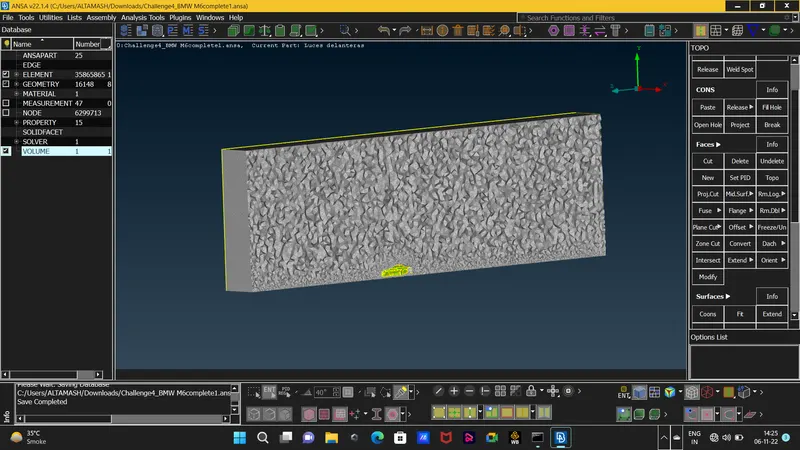
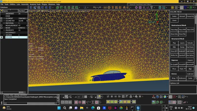 this is hiw cfd mesh looks like in wireframe mode.