Week 12 - Validation studies of Symmetry BC vs Wedge BC in OpenFOAM vs Analytical H.P equation
AIM:- The project aims to simulate the axisymmetry flow of 10`°`, 25`°`, and 45`°` for wedge and symmetry boundary conditions. After simulating, we compare both results and then we check the validation of the result by using Hagen–Poiseuille’s equation.
PROJECT DESCRIPTION:- We already discussed the whole theory in the previous challenge. So here we discuss only Hagen–Poiseuille’s equation only.
Hagen–Poiseuille’s Equation:- The Hagen–Poiseuille Equation is a fluidic law to calculate flow pressure drop in a long cylindrical pipe and it was derived separately by Poiseuille and Hagen in 1838 and 1839, respectively. So the Pressure Drop,
`∆P=P_2-P_1= (8μLV_(avg))/R^2`
= `(32μLV_(avg))/D^2`
Where `μ` is the fluid viscosity, L is the length of the pipe(> entry length), V_avg is the average velocity, R is the radius of the pipe and D is the diameter of the pipe. The Hagen–Poiseuille equation describes the relationship between pressure, fluidic resistance, and flow rate, analogous to voltage, resistance, and current, respectively, in Ohm’s law for electrical circuits (V=RI). Here, one thing we should notice is that fluid viscosity mu is proportional to the pressure drop. If mu is zero then is also zero. Therefore, the drop of pressure from `P_1`to `P_2`, in this case, is due entirely to viscous effects.
The velocity profile for fully developed laminar flow in a pipe is
`U(r) = - R^2/(4μ) ((dp)/dx)(1- r^2/R^2 )`
`= 2V_(avg)(1 – r^2/R^2 )`
Assumptions For simulation:-
- Flow is Laminar
- The working fluid is incompressible and we choose here water as working fluid.
- The viscosity of water, mu = 0.00089 kg·m−1s−1
- The density of water, `ρ = 1000 (kg)/m^3`
- The kinematic viscosity of water, `nu = mu/ ρ`
- Pipe diameter, D = 0.02
- The entry length, Lh = 0.05*Re*D
- The pipe length, L = Lh + 0.25
- Average velocity,`V_(avg) = (nu*Re)/D`
- Maximum velocity, `V_(max) = 2*V_(avg)`
- Pressure Drop, `∆P = (32μLV_avg)/D^2`
- Kinematic Pressure,`P = (∆P)/ ρ`
Because the flow is laminar and the fluid is incompressible like privious challange we choose the icoFoam solver. We divide our simulation into two parts, case-1 and case-2. Case-1 is for wedge boundary condition and case-2 is for Symmetry bondary condition. After simulation we compare both results and we check validation of the result by using Numerical analysis. For this numerical analysis we use H. P. equation.
Case-1:- Wedge Boundary Condition
First we create our Block Mesh File in MATLAB:-
clear all;
close all;
clc;

Re = 2100;          % Reynolds number
Rho = 1000;         % Density of water
mu = 0.00089;       % Dynamic viscosity of water
nu = mu/Rho;        % Kinematic viscosity of water
D = 0.02;         % Diameter of the pipe
R = D/2;            % Radius of the pipe
ent_L = 0.05*Re*D;  % Entry length
theta = 10;          % Wedge angle in degree

%Boundery condition
V_avg = (nu*Re)/D;             %Average velocity
V_max = 2*V_avg;               % Maximum velocity
L = ent_L + 0.25;              %Length of the pipe
Dell_P = (32*mu*L*V_avg)/D^2;  % Pressure drop
kin_P = Dell_P/Rho;            % Kinematic pressure drop

%Defining the points
v_0 = [0 0 0];
v_1 = [0 R*cosd(theta/2) R*sind(theta/2)];
v_2 = [0 R*cosd(theta/2) -R*sind(theta/2)];
v_3 = [L 0 0];
v_4 = [L R*cosd(theta/2) R*sind(theta/2)];
v_5 = [L R*cosd(theta/2) -R*sind(theta/2)];

%% creating a blockmeshh file
F_1 = '/*--------------------------------*- C++ -*----------------------------------*\';
F_2 = ' =========                 |';
F_3 = ' \\      /  F ield         | OpenFOAM: The Open Source CFD Toolbox';
F_4 = '  \\    /   O peration     | Website:  https://openfoam.org';
F_5 = '   \\  /    A nd           | Version:  9';
F_6 = '    \\/     M anipulation  |';
F_7 = '\*---------------------------------------------------------------------------*/';

F_8 = '// * * * * * * * * * * * * * * * * * * * * * * * * * * * * * * * * * * * * * //';

f1 = fopen('blockMeshDict3.txt','w');

fprintf(f1,"%s\n",F_1);
fprintf(f1,"%s\n",F_2);
fprintf(f1,"%s\n",F_3);
fprintf(f1,"%s\n",F_4);
fprintf(f1,"%s\n",F_5);
fprintf(f1,"%s\n",F_6);
fprintf(f1,"%s\n",F_7);

fprintf(f1,"%s\n",'FoamFile');
fprintf(f1,"%s\n",'{');
fprintf(f1, "%11s %9s\n",'version','2.0;');
fprintf(f1, "%10s %12s\n",'format','ascii;');
fprintf(f1, "%9s %18s\n",'class','dictionary;');
fprintf(f1,"%10s %20s\n",'object','blockMeshDict;');
fprintf(f1,"%s\n",'}');
fprintf(f1,"%s\n\n",F_8);
fprintf(f1,"%s\n\n",'convertToMeters 1;');

fprintf(f1,"%s\n",'vertices');
fprintf(f1,"%s\n\n",'(');
fprintf(f1,"\t(%f %f %f)\n",v_0);
fprintf(f1,"\t(%f %f %f)\n",v_1);
fprintf(f1,"\t(%f %f %f)\n",v_2);
fprintf(f1,"\t(%f %f %f)\n",v_3);
fprintf(f1,"\t(%f %f %f)\n",v_4);
fprintf(f1,"\t(%f %f %f)\n\n",v_5);

fprintf(f1,"%s\n\n",');');

fprintf(f1,"%s\n",'blocks');
fprintf(f1,"%s\n",'(');
fprintf(f1,"\t%s %s\n",'hex (0 2 1 0 3 5 4 3) (50 1 200)', 'simpleGrading (0.2 1 1)');
fprintf(f1,"%s\n\n",');');

fprintf(f1,"%s\n",'edges');
fprintf(f1,"%s\n", '(');
fprintf(f1,"\t%s (%f %f %f)\n",'arc 1 2',0,R,0);
fprintf(f1,"\t%s (%f %f %f)\n",'arc 4 5',L,R,0);
fprintf(f1, "%s\n\n",');');

fprintf(f1,"%s\n",'boundary');
fprintf(f1,"%s\n",'(');

fprintf(f1,"\t%s\n","inlet");
fprintf(f1,"\t%s\n",'{');
fprintf(f1,"\t\t%s\n",'type patch;');
fprintf(f1,"\t\t%s\n",'faces');
fprintf(f1,"\t\t%s\n",'(');
fprintf(f1,"\t\t\t(%d %d %d %d)\n",0,1,2,0);
fprintf(f1,"\t\t%s\n",');');
fprintf(f1,"\t%s\n",'}');

fprintf(f1,"\t%s\n","outlet");
fprintf(f1,"\t%s\n",'{');
fprintf(f1,"\t\t%s\n",'type patch;');
fprintf(f1,"\t\t%s\n",'faces');
fprintf(f1,"\t\t%s\n",'(');
fprintf(f1,"\t\t\t(%d %d %d %d)\n",3,4,5,3);
fprintf(f1,"\t\t%s\n",');');
fprintf(f1,"\t%s\n",'}');

fprintf(f1,"\t%s\n","front");
fprintf(f1,"\t%s\n",'{');
fprintf(f1,"\t\t%s\n",'type wedge;');
fprintf(f1,"\t\t%s\n",'faces');
fprintf(f1,"\t\t%s\n",'(');
fprintf(f1,"\t\t\t(%d %d %d %d)\n",0,3,4,1);
fprintf(f1,"\t\t%s\n",');');
fprintf(f1,"\t%s\n",'}');

fprintf(f1,"\t%s\n","back");
fprintf(f1,"\t%s\n",'{');
fprintf(f1,"\t\t%s\n",'type wedge;');
fprintf(f1,"\t\t%s\n",'faces');
fprintf(f1,"\t\t%s\n",'(');
fprintf(f1,"\t\t\t(%d %d %d %d)\n",0,2,5,3);
fprintf(f1,"\t\t%s\n",');');
fprintf(f1,"\t%s\n",'}');

fprintf(f1,"\t%s\n","pipe");
fprintf(f1,"\t%s\n",'{');
fprintf(f1,"\t\t%s\n",'type wall;');
fprintf(f1,"\t\t%s\n",'faces');
fprintf(f1,"\t\t%s\n",'(');
fprintf(f1,"\t\t\t(%d %d %d %d)\n",1,4,5,2);
fprintf(f1,"\t\t%s\n",');');
fprintf(f1,"\t%s\n",'}');

fprintf(f1,"\t%s\n","axis");
fprintf(f1,"\t%s\n",'{');
fprintf(f1,"\t\t%s\n",'type empty;');
fprintf(f1,"\t\t%s\n",'faces');
fprintf(f1,"\t\t%s\n",'(');
fprintf(f1,"\t\t\t(%d %d %d %d)\n",3,0,0,3);
fprintf(f1,"\t\t%s\n",');');
fprintf(f1,"\t%s\n",'}');

fprintf(f1,"%s\n",');');

fprintf(f1,"%s\n",'mergePatchPairs');
fprintf(f1,"%s\n",'(');
fprintf(f1,"%s\n\n",');');
fprintf(f1,"%s",F_8);
blockMeshDict file:-
/*--------------------------------*- C++ -*----------------------------------*\
 =========                 |
 \\      /  F ield         | OpenFOAM: The Open Source CFD Toolbox
  \\    /   O peration     | Website:  https://openfoam.org
   \\  /    A nd           | Version:  9
    \\/     M anipulation  |
\*---------------------------------------------------------------------------*/
FoamFile
{
    version      2.0;
    format       ascii;
    class        dictionary;
    object       blockMeshDict;
}
// * * * * * * * * * * * * * * * * * * * * * * * * * * * * * * * * * * * * * //

convertToMeters 1;

vertices
(

	(0.000000 0.000000 0.000000)
	(0.000000 0.009962 0.000872)
	(0.000000 0.009962 -0.000872)
	(2.350000 0.000000 0.000000)
	(2.350000 0.009962 0.000872)
	(2.350000 0.009962 -0.000872)

);

blocks
(
	hex (0 2 1 0 3 5 4 3) (50 1 200) simpleGrading (0.2 1 1)
);

edges
(
	arc 1 2 (0.000000 0.010000 0.000000)
	arc 4 5 (2.350000 0.010000 0.000000)
);

boundary
(
	inlet
	{
		type patch;
		faces
		(
			(0 1 2 0)
		);
	}
	outlet
	{
		type patch;
		faces
		(
			(3 4 5 3)
		);
	}
	front
	{
		type wedge;
		faces
		(
			(0 3 4 1)
		);
	}
	back
	{
		type wedge;
		faces
		(
			(0 2 5 3)
		);
	}
	pipe
	{
		type wall;
		faces
		(
			(1 4 5 2)
		);
	}
	axis
	{
		type empty;
		faces
		(
			(3 0 0 3)
		);
	}
);
mergePatchPairs
(
);

// * * * * * * * * * * * * * * * * * * * * * * * * * * * * * * * * * * * * * //
Velocity File:-
/*--------------------------------*- C++ -*----------------------------------*\
  =========                 |
  \\      /  F ield         | OpenFOAM: The Open Source CFD Toolbox
   \\    /   O peration     | Website:  https://openfoam.org
    \\  /    A nd           | Version:  9
     \\/     M anipulation  |
\*---------------------------------------------------------------------------*/
FoamFile
{
    format      ascii;
    class       volVectorField;
    object      U;
}
// * * * * * * * * * * * * * * * * * * * * * * * * * * * * * * * * * * * * * //

dimensions      [0 1 -1 0 0 0 0];

internalField   uniform (0 0 0);

boundaryField
{
    inlet
    {
        type            fixedValue;
        value           uniform (0.0934 0 0);
    }

    outlet
    {
        type            zeroGradient;
    }

    front
    {
        type            wedge;
    }
    back
    {
        type            wedge;
    }
    pipe
    {
        type            noSlip;
    }
    axis
    {
        type            empty;
    }
}

// ************************************************************************* //
Kinematic Pressure File:-
/*--------------------------------*- C++ -*----------------------------------*\
  =========                 |
  \\      /  F ield         | OpenFOAM: The Open Source CFD Toolbox
   \\    /   O peration     | Website:  https://openfoam.org
    \\  /    A nd           | Version:  9
     \\/     M anipulation  |
\*---------------------------------------------------------------------------*/
FoamFile
{
    format      ascii;
    class       volScalarField;
    object      p;
}
// * * * * * * * * * * * * * * * * * * * * * * * * * * * * * * * * * * * * * //

dimensions      [0 2 -2 0 0 0 0];

internalField   uniform 0;

boundaryField
{
    inlet
    {
        type            zeroGradient;
    }

    outlet
    {
        type            fixedValue;
        value           uniform 0.0156;
    }

    front
    {
        type            wedge;
    }
    back
    {
        type            wedge;
    }
    pipe
    {
        type            zeroGradient;
    }

    axis
    {
        type            empty;
    }
}

// ************************************************************************* //
File for Transport Properties
/*--------------------------------*- C++ -*----------------------------------*\
  =========                 |
  \\      /  F ield         | OpenFOAM: The Open Source CFD Toolbox
   \\    /   O peration     | Website:  https://openfoam.org
    \\  /    A nd           | Version:  9
     \\/     M anipulation  |
\*---------------------------------------------------------------------------*/
FoamFile
{
    format      ascii;
    class       dictionary;
    location    "constant";
    object      transportProperties;
}
// * * * * * * * * * * * * * * * * * * * * * * * * * * * * * * * * * * * * * //

nu              [0 2 -1 0 0 0 0] 8.9e-07;


// ************************************************************************* //
ControlDict File
/*--------------------------------*- C++ -*----------------------------------*\
  =========                 |
  \\      /  F ield         | OpenFOAM: The Open Source CFD Toolbox
   \\    /   O peration     | Website:  https://openfoam.org
    \\  /    A nd           | Version:  9
     \\/     M anipulation  |
\*---------------------------------------------------------------------------*/
FoamFile
{
    format      ascii;
    class       dictionary;
    location    "system";
    object      controlDict;
}
// * * * * * * * * * * * * * * * * * * * * * * * * * * * * * * * * * * * * * //

application     icoFoam;

startFrom       startTime;

startTime       0;

stopAt          endTime;

endTime         10;

deltaT          0.001;

writeControl    timeStep;

writeInterval   20;

purgeWrite      0;

writeFormat     ascii;

writePrecision  6;

writeCompression off;

timeFormat      general;

timePrecision   6;

runTimeModifiable true;


// ************************************************************************* //
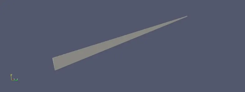
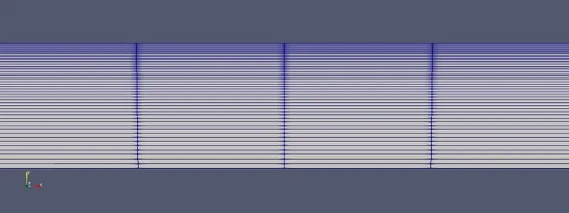
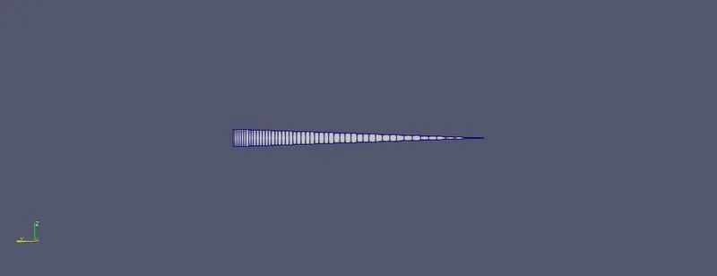
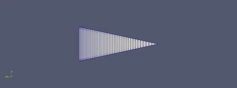
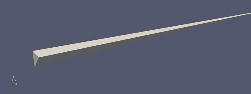
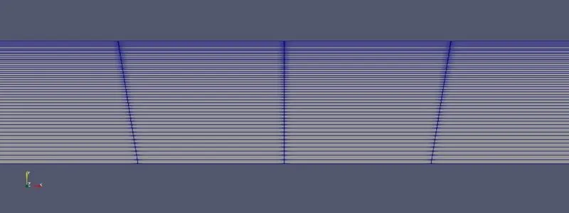
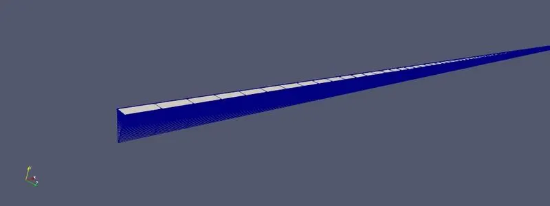
The geometry and mesh for 10 degree wedge angle looks like
The solutions for 10 degree angle
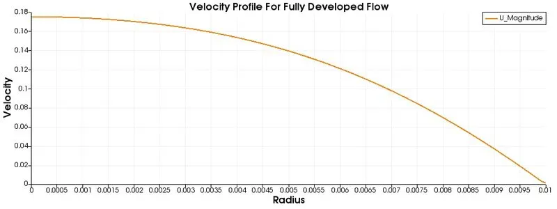
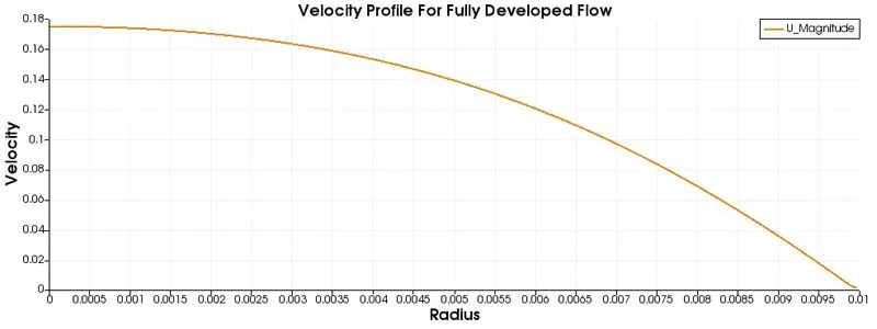
- The Velocity profile for fully developed Flow at distance 2.3
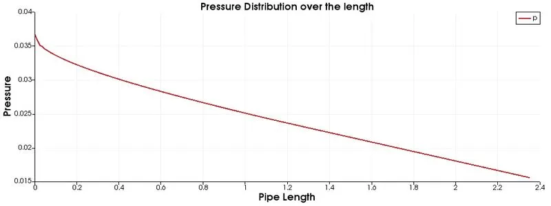
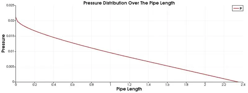
- The Pressure Distribution over the whole length of the pipe
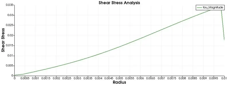
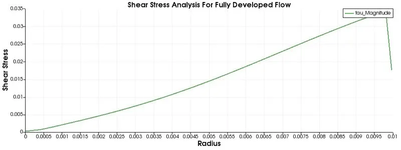
- The wall shear stress plot for fully developed flow
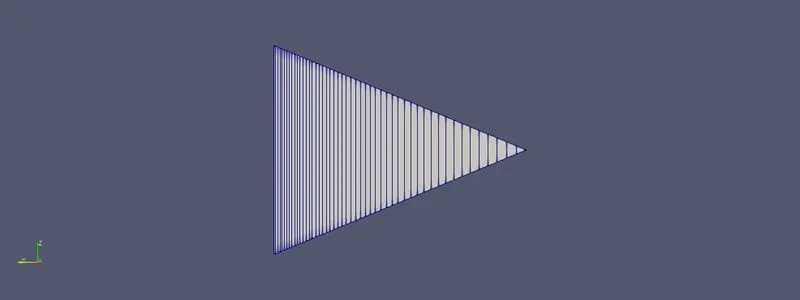
Now we create the geometry for 25 degree and 45 degree in same way just like for 10 degree
For 25 degree wedge angle the vertices are
vertices
(

	(0.000000 0.000000 0.000000)
	(0.000000 0.009763 0.002164)
	(0.000000 0.009763 -0.002164)
	(2.350000 0.000000 0.000000)
	(2.350000 0.009763 0.002164)
	(2.350000 0.009763 -0.002164)

);
For 45 degree wedge angle the vertices are
vertices
(

	(0.000000 0.000000 0.000000)
	(0.000000 0.009239 0.003827)
	(0.000000 0.009239 -0.003827)
	(2.350000 0.000000 0.000000)
	(2.350000 0.009239 0.003827)
	(2.350000 0.009239 -0.003827)

);
And all other files(like blockMeshDict file except the vertices, Kinematic Pressure file, Velocity file, transportProperties file and the controldict file) for 25 degree and 45 degree are as same as 10 degree wedge angle.
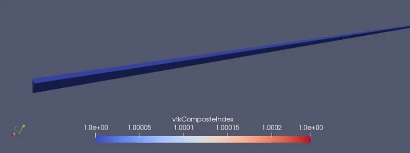
For 25 degree the geometry loooks like
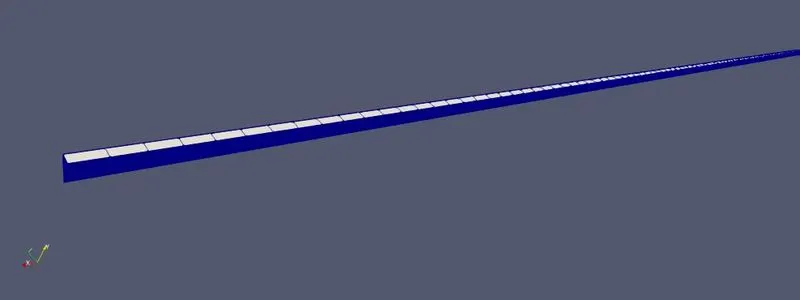
For 45 degree the geometry loooks like
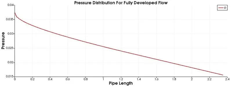
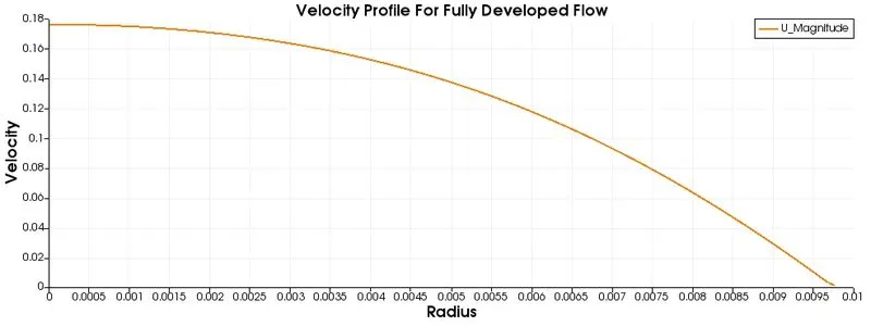
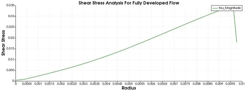
The solutions for 25 degree wedge angle
- The Pressure plot over the whole length of the Pipe
- Velocity profile for fully developed flow at distance 2.3
- Shear Stress Analysis For Fully Developed Flow
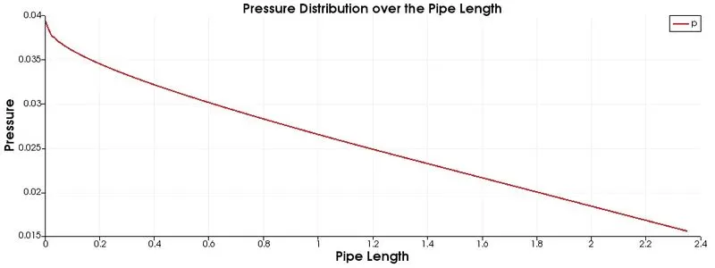
The solutions for 45 degree angle
- The Pressure plot over the whole length of the Pipe
- Velocity profile for fully developed flow at distance 2.3
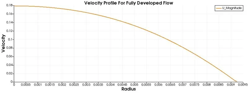
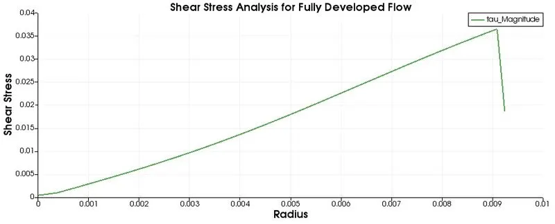
- Shear Stress Analysis For Fully Developed Flow
Case-2:- Symmetry Boundary Condition
Here we replaced the wedge boundary condition to symmetry boundary condition.
	front
	{
		type symmetry;
		faces
		(
			(0 3 4 1)
		);
	}
	back
	{
		type symmetry;
		faces
		(
			(0 2 5 3)
		);
	}
In each file where ever we wrote the wedge, we should replace it by symmetry. And now all files are okay for our simulation. Now we can see the results for 10 degree, 25 degree and 45 degree.
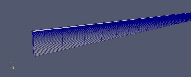
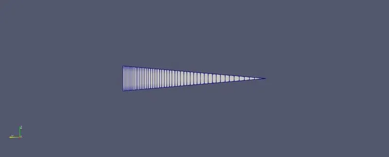
So after simulate the 10 degree wedge angle by using icoFoam solver, now we see the geometry and results
Geometry:-
Results:-
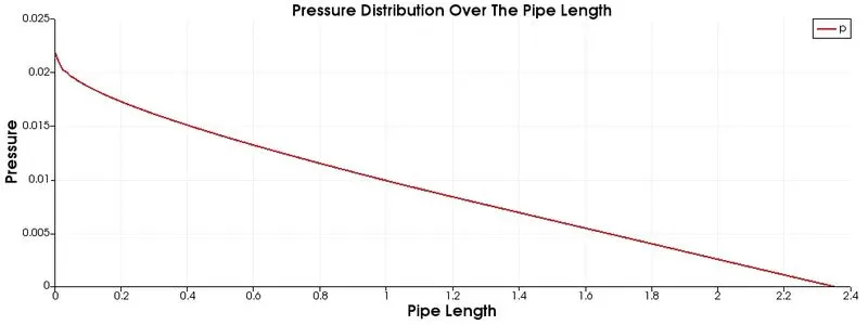
- Pressure Profile
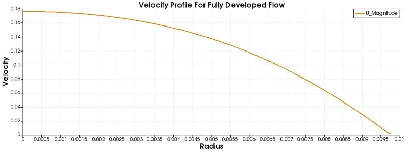
- Velocity Profile
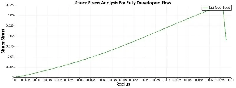
- Shear Stress Analysis
Similarly we see the geometry and result of 25 degree wedge angle
Geometry
Results
- Pressure Profile
- Velocity Profile
- Shear Stress Analysis For Fully Developed Flow
Now we see the geometry and result of 45 degree wedge angle
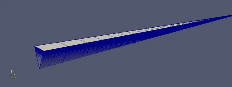
Geometry
Results
- Pressure Profile
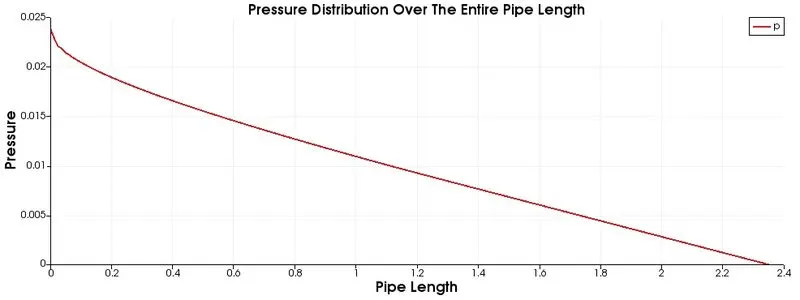
- Velocity Profile
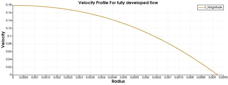
- Shear Stress Analysis For Fully Developed Flow
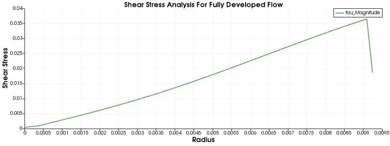
Validation Check By using H. P. equation:-
First we check the validation of 10 degree wedge angle
The matlab code for generate the numerical result
clear all;
close all;
clc;

Re = 2100;          % Reynolds number
Rho = 1000;         % Density of water
mu = 0.00089;       % Dynamic viscosity of water
nu = mu/Rho;        % Kinematic viscosity of water
D = 0.02;         % Diameter of the pipe
R = D/2;            % Radius of the pipe
ent_L = 0.05*Re*D;  % Entry length
theta = 10;          % Wedge angle in degree

%Boundery condition
V_avg = (nu*Re)/D;             %Average velocity
V_max = 2*V_avg;               % Maximum velocity
L = ent_L + 0.25;              %Length of the pipe
Dell_P = (32*mu*L*V_avg)/D^2;  % Pressure drop
kin_P = Dell_P/Rho;            % Kinematic pressure drop

r = linspace(0,R,100);
for i = 1:length(r)
    U(i) = 2*V_avg*(1-((r(i)^2)/(R^2)));
    tau(i) = 2*mu*V_max*(abs(r(i)))/R^2;
end
%shear stress
figs(1) = figure; % create first figure
plot(r,tau,"r","LineWidth",1.5)
xlabel("Radius","FontWeight","bold")
ylabel("Shear stress","FontWeight","bold")
title("Shear stress Analysis")
grid on;

%Velocity
figs(2) = figure;
plot(r,U,"g","LineWidth",1.5);
xlabel("Radius","FontWeight","bold")
ylabel("Velocity","FontWeight","bold")
title("Velocity Profile Validation Analysis")
grid on;
figs = findobj(0, 'type', 'figure');

for k=1:length(figs)
    % print each figure in figs to a separate .jpeg file
    print(figs(k), '-djpeg', sprintf('file%d.jpeg', k))
end- Velocity Validation For Fully Developed Flow
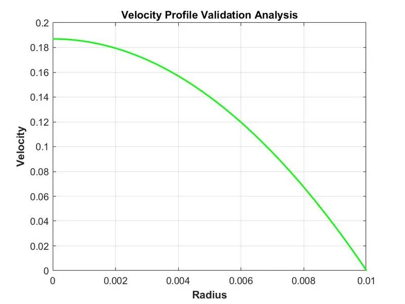
- Kinematic Pressure Value
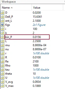
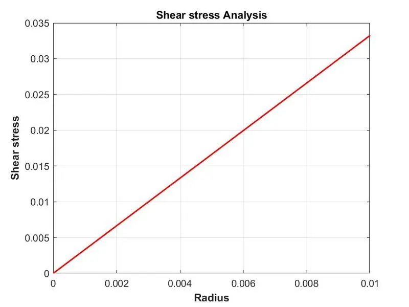
- Shear Stress Validation For Fully Developed Flow
Secondly we check the validation of 25 degree wedge angle
- Velocity Validation For Fully Developed Flow
- Kinematic Pressure Value
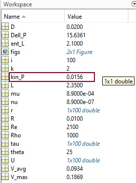
- Shear Stress Validation For Fully Developed Flow
Now we check the validation of 45 degree wedge angle
- Velocity Validation For Fully Developed Flow
- Kinematic Pressure Value
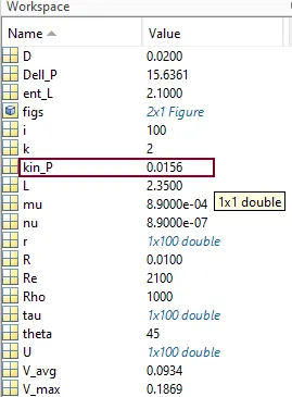
- Shear Stress Validation For Fully Developed Flow
CONCLUSION:-
- If we compare the both results of symmetry and wedge bondary condition we don't see many difference. The results are almost same.
- If we check the validation of results, for both case 10 degree wedge angle and 25 degree wedge angle analytical results are same as numerical results. In the case of analytical result of shear stress with the incresing of radius the shear sress increase, but after certain value of radius the shear stress decrease. It's nothing but OpenFoam calculation error.
- But for both case, for 45 degree wedge angle the analytical results and the numerical results having some difference. It has little error.
- The wedge boundary condition (BC) is used to define an axisymmetric situation. The model and flow must be axisymmetric along a central line such that all physical variables of the flow have the same value and distribution at a given radius for all angles.
- Wedge is different from Symmetry Boundary Condition in the sense that the wedge BC applies the Navier-Stokes equations in cylindrical coordinates whereas the latter applies in cartesian coordinates. One big advantage of a wedge is that it allows for the rotational flow around the axis and this is possible only because the fluxes and normal components are not assumed as zero.
- Symmetry Boundary condition is used to mirror the geometry.