Week 12 - Validation studies of Symmetry BC vs Wedge BC in OpenFOAM vs Analytical H.P equation
Objective :
- To simulate an axi-symmetric flow by applying the wedge and symmetry boundary condition for the wedge angles of 10, 25 and 45 degree respectively.
- The flow is laminar and flows through a constant cross-section pipe at an inlet Reynold's number of 2100.
- The flow can be transient or steady state simulation and to validate your results with the Hagen- Poiseuille's equations for the fully developed flow.
- To write code in Matlab to automate the generation of blockMeshDict file. The code should take inputs like pipe length, diameter, wedge angle, etc and output a fully functional blockMeshDict file.
Expected Results :
- Validate Hydro-dynamic length with the numerical result.
- Validate the fully developed flow velocity profile with its analytical profile.
- Validate maximum velocity and pressured drop for fully developed flow.
- Post-process Shear stress and validate wall shear stress for fully developed flow.
Specification :
Working fluid = water
Reynolds number = 2100
Diameter D = 0.02m
Radius R = 0.01m
Dynamic viscosity of water at 25 degree celcius - mu = 0.0008900`(Ns)/(m^2)`
Water density at 25 deg celcius = 997`(kg)/(m^3)`
Temperature of water = 25 degree celcius.
Theory :
The hagen -poiseuille equation describes the parabolic velocity profile of frictional, laminar pipe flows of in compressible, Newtonian fluids.When a fluid is moving through a pipe velocity will be varying in the radial direction in a particular manner. This is because of the pressence of fluid boundary friction, which may be otherwise stated as no-slip condition. We know that as the fluid moves downstream boundary layer gets thickened and finally, at a particuar location, it fills the entire pipe. Downstream of this point velocity profile will be parabolic. The entrance length can be defined as the distance between the above-mentioned point and the inlet of pipe.
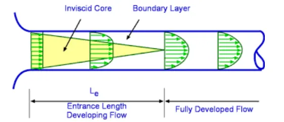
In the above figure, it is clear that the flow is developing in the entrance region and after the entrance region the flow is fully developed and thereafter there are no charges in the velocity profile. Viscous forces are responsible for the velocity profiles.
Calculations :
Entrance Length of Laminar flow pipe is calculated vy th equation `(L_e/D)` = 0.06 .Re
Entrance length = `L_e = 0.06. R_e . D`
= 2.52 m
Total length `L_t`= `L_e`+0.3
Total length `L_t` = 2.82m
Mean velocity `V_(mean)` = `(R_e. mu)/(rho.D)`
= 0.09373m/s.
Maximum Velocity `V_(max) = 2.V_(mean)`
= 0.18746 m/s
Pressure Drop`triangleP` = `(32. mu . V_(mean) . (L_t - L_e))/D^2`
= 2 pa
Kinematic pressure `(P_k)` = `(triangleP)/rho`
= 2.008e-03`m^2 / sec^2`
Velocity profile u(r) = 2.`V_(mean)``(1-(r^2)/(R^2))``m^2 / sec^2`
The velocity is maximum at the center of the pipe and zero at the walls due to the no slip condition near walls.
Shear stress `tau = (2*mu*V_max*r)/(R^2)` `N/m^2`
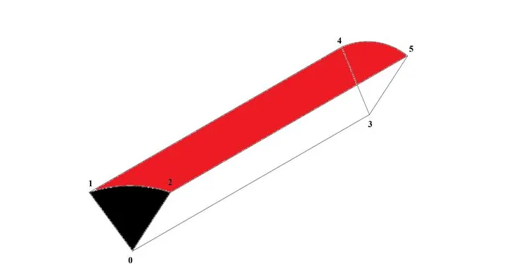
Wedge diagram :
Procedure :
- Firstly open the terminal in linux operating system by simply right clicking and selecting open terminal option or else we can use a short cut key Ctrl+Alt+t.
- Then in that type 'tut' which directs to the tutorial folder.
- Then type 'ls' which shows the list of options available in the tutorial folder, In that select 'incompressible' flow which is our objective.
- Then again type 'ls' then select 'icoFoam' which is actually suitable for laminar nonviscous flows.
- Then again type 'ls' then select the 'cavity' folder in cavity folder again we are going to see another 'cavity' folder there we define fluid domain and generate block mesh. But we are not going to make changes in the tutorial section first of all open foam doesn't allow to makes changes directly in the tutorial folder because it will corrupt the openfoam we need to reinstall it again in order to rectify that issue.
- so we are going to copy this cavity folder using 'cp -r cavity' command and paste it in openfoam run folder by typing 'cp -r cavity $FOAM_RUN/ cavity_test'. And then open run folder by typing 'cd $FOAM_RUN'. Where we can see cavity_test file.
- Now we can make any changes to the cavity_test file, which will never affect the openfoam official files. open cavity-test folder. Here we can provide specification for our block mesh in the sytem folder.
- Then provide starting time and ending time and the value of deltat in the controldict folder in order to calculate the cfl number. Note we need to choose the value of deltat which satisfies the CFL stability criteria which is it should be less than 1 in order to provide a stable solution. If it doesn't satisfy the solution will get blowedup at any stage. Instead of converging the solution got diverged.
- Then provide initial and boundary condition for velocity and pressure in '0' folder which is present inside the cavity test folder.
- A matlab code is generated which will recieve the wedge angle and mesh parameters from the user and give a blockMeshDict for the same as output which can be used for simulation in open foam.
Program :
Matlab file :
For wedge boundary condition :
clear all
close all
clc

%Input
Re = 2100;
D = 0.02;
R = D/2;
theta = input('Enter the wedge angle :\n');
mu = 0.89e-3;
rho = 997;
nu = mu/rho;

% Analytical velocity, pressure

L_e = 0.06*Re*D;
L_t = L_e + 0.3;
Vavg = (Re*mu)/(rho*D);
Vmax = 2*Vavg;
Del_P = (32*mu*Vavg*L_t)/D^2;
kin_P = Del_P/rho;

% Finding vertices
v0 = [0 0 0];
v1 = [0 R*cosd(theta/2) R*sind(theta/2)];
v2 = [0 R*cosd(theta/2) -R*sind(theta/2)];
v3 = [L_t 0 0];
v4 = [L_t R*cosd(theta/2) R*sind(theta/2)];
v5 = [L_t R*cosd(theta/2) -R*sind(theta/2)];


% BlocMeshDict file

f1 = fopen('blockMeshDict.txt','w');

fprintf(f1,'%s \n','/*--------------------------------*- C++ -*----------------------------------*\');
fprintf(f1,'%s \n','  =========                 |');
fprintf(f1,'%s \n','  \\      /  F ield         | OpenFOAM: The Open Source CFD Toolbox');
fprintf(f1,'%s \n','   \\    /   O peration     | Website:  https://openfoam.org');
fprintf(f1,'%s \n','    \\  /    A nd           | Version:  9');
fprintf(f1,'%s \n','     \\/     M anipulation  |');
fprintf(f1,'%s \n','\*---------------------------------------------------------------------------*/');
fprintf(f1,'%s \n','FoamFile');
fprintf(f1,'%s \n','{');
fprintf(f1,'%s \n','    format      ascii;');
fprintf(f1,'%s \n','    class       dictionary;');
fprintf(f1,'%s \n','    object      blockMeshDict;');
fprintf(f1,'%s \n','}');
fprintf(f1,'%s \n','// * * * * * * * * * * * * * * * * * * * * * * * * * * * * * * * * * * * * * //');
fprintf(f1,'\n');
fprintf(f1,'%s \n','convertToMeters 1;');
fprintf(f1,'\n');

% vertices
fprintf(f1,'vertices \n');
fprintf(f1,'(\n');
fprintf(f1,blanks(4),'%s \n','(');
v0 = fprintf(f1,'(%f %f %f) \n',v0(1),v0(2),v0(3));
fprintf(f1,blanks(4),'%s','(');
v1 = fprintf(f1,'(%f %f %f) \n',v1(1),v1(2),v1(3));
fprintf(f1,blanks(4),'%s','(');
v2 = fprintf(f1,'(%f %f %f) \n',v2(1),v2(2),v2(3));
fprintf(f1,blanks(4),'%s','(');
v3 = fprintf(f1,'(%f %f %f) \n',v3(1),v3(2),v3(3));
fprintf(f1,blanks(4),'%s','(');
v4 = fprintf(f1,'(%f %f %f) \n',v4(1),v4(2),v4(3));
fprintf(f1,blanks(4),'%s','(');
v5 = fprintf(f1,'(%f %f %f) \n',v5(1),v5(2),v5(3));
fprintf(f1,'\n);\n');

% block creation

fprintf(f1,'\nblocks\n');

fprintf(f1,'(\n');
fprintf(f1,blanks(4),'%s','(');
fprintf(f1,'%s','hex (0 3 5 2 0 3 4 1)');

% Mesh generation
m1 = input('Enter the number of mesh along x-axis :\n');
m2 = input('Enter the number of mesh along y-axis :\n');
m3 = input('Enter the number of mesh along z-axis :\n');

fprintf(f1,blanks(1),'%s \n','(');
fprintf(f1, '(%d %d %d)',m1,m2,m3);
fprintf(f1,'%s',' simpleGrading (1 0.2 1)');
fprintf(f1,'\n);');

% edge creation

fprintf(f1,'\n\nedges\n');
fprintf(f1,'(\n');
fprintf(f1,'%s\n arc 1 2 (0 %f 0)',blanks(1),R);
fprintf(f1,'%s\n arc 4 5 (%f %f 0)',blanks(1),L_t,R);
fprintf(f1,'\n\n);');

% Apply boundary conditions

% inlet

fprintf(f1,'\n\nboundary\n(\n');
fprintf(f1,'%s',' inlet');
fprintf(f1, '\n {\n');
fprintf(f1,'%s',blanks(10),'type patch;');
fprintf(f1,'\n');
fprintf(f1,'%s',blanks(10),'faces');
fprintf(f1,'\n');
fprintf(f1,'%s',blanks(10),'(');
fprintf(f1,'\n');
fprintf(f1,'%s',blanks(13),'(0 1 2 0)');
fprintf(f1,'\n');
fprintf(f1,'%s',blanks(10),');');
fprintf(f1,'\n  }\n');

% outlet
fprintf(f1,'\n');
fprintf(f1,'%s',' outlet');
fprintf(f1, '\n {\n');
fprintf(f1,'%s',blanks(10),'type patch;');
fprintf(f1,'\n');
fprintf(f1,'%s',blanks(10),'faces');
fprintf(f1,'\n');
fprintf(f1,'%s',blanks(10),'(');
fprintf(f1,'\n');
fprintf(f1,'%s',blanks(13),'(3 5 4 3)');
fprintf(f1,'\n');
fprintf(f1,'%s',blanks(10),');');
fprintf(f1,'\n  }\n');

% Topwall
fprintf(f1,'\n');
fprintf(f1,'%s',' topwall');
fprintf(f1, '\n {\n');
fprintf(f1,'%s',blanks(10),'type wall;');
fprintf(f1,'\n');
fprintf(f1,'%s',blanks(10),'faces');
fprintf(f1,'\n');
fprintf(f1,'%s',blanks(10),'(');
fprintf(f1,'\n');
fprintf(f1,'%s',blanks(13),'(1 4 5 2)');
fprintf(f1,'\n');
fprintf(f1,'%s',blanks(10),');');
fprintf(f1,'\n  }\n\n');

% front
fprintf(f1,'\n');
fprintf(f1,'%s',' front');
fprintf(f1, '\n {\n');
fprintf(f1,'%s',blanks(10),'type wedge;');
fprintf(f1,'\n');
fprintf(f1,'%s',blanks(10),'faces');
fprintf(f1,'\n');
fprintf(f1,'%s',blanks(10),'(');
fprintf(f1,'\n');
fprintf(f1,'%s',blanks(13),'(0 3 4 1)');
fprintf(f1,'\n');
fprintf(f1,'%s',blanks(10),');');
fprintf(f1,'\n  }\n');

% back
fprintf(f1,'\n');
fprintf(f1,'%s',' back');
fprintf(f1, '\n {\n');
fprintf(f1,'%s',blanks(10),'type wedge;');
fprintf(f1,'\n');
fprintf(f1,'%s',blanks(10),'faces');
fprintf(f1,'\n');
fprintf(f1,'%s',blanks(10),'(');
fprintf(f1,'\n');
fprintf(f1,'%s',blanks(13),'(0 2 5 3)');
fprintf(f1,'\n');
fprintf(f1,'%s',blanks(10),');');
fprintf(f1,'\n  }\n');


% axis
fprintf(f1,'\n');
fprintf(f1,'%s',' axis');
fprintf(f1, '\n {\n');
fprintf(f1,'%s',blanks(10),'type empty;');
fprintf(f1,'\n');
fprintf(f1,'%s',blanks(10),'faces');
fprintf(f1,'\n');
fprintf(f1,'%s',blanks(10),'(');
fprintf(f1,'\n');
fprintf(f1,'%s',blanks(13),'(0 3 3 0)');
fprintf(f1,'\n');
fprintf(f1,'%s',blanks(10),');');
fprintf(f1,'\n  }\n\n');

fprintf(f1,'\n);\n');

fprintf(f1,'\nmergePatchPairs');
fprintf(f1,'\n(\n);\n\n');

fprintf(f1,'%s','// ************************************************************************* //');
fclose(f1);
BlockMeshDict file :
For wedge angle of 10 degree :
/*--------------------------------*- C++ -*----------------------------------*\
  =========                 |
  \\      /  F ield         | OpenFOAM: The Open Source CFD Toolbox
   \\    /   O peration     | Website:  https://openfoam.org
    \\  /    A nd           | Version:  9
     \\/     M anipulation  |
\*---------------------------------------------------------------------------*/
FoamFile
{
    format      ascii;
    class       dictionary;
    object      blockMeshDict;
}
// * * * * * * * * * * * * * * * * * * * * * * * * * * * * * * * * * * * * * //

convertToMeters 1;

vertices
(
    (0.000000 0.000000 0.000000)
    (0.000000 0.009962 0.000872)
    (0.000000 0.009962 -0.000872)
    (2.820000 0.000000 0.000000)
    (2.820000 0.009962 0.000872)
    (2.820000 0.009962 -0.000872)

);

blocks
(
    hex (0 3 5 2 0 3 4 1) (200 20 1) simpleGrading (1 0.2 1)
);

edges
(

 arc 1 2 (0 0.010000 0)
 arc 4 5 (2.820000 0.010000 0)

);

boundary
(
 inlet
 {
          type patch;
          faces
          (
             (0 1 2 0)
          );
  }

 outlet
 {
          type patch;
          faces
          (
             (3 5 4 3)
          );
  }

 topwall
 {
          type wall;
          faces
          (
             (1 4 5 2)
          );
  }


 front
 {
          type wedge;
          faces
          (
             (0 3 4 1)
          );
  }

 back
 {
          type wedge;
          faces
          (
             (0 2 5 3)
          );
  }

 axis
 {
          type empty;
          faces
          (
             (0 3 3 0)
          );
  }


);

mergePatchPairs
(
);

// ************************************************************************* //
For wedge angle of 25 degree :
/*--------------------------------*- C++ -*----------------------------------*\
  =========                 |
  \\      /  F ield         | OpenFOAM: The Open Source CFD Toolbox
   \\    /   O peration     | Website:  https://openfoam.org
    \\  /    A nd           | Version:  9
     \\/     M anipulation  |
\*---------------------------------------------------------------------------*/
FoamFile
{
    format      ascii;
    class       dictionary;
    object      blockMeshDict;
}
// * * * * * * * * * * * * * * * * * * * * * * * * * * * * * * * * * * * * * //

convertToMeters 1;

vertices
(
    (0.000000 0.000000 0.000000)
    (0.000000 0.009763 0.002164)
    (0.000000 0.009763 -0.002164)
    (2.820000 0.000000 0.000000)
    (2.820000 0.009763 0.002164)
    (2.820000 0.009763 -0.002164)

);

blocks
(
    hex (0 3 5 2 0 3 4 1) (200 20 1) simpleGrading (1 0.2 1)
);

edges
(

 arc 1 2 (0 0.010000 0)
 arc 4 5 (2.820000 0.010000 0)

);

boundary
(
 inlet
 {
          type patch;
          faces
          (
             (0 1 2 0)
          );
  }

 outlet
 {
          type patch;
          faces
          (
             (3 5 4 3)
          );
  }

 topwall
 {
          type wall;
          faces
          (
             (1 4 5 2)
          );
  }


 front
 {
          type wedge;
          faces
          (
             (0 3 4 1)
          );
  }

 back
 {
          type wedge;
          faces
          (
             (0 2 5 3)
          );
  }

 axis
 {
          type empty;
          faces
          (
             (0 3 3 0)
          );
  }


);

mergePatchPairs
(
);

// ************************************************************************* //
For wedge angle of 45 degree :
/*--------------------------------*- C++ -*----------------------------------*\
  =========                 |
  \\      /  F ield         | OpenFOAM: The Open Source CFD Toolbox
   \\    /   O peration     | Website:  https://openfoam.org
    \\  /    A nd           | Version:  9
     \\/     M anipulation  |
\*---------------------------------------------------------------------------*/
FoamFile
{
    format      ascii;
    class       dictionary;
    object      blockMeshDict;
}
// * * * * * * * * * * * * * * * * * * * * * * * * * * * * * * * * * * * * * //

convertToMeters 1;

vertices
(
    (0.000000 0.000000 0.000000)
    (0.000000 0.009239 0.003827)
    (0.000000 0.009239 -0.003827)
    (2.820000 0.000000 0.000000)
    (2.820000 0.009239 0.003827)
    (2.820000 0.009239 -0.003827)

);

blocks
(
    hex (0 3 5 2 0 3 4 1) (200 20 1) simpleGrading (1 0.2 1)
);

edges
(

 arc 1 2 (0 0.010000 0)
 arc 4 5 (2.820000 0.010000 0)

);

boundary
(
 inlet
 {
          type patch;
          faces
          (
             (0 1 2 0)
          );
  }

 outlet
 {
          type patch;
          faces
          (
             (3 5 4 3)
          );
  }

 topwall
 {
          type wall;
          faces
          (
             (1 4 5 2)
          );
  }


 front
 {
          type wedge;
          faces
          (
             (0 3 4 1)
          );
  }

 back
 {
          type wedge;
          faces
          (
             (0 2 5 3)
          );
  }

 axis
 {
          type empty;
          faces
          (
             (0 3 3 0)
          );
  }


);

mergePatchPairs
(
);

// ************************************************************************* //
ControlDict file :
/*--------------------------------*- C++ -*----------------------------------*\
  =========                 |
  \\      /  F ield         | OpenFOAM: The Open Source CFD Toolbox
   \\    /   O peration     | Website:  https://openfoam.org
    \\  /    A nd           | Version:  9
     \\/     M anipulation  |
\*---------------------------------------------------------------------------*/
FoamFile
{
    format      ascii;
    class       dictionary;
    location    "system";
    object      controlDict;
}
// * * * * * * * * * * * * * * * * * * * * * * * * * * * * * * * * * * * * * //

application     icoFoam;

startFrom       startTime;

startTime       0;

stopAt          endTime;

endTime         5;

deltaT          0.01;

writeControl    timeStep;

writeInterval   20;

purgeWrite      0;

writeFormat     ascii;

writePrecision  6;

writeCompression off;

timeFormat      general;

timePrecision   6;

runTimeModifiable true;


// ************************************************************************* //
Boundary and initial conditions :
Pressure file :
/*--------------------------------*- C++ -*----------------------------------*\
  =========                 |
  \\      /  F ield         | OpenFOAM: The Open Source CFD Toolbox
   \\    /   O peration     | Website:  https://openfoam.org
    \\  /    A nd           | Version:  9
     \\/     M anipulation  |
\*---------------------------------------------------------------------------*/
FoamFile
{
    format      ascii;
    class       volScalarField;
    object      p;
}
// * * * * * * * * * * * * * * * * * * * * * * * * * * * * * * * * * * * * * //

dimensions      [0 2 -2 0 0 0 0];

internalField   uniform 0;

boundaryField
{
    inlet
    {
        type            zeroGradient;
    }

    outlet
    {
        type            fixedValue;
        value           uniform 0;
    }

    topwall
    {
        type            zeroGradient;
    }

    front
    {
        type            wedge;
    }

    back
    {
        type            wedge;
    }

    axis
    {
        type            empty;
    }
}

// ************************************************************************* //
Velocity file :
/*--------------------------------*- C++ -*----------------------------------*\
  =========                 |
  \\      /  F ield         | OpenFOAM: The Open Source CFD Toolbox
   \\    /   O peration     | Website:  https://openfoam.org
    \\  /    A nd           | Version:  9
     \\/     M anipulation  |
\*---------------------------------------------------------------------------*/
FoamFile
{
    format      ascii;
    class       volVectorField;
    object      U;
}
// * * * * * * * * * * * * * * * * * * * * * * * * * * * * * * * * * * * * * //

dimensions      [0 1 -1 0 0 0 0];

internalField   uniform (0 0 0);

boundaryField
{
    inlet
    {
        type            fixedValue;
        value           uniform (0.09 0 0);
    }

    outlet
    {
        type            zeroGradient;
    }

    topwall
    {
        type            noSlip;
    }

    front
    {
        type            wedge;
    }

    back
    {
        type            wedge;
    }

    axis
    {
        type            empty;
    }
}

// ************************************************************************* //
Transportproperties file :
/*--------------------------------*- C++ -*----------------------------------*\
  =========                 |
  \\      /  F ield         | OpenFOAM: The Open Source CFD Toolbox
   \\    /   O peration     | Website:  https://openfoam.org
    \\  /    A nd           | Version:  9
     \\/     M anipulation  |
\*---------------------------------------------------------------------------*/
FoamFile
{
    format      ascii;
    class       dictionary;
    location    "constant";
    object      transportProperties;
}
// * * * * * * * * * * * * * * * * * * * * * * * * * * * * * * * * * * * * * //

nu              [0 2 -1 0 0 0 0] 0.892e-6;


// ************************************************************************* //
For symmetry boundary condition :
Matlab file :
clear all
close all
clc

%Input
Re = 2100;
D = 0.02;
R = D/2;
theta = input('Enter the wedge angle :\n');
mu = 0.89e-3;
rho = 997;
nu = mu/rho;

% Analytical velocity, pressure

L_e = 0.06*Re*D;
L_t = L_e + 0.3;
Vavg = (Re*mu)/(rho*D);
Vmax = 2*Vavg;
Del_P = (32*mu*Vavg*L_t)/D^2;
kin_P = Del_P/rho;

% Shear stress
r = linspace(-0.01,0.01,10);
for i = 1:length(r)
    tau(i) = (2*mu*Vmax*abs(r(i)))/(R^2);
end
plot(r,tau,'linewidth',2)
xlabel('Radius of pipe in meter')
ylabel('Shear stress in newton per meter square')
title('Change in shear stress for the radius along along the pipe')

% Finding vertices
v0 = [0 0 0];
v1 = [0 R*cosd(theta/2) R*sind(theta/2)];
v2 = [0 R*cosd(theta/2) -R*sind(theta/2)];
v3 = [L_t 0 0];
v4 = [L_t R*cosd(theta/2) R*sind(theta/2)];
v5 = [L_t R*cosd(theta/2) -R*sind(theta/2)];


% BlocMeshDict file

f1 = fopen('blockMeshDict.txt','w');

fprintf(f1,'%s \n','/*--------------------------------*- C++ -*----------------------------------*\');
fprintf(f1,'%s \n','  =========                 |');
fprintf(f1,'%s \n','  \\      /  F ield         | OpenFOAM: The Open Source CFD Toolbox');
fprintf(f1,'%s \n','   \\    /   O peration     | Website:  https://openfoam.org');
fprintf(f1,'%s \n','    \\  /    A nd           | Version:  9');
fprintf(f1,'%s \n','     \\/     M anipulation  |');
fprintf(f1,'%s \n','\*---------------------------------------------------------------------------*/');
fprintf(f1,'%s \n','FoamFile');
fprintf(f1,'%s \n','{');
fprintf(f1,'%s \n','    format      ascii;');
fprintf(f1,'%s \n','    class       dictionary;');
fprintf(f1,'%s \n','    object      blockMeshDict;');
fprintf(f1,'%s \n','}');
fprintf(f1,'%s \n','// * * * * * * * * * * * * * * * * * * * * * * * * * * * * * * * * * * * * * //');
fprintf(f1,'\n');
fprintf(f1,'%s \n','convertToMeters 1;');
fprintf(f1,'\n');

% vertices
fprintf(f1,'vertices \n');
fprintf(f1,'(\n');
fprintf(f1,blanks(4),'%s \n','(');
v0 = fprintf(f1,'(%f %f %f) \n',v0(1),v0(2),v0(3));
fprintf(f1,blanks(4),'%s','(');
v1 = fprintf(f1,'(%f %f %f) \n',v1(1),v1(2),v1(3));
fprintf(f1,blanks(4),'%s','(');
v2 = fprintf(f1,'(%f %f %f) \n',v2(1),v2(2),v2(3));
fprintf(f1,blanks(4),'%s','(');
v3 = fprintf(f1,'(%f %f %f) \n',v3(1),v3(2),v3(3));
fprintf(f1,blanks(4),'%s','(');
v4 = fprintf(f1,'(%f %f %f) \n',v4(1),v4(2),v4(3));
fprintf(f1,blanks(4),'%s','(');
v5 = fprintf(f1,'(%f %f %f) \n',v5(1),v5(2),v5(3));
fprintf(f1,'\n);\n');

% block creation

fprintf(f1,'\nblocks\n');

fprintf(f1,'(\n');
fprintf(f1,blanks(4),'%s','(');
fprintf(f1,'%s','hex (0 3 5 2 0 3 4 1)');

% Mesh generation
m1 = input('Enter the number of mesh along x-axis :\n');
m2 = input('Enter the number of mesh along y-axis :\n');
m3 = input('Enter the number of mesh along z-axis :\n');

fprintf(f1,blanks(1),'%s \n','(');
fprintf(f1, '(%d %d %d)',m1,m2,m3);
fprintf(f1,'%s',' simpleGrading (1 0.2 1)');
fprintf(f1,'\n);');

% edge creation

fprintf(f1,'\n\nedges\n');
fprintf(f1,'(\n');
fprintf(f1,'%s\n arc 1 2 (0 %f 0)',blanks(1),R);
fprintf(f1,'%s\n arc 4 5 (%f %f 0)',blanks(1),L_t,R);
fprintf(f1,'\n\n);');

% Apply boundary conditions

% inlet

fprintf(f1,'\n\nboundary\n(\n');
fprintf(f1,'%s',' inlet');
fprintf(f1, '\n {\n');
fprintf(f1,'%s',blanks(10),'type patch;');
fprintf(f1,'\n');
fprintf(f1,'%s',blanks(10),'faces');
fprintf(f1,'\n');
fprintf(f1,'%s',blanks(10),'(');
fprintf(f1,'\n');
fprintf(f1,'%s',blanks(13),'(0 1 2 0)');
fprintf(f1,'\n');
fprintf(f1,'%s',blanks(10),');');
fprintf(f1,'\n  }\n');

% outlet
fprintf(f1,'\n');
fprintf(f1,'%s',' outlet');
fprintf(f1, '\n {\n');
fprintf(f1,'%s',blanks(10),'type patch;');
fprintf(f1,'\n');
fprintf(f1,'%s',blanks(10),'faces');
fprintf(f1,'\n');
fprintf(f1,'%s',blanks(10),'(');
fprintf(f1,'\n');
fprintf(f1,'%s',blanks(13),'(3 5 4 3)');
fprintf(f1,'\n');
fprintf(f1,'%s',blanks(10),');');
fprintf(f1,'\n  }\n');

% Topwall
fprintf(f1,'\n');
fprintf(f1,'%s',' topwall');
fprintf(f1, '\n {\n');
fprintf(f1,'%s',blanks(10),'type wall;');
fprintf(f1,'\n');
fprintf(f1,'%s',blanks(10),'faces');
fprintf(f1,'\n');
fprintf(f1,'%s',blanks(10),'(');
fprintf(f1,'\n');
fprintf(f1,'%s',blanks(13),'(1 4 5 2)');
fprintf(f1,'\n');
fprintf(f1,'%s',blanks(10),');');
fprintf(f1,'\n  }\n\n');

% front
fprintf(f1,'\n');
fprintf(f1,'%s',' front');
fprintf(f1, '\n {\n');
fprintf(f1,'%s',blanks(10),'type symmetry;');
fprintf(f1,'\n');
fprintf(f1,'%s',blanks(10),'faces');
fprintf(f1,'\n');
fprintf(f1,'%s',blanks(10),'(');
fprintf(f1,'\n');
fprintf(f1,'%s',blanks(13),'(0 3 4 1)');
fprintf(f1,'\n');
fprintf(f1,'%s',blanks(10),');');
fprintf(f1,'\n  }\n');

% back
fprintf(f1,'\n');
fprintf(f1,'%s',' back');
fprintf(f1, '\n {\n');
fprintf(f1,'%s',blanks(10),'type symmetry;');
fprintf(f1,'\n');
fprintf(f1,'%s',blanks(10),'faces');
fprintf(f1,'\n');
fprintf(f1,'%s',blanks(10),'(');
fprintf(f1,'\n');
fprintf(f1,'%s',blanks(13),'(0 2 5 3)');
fprintf(f1,'\n');
fprintf(f1,'%s',blanks(10),');');
fprintf(f1,'\n  }\n');


% axis
fprintf(f1,'\n');
fprintf(f1,'%s',' axis');
fprintf(f1, '\n {\n');
fprintf(f1,'%s',blanks(10),'type empty;');
fprintf(f1,'\n');
fprintf(f1,'%s',blanks(10),'faces');
fprintf(f1,'\n');
fprintf(f1,'%s',blanks(10),'(');
fprintf(f1,'\n');
fprintf(f1,'%s',blanks(13),'(0 3 3 0)');
fprintf(f1,'\n');
fprintf(f1,'%s',blanks(10),');');
fprintf(f1,'\n  }\n\n');

fprintf(f1,'\n);\n');

fprintf(f1,'\nmergePatchPairs');
fprintf(f1,'\n(\n);\n\n');

fprintf(f1,'%s','// ************************************************************************* //');
fclose(f1);
BlockMeshDict file :
For wedge angle of 10 degree :
/*--------------------------------*- C++ -*----------------------------------*\
  =========                 |
  \\      /  F ield         | OpenFOAM: The Open Source CFD Toolbox
   \\    /   O peration     | Website:  https://openfoam.org
    \\  /    A nd           | Version:  9
     \\/     M anipulation  |
\*---------------------------------------------------------------------------*/
FoamFile
{
    format      ascii;
    class       dictionary;
    object      blockMeshDict;
}
// * * * * * * * * * * * * * * * * * * * * * * * * * * * * * * * * * * * * * //

convertToMeters 1;

vertices
(
    (0.000000 0.000000 0.000000)
    (0.000000 0.009962 0.000872)
    (0.000000 0.009962 -0.000872)
    (2.820000 0.000000 0.000000)
    (2.820000 0.009962 0.000872)
    (2.820000 0.009962 -0.000872)

);

blocks
(
    hex (0 3 5 2 0 3 4 1) (200 20 1) simpleGrading (1 0.2 1)
);

edges
(

 arc 1 2 (0 0.010000 0)
 arc 4 5 (2.820000 0.010000 0)

);

boundary
(
 inlet
 {
          type patch;
          faces
          (
             (0 1 2 0)
          );
  }

 outlet
 {
          type patch;
          faces
          (
             (3 5 4 3)
          );
  }

 topwall
 {
          type wall;
          faces
          (
             (1 4 5 2)
          );
  }


 front
 {
          type symmetry;
          faces
          (
             (0 3 4 1)
          );
  }

 back
 {
          type symmetry;
          faces
          (
             (0 2 5 3)
          );
  }

 axis
 {
          type empty;
          faces
          (
             (0 3 3 0)
          );
  }


);

mergePatchPairs
(
);

// ************************************************************************* //
For wedge angle of 25 degree :
/*--------------------------------*- C++ -*----------------------------------*\
  =========                 |
  \\      /  F ield         | OpenFOAM: The Open Source CFD Toolbox
   \\    /   O peration     | Website:  https://openfoam.org
    \\  /    A nd           | Version:  9
     \\/     M anipulation  |
\*---------------------------------------------------------------------------*/
FoamFile
{
    format      ascii;
    class       dictionary;
    object      blockMeshDict;
}
// * * * * * * * * * * * * * * * * * * * * * * * * * * * * * * * * * * * * * //

convertToMeters 1;

vertices
(
    (0.000000 0.000000 0.000000)
    (0.000000 0.009763 0.002164)
    (0.000000 0.009763 -0.002164)
    (2.820000 0.000000 0.000000)
    (2.820000 0.009763 0.002164)
    (2.820000 0.009763 -0.002164)

);

blocks
(
    hex (0 3 5 2 0 3 4 1) (200 20 1) simpleGrading (1 0.2 1)
);

edges
(

 arc 1 2 (0 0.010000 0)
 arc 4 5 (2.820000 0.010000 0)

);

boundary
(
 inlet
 {
          type patch;
          faces
          (
             (0 1 2 0)
          );
  }

 outlet
 {
          type patch;
          faces
          (
             (3 5 4 3)
          );
  }

 topwall
 {
          type wall;
          faces
          (
             (1 4 5 2)
          );
  }


 front
 {
          type symmetry;
          faces
          (
             (0 3 4 1)
          );
  }

 back
 {
          type symmetry;
          faces
          (
             (0 2 5 3)
          );
  }

 axis
 {
          type empty;
          faces
          (
             (0 3 3 0)
          );
  }


);

mergePatchPairs
(
);

// ************************************************************************* //
For wedge angle of 45 degree :
/*--------------------------------*- C++ -*----------------------------------*\
  =========                 |
  \\      /  F ield         | OpenFOAM: The Open Source CFD Toolbox
   \\    /   O peration     | Website:  https://openfoam.org
    \\  /    A nd           | Version:  9
     \\/     M anipulation  |
\*---------------------------------------------------------------------------*/
FoamFile
{
    format      ascii;
    class       dictionary;
    object      blockMeshDict;
}
// * * * * * * * * * * * * * * * * * * * * * * * * * * * * * * * * * * * * * //

convertToMeters 1;

vertices
(
    (0.000000 0.000000 0.000000)
    (0.000000 0.009239 0.003827)
    (0.000000 0.009239 -0.003827)
    (2.820000 0.000000 0.000000)
    (2.820000 0.009239 0.003827)
    (2.820000 0.009239 -0.003827)

);

blocks
(
    hex (0 3 5 2 0 3 4 1) (200 20 1) simpleGrading (1 0.2 1)
);

edges
(

 arc 1 2 (0 0.010000 0)
 arc 4 5 (2.820000 0.010000 0)

);

boundary
(
 inlet
 {
          type patch;
          faces
          (
             (0 1 2 0)
          );
  }

 outlet
 {
          type patch;
          faces
          (
             (3 5 4 3)
          );
  }

 topwall
 {
          type wall;
          faces
          (
             (1 4 5 2)
          );
  }


 front
 {
          type symmetry;
          faces
          (
             (0 3 4 1)
          );
  }

 back
 {
          type symmetry;
          faces
          (
             (0 2 5 3)
          );
  }

 axis
 {
          type empty;
          faces
          (
             (0 3 3 0)
          );
  }


);

mergePatchPairs
(
);

// ************************************************************************* //
ControlDict file :
/*--------------------------------*- C++ -*----------------------------------*\
  =========                 |
  \\      /  F ield         | OpenFOAM: The Open Source CFD Toolbox
   \\    /   O peration     | Website:  https://openfoam.org
    \\  /    A nd           | Version:  9
     \\/     M anipulation  |
\*---------------------------------------------------------------------------*/
FoamFile
{
    format      ascii;
    class       dictionary;
    location    "system";
    object      controlDict;
}
// * * * * * * * * * * * * * * * * * * * * * * * * * * * * * * * * * * * * * //

application     icoFoam;

startFrom       startTime;

startTime       0;

stopAt          endTime;

endTime         5;

deltaT          0.01;

writeControl    timeStep;

writeInterval   20;

purgeWrite      0;

writeFormat     ascii;

writePrecision  6;

writeCompression off;

timeFormat      general;

timePrecision   6;

runTimeModifiable true;


// ************************************************************************* //
Boundary conditions :
Velocity :
/*--------------------------------*- C++ -*----------------------------------*\
  =========                 |
  \\      /  F ield         | OpenFOAM: The Open Source CFD Toolbox
   \\    /   O peration     | Website:  https://openfoam.org
    \\  /    A nd           | Version:  9
     \\/     M anipulation  |
\*---------------------------------------------------------------------------*/
FoamFile
{
    format      ascii;
    class       volVectorField;
    object      U;
}
// * * * * * * * * * * * * * * * * * * * * * * * * * * * * * * * * * * * * * //

dimensions      [0 1 -1 0 0 0 0];

internalField   uniform (0 0 0);

boundaryField
{
    inlet
    {
        type            fixedValue;
        value           uniform (0.09 0 0);
    }

    outlet
    {
        type            zeroGradient;
    }

    topwall
    {
        type            noSlip;
    }

    front
    {
        type            symmetry;
    }

    back
    {
        type            symmetry;
    }

    axis
    {
        type            empty;
    }
}

// ************************************************************************* //
pressure :
/*--------------------------------*- C++ -*----------------------------------*\
  =========                 |
  \\      /  F ield         | OpenFOAM: The Open Source CFD Toolbox
   \\    /   O peration     | Website:  https://openfoam.org
    \\  /    A nd           | Version:  9
     \\/     M anipulation  |
\*---------------------------------------------------------------------------*/
FoamFile
{
    format      ascii;
    class       volScalarField;
    object      p;
}
// * * * * * * * * * * * * * * * * * * * * * * * * * * * * * * * * * * * * * //

dimensions      [0 2 -2 0 0 0 0];

internalField   uniform 0;

boundaryField
{
    inlet
    {
        type            zeroGradient;
    }

    outlet
    {
        type            fixedValue;
        value           uniform 0;
    }

    topwall
    {
        type            zeroGradient;
    }

    front
    {
        type            symmetry;
    }

    back
    {
        type            symmetry;
    }

    axis
    {
        type            empty;
    }
}

// ************************************************************************* //
Transportproperties file :
/*--------------------------------*- C++ -*----------------------------------*\
  =========                 |
  \\      /  F ield         | OpenFOAM: The Open Source CFD Toolbox
   \\    /   O peration     | Website:  https://openfoam.org
    \\  /    A nd           | Version:  9
     \\/     M anipulation  |
\*---------------------------------------------------------------------------*/
FoamFile
{
    format      ascii;
    class       dictionary;
    location    "constant";
    object      transportProperties;
}
// * * * * * * * * * * * * * * * * * * * * * * * * * * * * * * * * * * * * * //

nu              [0 2 -1 0 0 0 0] 0.892e-6;


// ************************************************************************* //
Output :
For wedge angle of 10 degree :
fig(a)
fig(b)
fig(c)
fig(d)
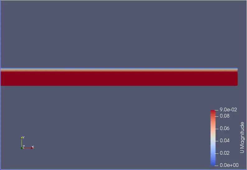
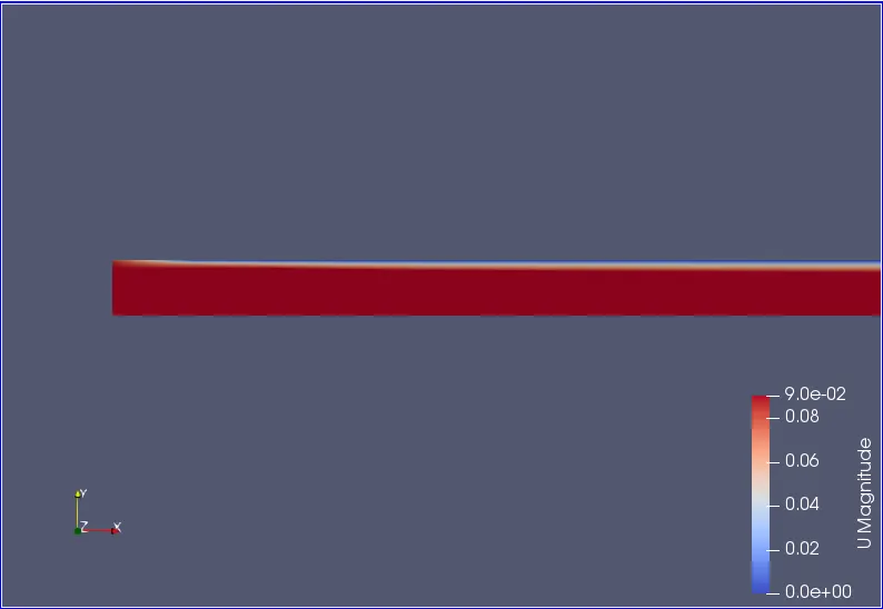
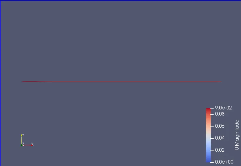
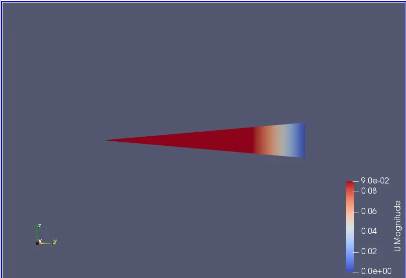
fig(a),fib(b),fig(c) and fig(d) shows the simulation of change in velocity with respect to the time step for the given length of pipe.
Change in pressure :
fig(e)
fig(f)
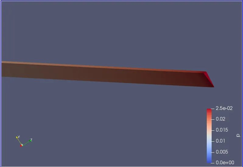
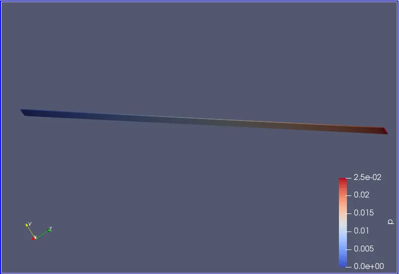
fig(e) and fig(f) shows the simulation of change in pressure with respect to the time step for the given length of pipe.
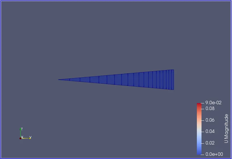
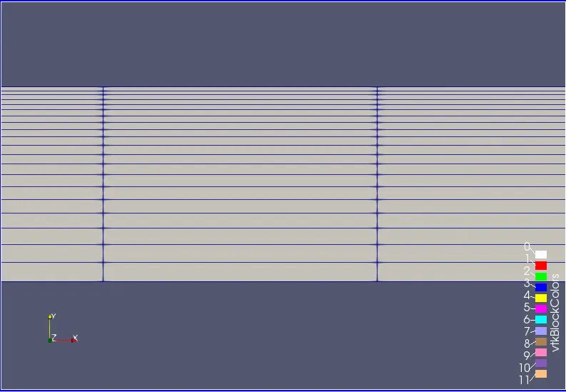
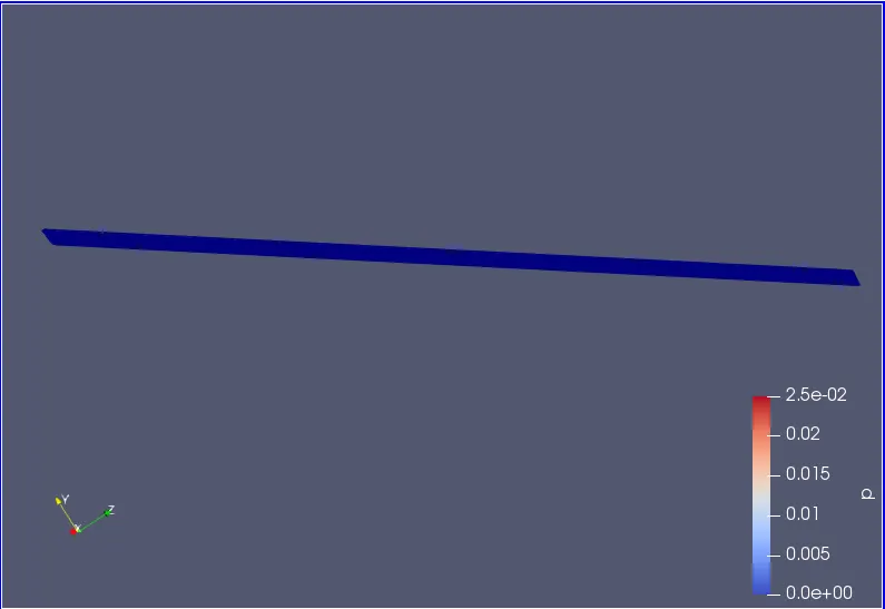
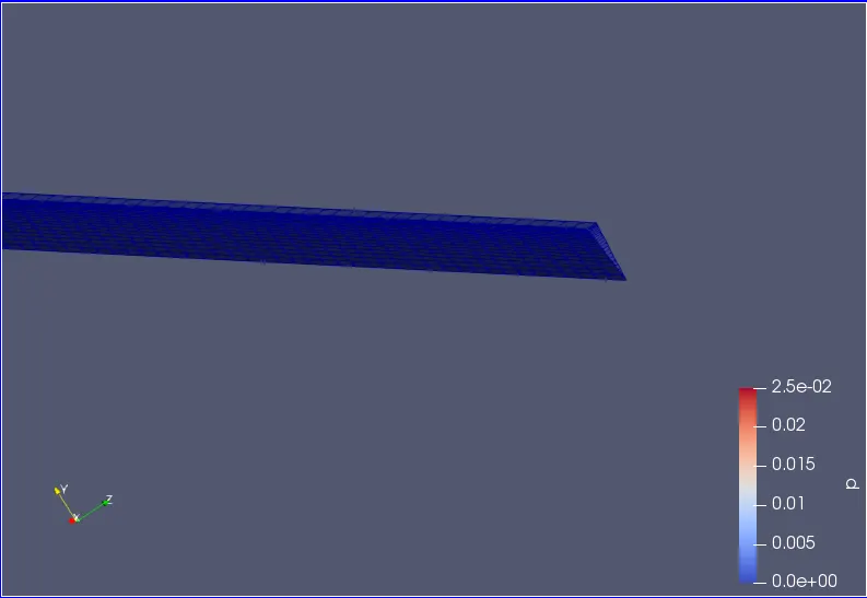
Mesh structure :
fig(g)
fig(h)
fig(i)
fig(j)
fig(g), fig(h), fig(i and fig(j)) shows the mesh structure of wedge for a pipe.
Change in velocity :
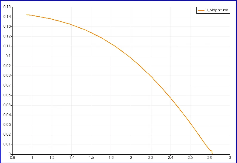
fig(k)
The above plot shows the change in velocity with respect to time step for the given length of the pipe which is for x=2.82m
Change in pressure :
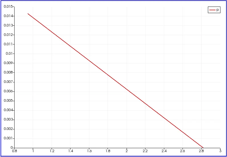
fig(l)
The above plot shows the change in pressure with respect to time step for the given length of the pipe which is for x=2.82m.
Change in shear stress :
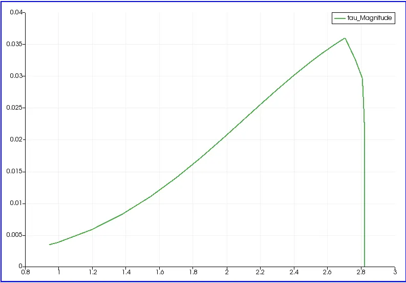
fig(m)
The above plot shows the change in shear stress with respect to time step for the given length of the pipe which is for x=2.82.
For wedge angle of 25 degree :
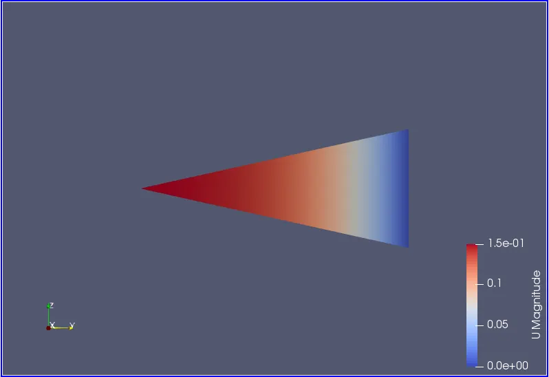
fig(n)
fig(n) shows the simulation of change in velocity with respect to the time step for the given length of pipe.
Change in pressure :
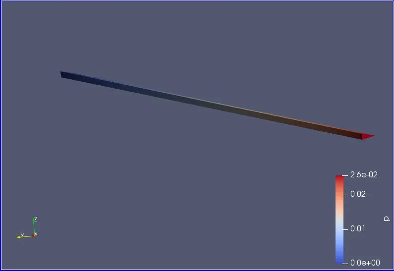
fig(o)
fig(o) shows the simulation of change in pressure with respect to the time step for the given length of pipe.
Mesh structure :
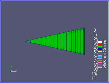
fig(p)
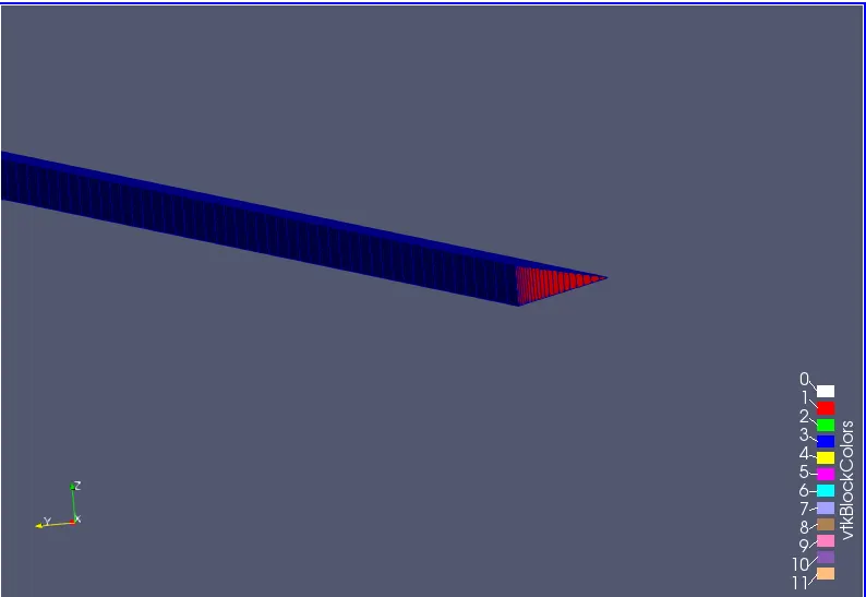
fig(q)
fig(p) and fig(q) shows the mesh structure of wedge for a pipe.
Change in velocity :
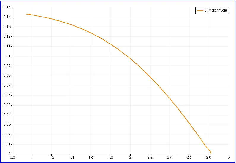
fig(r)
The above plot shows the change in velocity with respect to time step for the given length of the pipe which is for x=2.82m
Change in pressure :
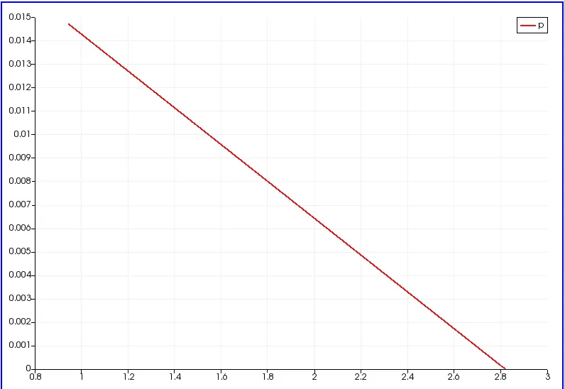
fig(s)
The above plot shows the change in pressure with respect to time step for the given length of the pipe which is for x=2.82m.
Change in shear stress :
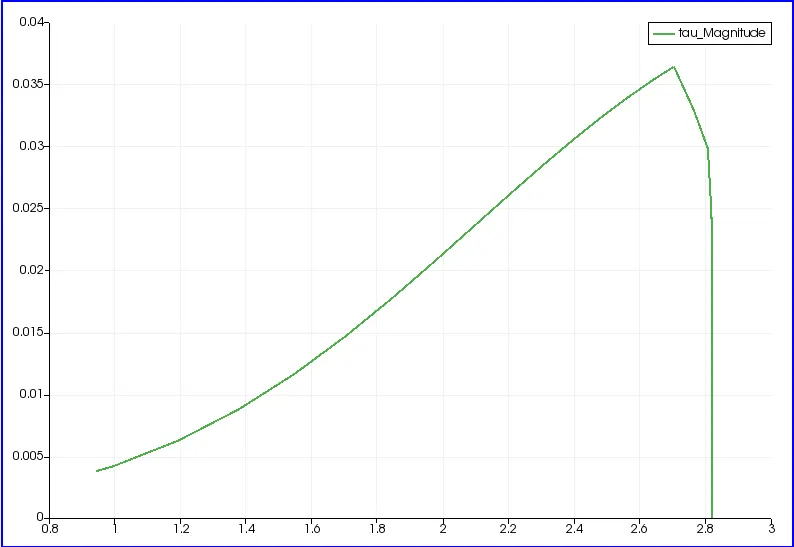
fig(t)
The above plot shows the change in shear stress with respect to time step for the given length of the pipe which is for x=2.82.
For wedge angle 45 degree :
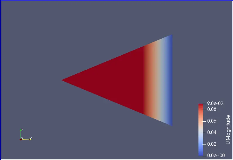
fig(u)
fig(u) shows the simulation of change in velocity with respect to the time step for the given length of pipe.
Change in pressure :
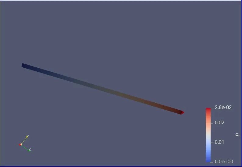
fig(v)
fig(v) shows the simulation of change in pressure with respect to the time step for the given length of pipe.
Mesh structure :
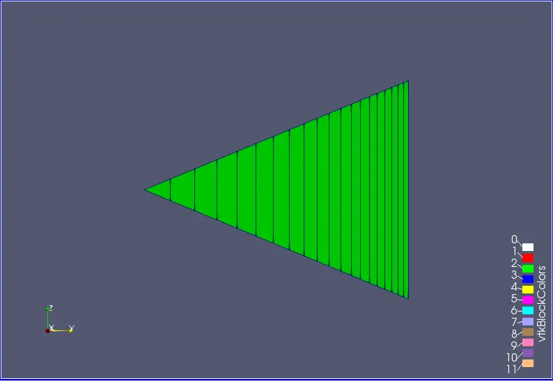
fig(w)
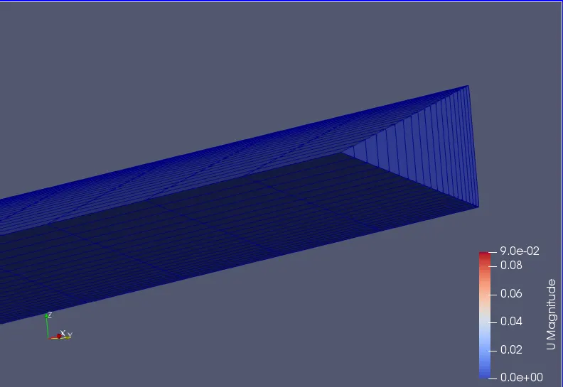
fig(x)
fig(w) and fig(x) shows the mesh structure of wedge for a pipe.
Change in velocity :
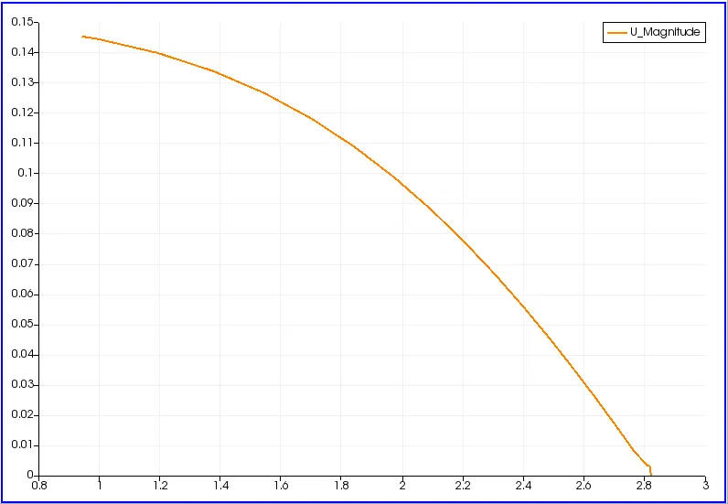
fig(y)
The above plot shows the change in velocity with respect to time step for the given length of the pipe which is for x=2.82m
Change in pressure :
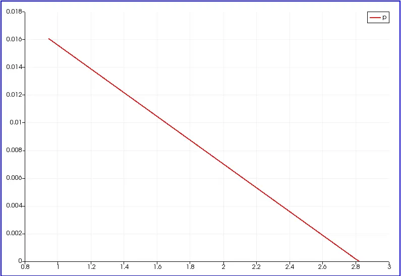
fig(z)
The above plot shows the change in pressure with respect to time step for the given length of the pipe which is for x=2.82m.
Change in shear stress :
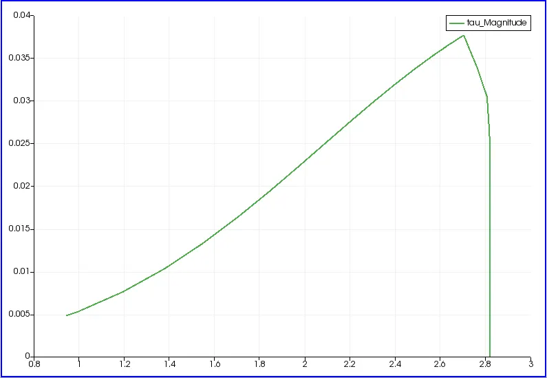
fig(1)
The above plot shows the change in shear stress with respect to time step for the given length of the pipe which is for x=2.82.
For symmetry boundary condition :
For wedge angle 10 degree :
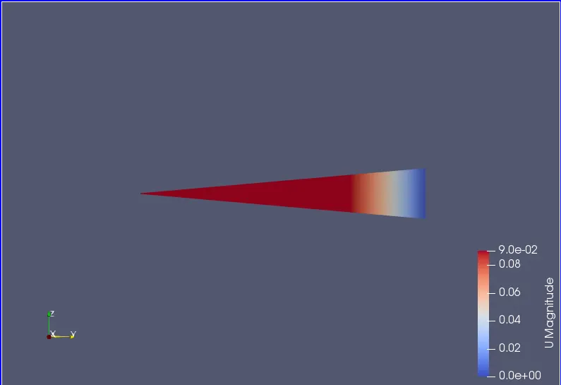
fig(2)
fig(2) shows the simulation of change in velocity with respect to the time step for the given length of pipe.
Change in pressure :
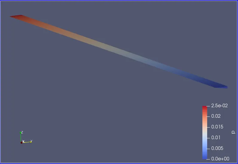
fig(3)
fig(3) shows the simulation of change in pressure with respect to the time step for the given length of pipe.
Mesh structure :
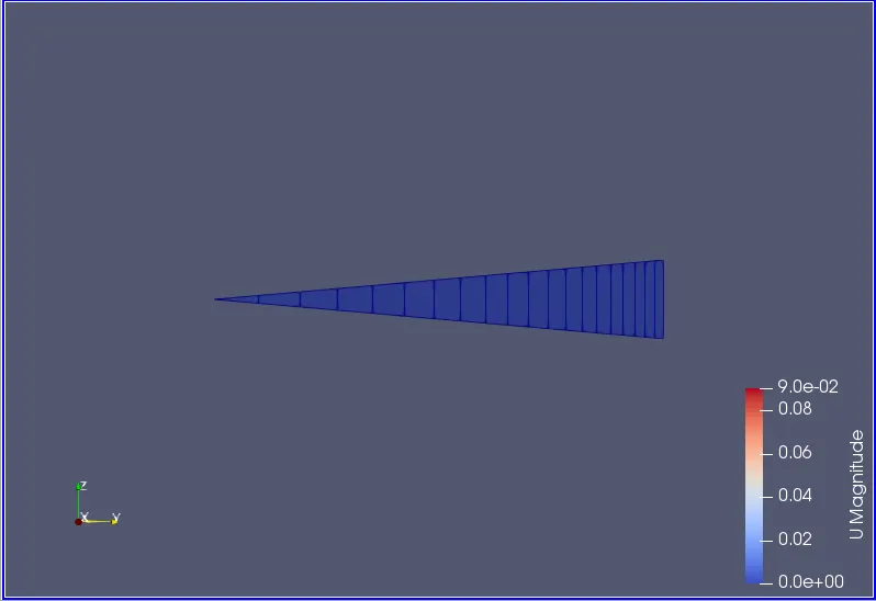
fig(4)
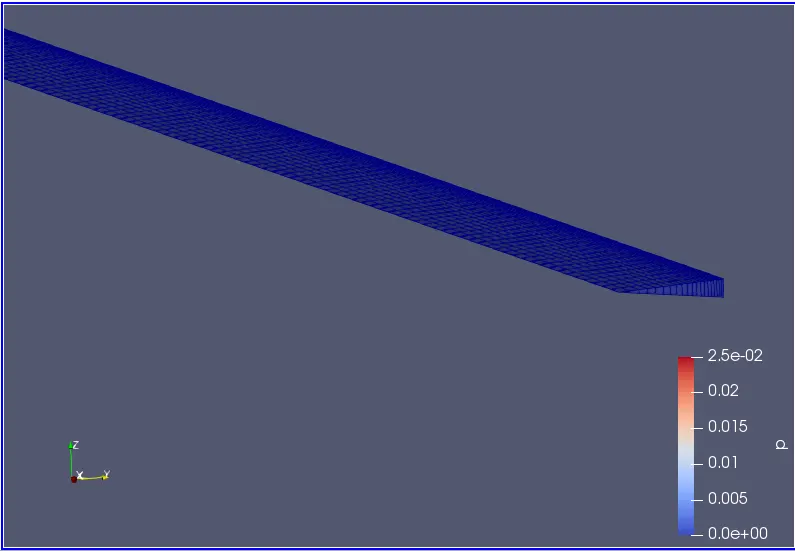
fig(5)
fig(4) and fig(5) shows the mesh structure of wedge for a pipe.
Change in velocity :
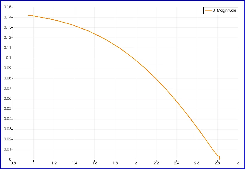
fig(6)
The above plot shows the change in velocity with respect to time step for the given length of the pipe which is for x=2.82m
Change in pressure :
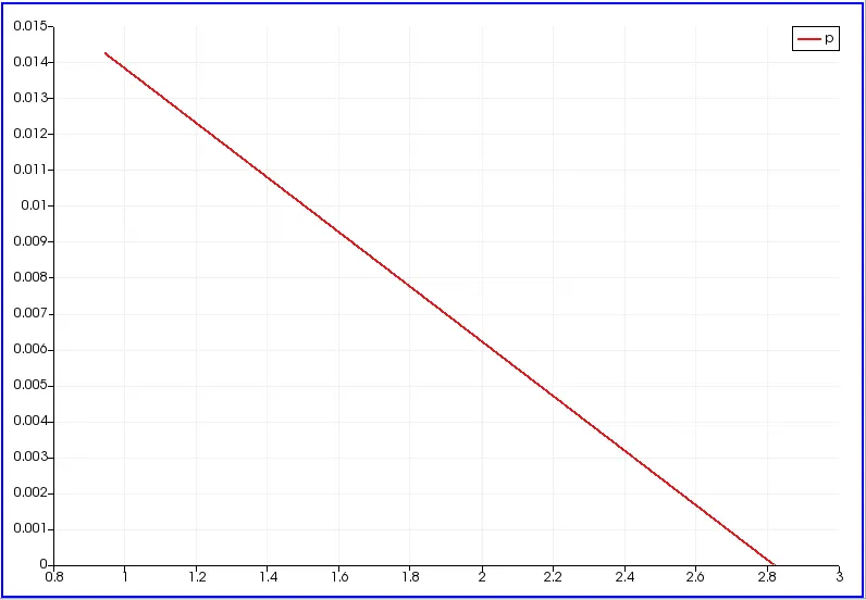
fig(7)
The above plot shows the change in pressure with respect to time step for the given length of the pipe which is for x=2.82m.
Change in shear stress :
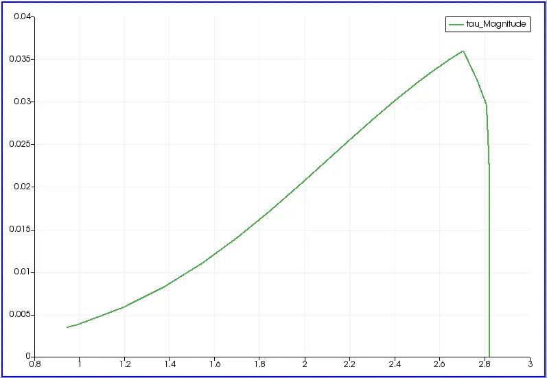
fig(8)
The above plot shows the change in shear stress with respect to time step for the given length of the pipe which is for x=2.82.
For wedge angle 25 degree :
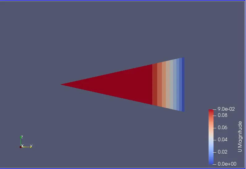
fig(9)
fig(9) shows the simulation of change in velocity with respect to the time step for the given length of pipe.
Change in pressure :
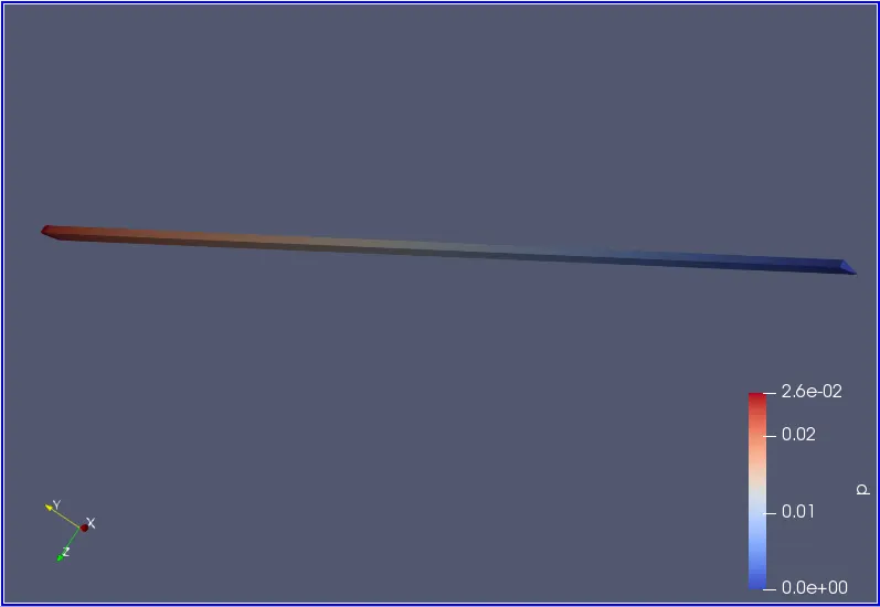
fig(10)
fig(10) shows the simulation of change in pressure with respect to the time step for the given length of pipe.
Mesh structure :
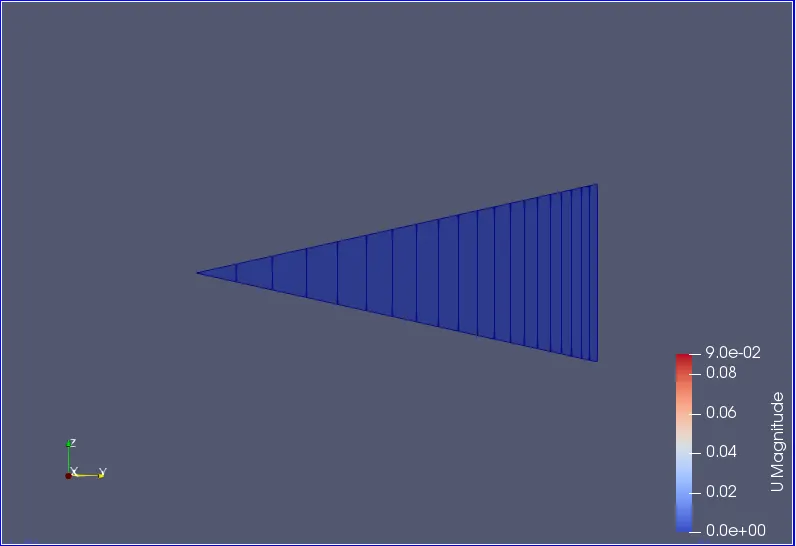
fig(11)
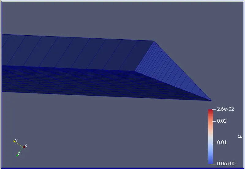
fig(12)
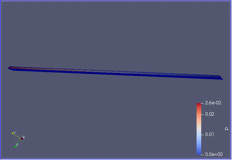
fig(13)
fig(11), fig(12) and fig(13) shows the mesh structure of wedge for a pipe.
Change in velocity :
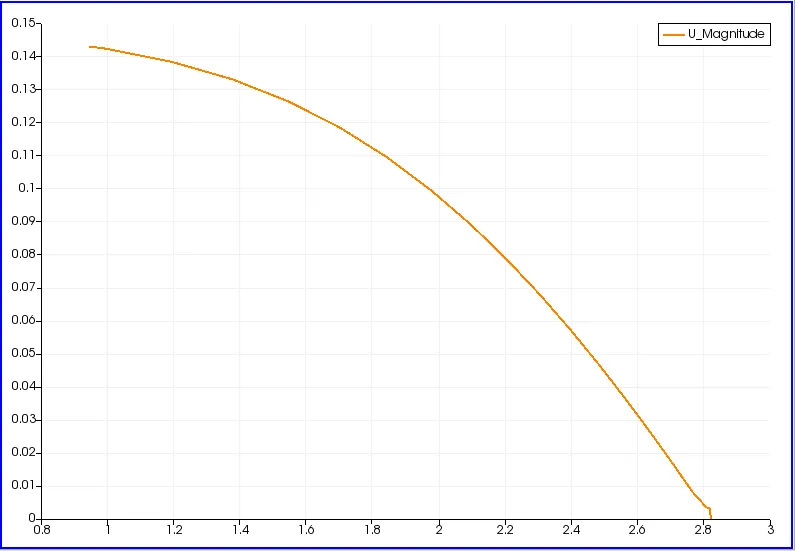
fig(14)
The above plot shows the change in velocity with respect to time step for the given length of the pipe which is for x=2.82m
Change in pressure :
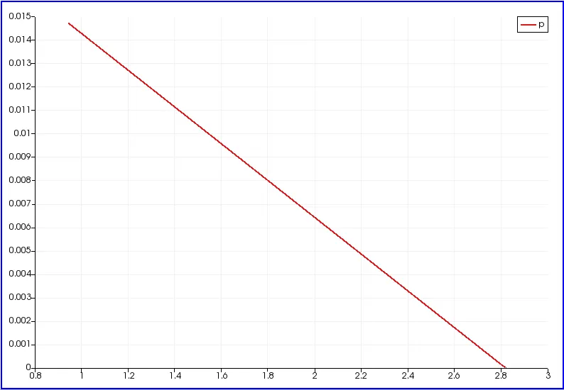
fig(15)
The above plot shows the change in pressure with respect to time step for the given length of the pipe which is for x=2.82m.
Change in shear stress :
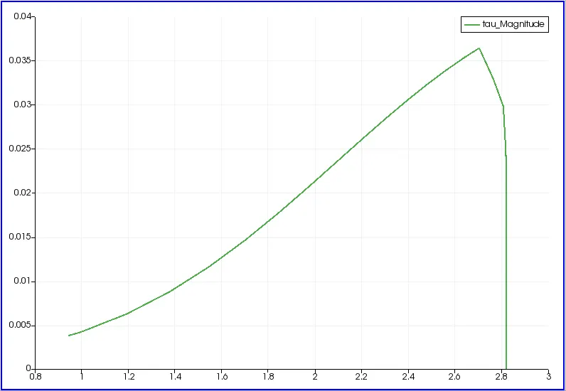
fig(16)
The above plot shows the change in shear stress with respect to time step for the given length of the pipe which is for x=2.82.
For wedge angle 45 degree :
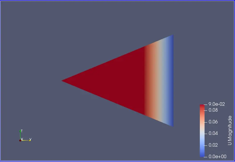
fig(17)
fig(17) shows the simulation of change in velocity with respect to the time step for the given length of pipe.
Change in pressure :
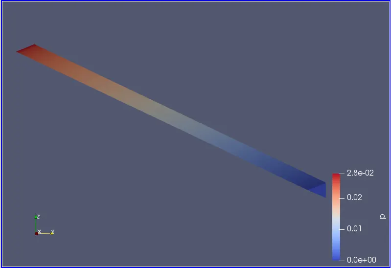
fig(18)
fig(18) shows the simulation of change in pressure with respect to the time step for the given length of pipe.
Mesh structure :
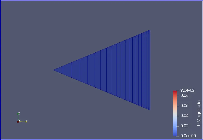
fig(19)
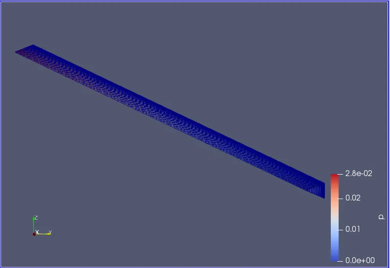
fig(20)
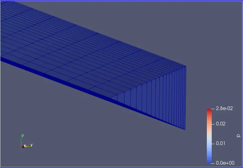
fig(21)
fig(19), fig(20) and fig(21) shows the mesh structure of wedge for a pipe.
Change in velocity :
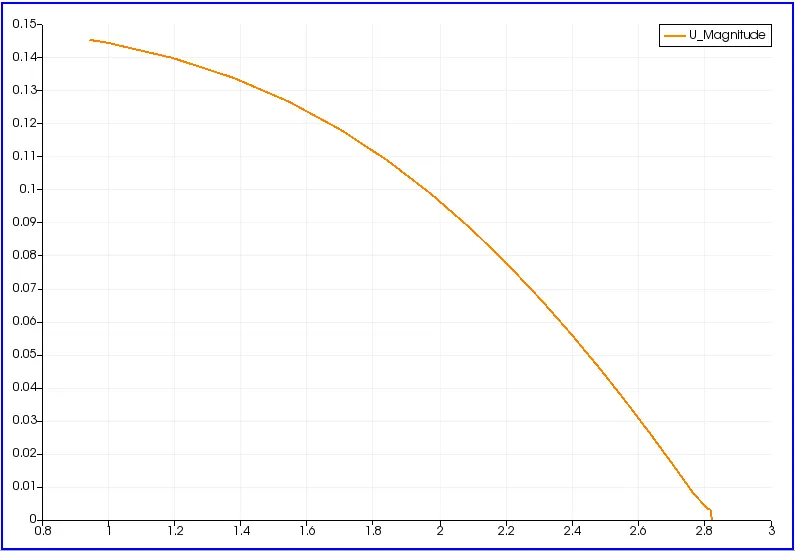
fig(22)
The above plot shows the change in velocity with respect to time step for the given length of the pipe which is for x=2.82m
Change in pressure :
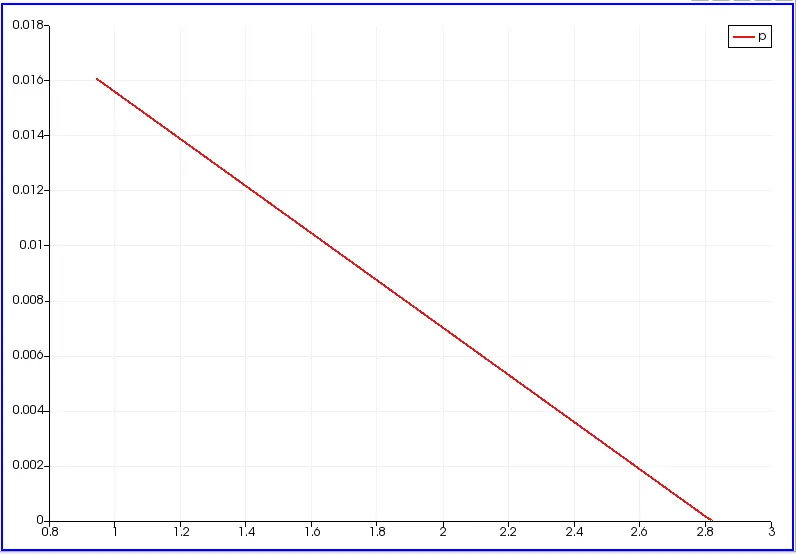
fig(23)
The above plot shows the change in pressure with respect to time step for the given length of the pipe which is for x=2.82m.
Change in shear stress :
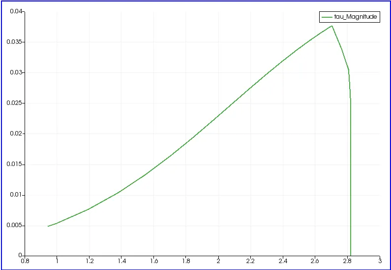
fig(24)
The above plot shows the change in shear stress with respect to time step for the given length of the pipe which is for x=2.82.
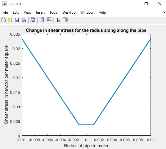
fig(25)
The above figure fig(i) shows that the change in shear stress along the radius of a pipe which is calculated analytically.
Analytically calculated value of shear stress = 0.0334 `N/m^2`
In numerically calculated value of shear stress, The error is minimum when the wedge angle is low and error keeps on increasing when the wedge angle increases. So from this when can say that lower the wedge angle the error will be minimum. Further that error can be reduced by reducing the grid size or by increasing the number of mesh which will leads to increase in number of steps and computational time.
Conclusion :
- The simulate of an axi-symmetric flow by applying the wedge boundary and symmetry boundary condition is successfully compiled and ran successfully, the results are discussed at the output.
- The symmetry boundary condition defines a mirror face/surface. It should only be used if the physical object or geometry and the expected flow field pattern of the developed solution are mirrored along that surface. The fluxes across the symmetry are zero.
- But in wedge boundary it is employed in the situation where the model and flow must be axisymmetric along a central line such that all physical variables of the flow have the same value and distribution at a given radius for all angles One big advantage of wedge is that it allows for the rotational flow around the axis and this is possible only because the fluxes and normal components are not assumed as zero.
- In the point of view of wedge angles it should be kept minimum in order to get an accurate results.