Week 12 - Symmetry vs Wedge vs HP equation
Introduction
The wedge boundary condition for OpenFoam is suitable for the angle less than 5 degree and only supports for the 2D axi-symmetric cases, whereas the symmetric boundary condition are can be used for 2D and 3D geometry.
In the challenge we have to compare the wedge boundary condition with symmetric boundary conditions with different angle. The code or file for the simulation will be the same only the for symmetric boundary conditions instead of wedge we will use symmetry for the front and back faces.
Problem Statements
- Create the parsing file for blockMeshDict file using symmetry boundary condition.
- Simulate the Hagen-Poisuelle equation for different angles usign symmetry boundary conditions.
- Compare the results of wedge angles determined in challenge 10 with the symmetry boundary conditions results.
- Give observations on the results.
a)
The input for the equation will be the same for challenge 11 which are given as:
- Density of Water = 997 kg/m3.
- Dynamic Viscosity = 8.9e-4 Pa.s
- Reynolds Number = 1400
- Diameter of pipe = 0.025 m
- Inlet velocity = 0.18 m/s
Outputs calculation from Hagen-Poisuelle equations:
- Average velocity = Vavg= 0.1869 ms^-1
- Maximum velocity = Vmax=2.Vavg = 0.3738 ms^-1
- Pressure drop = ΔP= 79.84 Pa
- Kinematic Pressure = ΔPk= 0.1 Kgm^2s^-2
- Total Length of Pipe = 2.5 Meters
% MATLAB code for Parsing file for Symmetry BC is given as:

clear all
close all
clc

%Considering Reynold's Number for Simulation
re = 1400;
% Consideration Diameter of Pipe from the equation
D = 0.025;
%Radius of pipe
r = D/2;
%Total length of Pipe is given as
L_t = 2.5;
%Considering angle of wedge (more than 5 deg)
theta = 10;
% Considering dynamic viscosity
mu = 0.89e-3;
% Density of fluid (kg/m3)
Rho = 997;

% Deriving variable from Hagen poiseuille equation
v_avg = (re*mu)/(Rho*D);        % Average Velocity
v_max = 2*(v_avg);              % Maximum Velocity
Del_p = (8*mu*L_t*v_avg)/(r^2); % Pressure difference
k_p = Del_p/Rho;                % Kinematic Pressure

% Calculating Shear stress
R = linspace(0,r,1000);

for i = 1:length(R)
    tau(i) = 2*mu*v_max*(abs(R(i)))/r^2;
end

plot(R,tau)
xlabel('Radius')
ylabel('Shear Stress')
grid on
legend ('Shear stress in Pipe')
% Printing the file

header1='/*--------------------------------*- C++ -*----------------------------------*';
header2='  =========                 |                                                  ';
header3='  \      /  F ield         | OpenFOAM: The Open Source CFD Toolbox            ';
header4='   \    /   O peration     | Website:  https://openfoam.org                   ';
header5='    \  /    A nd           | Version:  8                                      ';
header6='     \/     M anipulation  |                                                  ';
header7='*---------------------------------------------------------------------------*/';

f1 = fopen('blockMeshDict','w');
fprintf(f1, '%sn', header1);
fprintf(f1, '%sn', header2);
fprintf(f1, '%sn', header3);
fprintf(f1, '%sn', header4);
fprintf(f1, '%sn', header5);
fprintf(f1, '%sn', header6);
fprintf(f1, '%sn', header7);

fprintf(f1, 'FoamFilen{n');
fprintf(f1, '%12s t 2.0;n', 'version');
fprintf(f1, '%12s t ascii;n','format');
fprintf(f1, '%12s t dictionary;n','class');
fprintf(f1, '%12s t blockMeshDict;n','object');
fprintf(f1, '}n');
header8='// * * * * * * * * * * * * * * * * * * * * * * * * * * * * * * * * * * * * * //';
fprintf(f1, '%snn',header8);

fprintf(f1, 'convertToMeters 1;nn');

fprintf(f1, 'verticesn');
fprintf(f1, '(n');
fprintf(f1, 't (%d  %d %d)n',0,0,0);
fprintf(f1, 't (%d  %d %d)n',r*sind(theta/2),r*cosd(theta/2),0);
fprintf(f1, 't (%d  %d %d)n',-r*sind(theta/2),r*cosd(theta/2),0);
fprintf(f1, 't (%d  %d %d)n',0,0,L_t);
fprintf(f1, 't (%d  %d %d)n',r*sind(theta/2),r*cosd(theta/2),L_t);
fprintf(f1, 't (%d  %d %d)n',-r*sind(theta/2),r*cosd(theta/2),L_t);
fprintf(f1, ');nn');


fprintf(f1, 'blocksn');
fprintf(f1, '(n');
fprintf(f1, 't hex (0 0 1 2 3 3 4 5) (%d %d %d)',1,50,300);
fprintf(f1, ' SimpleGrading (1 0.5 1)nn');
fprintf(f1, ');nn');

fprintf(f1, 'edgesn');
fprintf(f1, '(n');
fprintf(f1, 't arc %d %d (%d %d %d)n',1,2,0,r,0);
fprintf(f1, 't arc %d %d (%d %d %d)n',4,5,0,r,L_t);
fprintf(f1, ');nn');

fprintf(f1, 'boundaryn');
fprintf(f1, '(n');
fprintf(f1, 't inletn');
fprintf(f1, 't {n');
fprintf(f1, 'tt type patch;n');
fprintf(f1, 'tt facesn');
fprintf(f1, 'tt (n');
fprintf(f1, 'ttt (0 0 2 1)n');
fprintf(f1, 'tt );n');
fprintf(f1, 't }n');


fprintf(f1, 't outletn');
fprintf(f1, 't {n');
fprintf(f1, 'tt type patch;n');
fprintf(f1, 'tt facesn');
fprintf(f1, 'tt (n');
fprintf(f1, 'ttt (3 4 5 3)n');
fprintf(f1, 'tt );n');
fprintf(f1, 't }n');

fprintf(f1, 't topn');
fprintf(f1, 't {n');
fprintf(f1, 'tt type wall;n');
fprintf(f1, 'tt facesn');
fprintf(f1, 'tt (n');
fprintf(f1, 'ttt (4 1 2 5)n');
fprintf(f1, 'tt );n');
fprintf(f1, 't }n');


fprintf(f1, 't frontn');
fprintf(f1, 't {n');
fprintf(f1, 'tt type symmetry;n');
fprintf(f1, 'tt facesn');
fprintf(f1, 'tt (n');
fprintf(f1, 'ttt (0 1 4 3)n');
fprintf(f1, 'tt );n');
fprintf(f1, 't }n');


fprintf(f1, 't backn');
fprintf(f1, 't {n');
fprintf(f1, 'tt type symmetry;n');
fprintf(f1, 'tt facesn');
fprintf(f1, 'tt (n');
fprintf(f1, 'ttt (3 5 2 0)n');
fprintf(f1, 'tt );n');
fprintf(f1, 't }n');

fprintf(f1, 't axisn');
fprintf(f1, 't {n');
fprintf(f1, 'tt type empty;n');
fprintf(f1, 'tt facesn');
fprintf(f1, 'tt (n');
fprintf(f1, 'ttt (0 3 3 0)n');
fprintf(f1, 'tt );n');
fprintf(f1, 't }n');
fprintf(f1, '); nn');

fprintf(f1, 'mergePatchPairsn');
fprintf(f1, '(n');
fprintf(f1, ');n');

header9='// ************************************************************************* //';
fprintf(f1, '%sn',header9);

fclose(f1);
The generated block mesh dict file for 10 degree of wedge with symmetry boundary condition can be seen below:
/*-----------------------------*- C++ -*----------------------------*
  =========                |
  \      /  F ield        | OPENFOAM: The Open Source CFD Toolbox
   \    /   O peration    | Version: 7
    \  /    A nd          | Web:   www.OpenFOAM.ORG
     \/     M anipulation |
*------------------------------------------------------------------*/
 FoamFile
{
     version      2.0;
     format       ascii;
     class        dictionary;
     object       blockMeshDict;
}
// * * * * * * * * * * * * * * * * * * * * * * * * * * * * * * * * //

convertToMeters 1;
vertices
(
      (0.000000 0.000000 0.000000)
      (0.000000 0.009962 -0.000872)
      (0.000000 0.009962 0.000872)
      (2.520000 0.000000 0.000000)
      (2.520000 0.009962 -0.000872)
      (2.520000 0.009962 0.000872)
);

blocks
(
      hex (0 1 2 0 3 4 5 3) (50 1 200) simpleGrading (0.5 1 1)
);

edges
(
      arc 1 2 (0.000000 0.010000 0.000000)
      arc 4 5 (2.520000 0.010000 0.000000)
);

boundary
(
      inlet
      {
           type patch;
           faces
           (
                (0 1 2 0)
           );
      }
      outlet
      {
           type patch;
           faces
           (
                (3 4 5 3)
           );
      }
      front
      {
           type symmetry;
           faces
           (
                (0 3 5 2)
           );
      }
      back
      {
           type symmetry;
           faces
           (
                (0 1 4 3)
           );
      }
      pipe
      {
           type wall;
           faces
           (
                (1 4 5 2)
           );
      }
      axis
      {
           type empty;
           faces
           (
                (0 3 3 0)
           );
      }
);

mergePatchPairs
(
);

//*****************************************************************//
The generated block mesh dict file for the 25 degree wedge can be seen below:
/*-----------------------------*- C++ -*----------------------------*
  =========                |
  \      /  F ield        | OPENFOAM: The Open Source CFD Toolbox
   \    /   O peration    | Version: 7
    \  /    A nd          | Web:   www.OpenFOAM.ORG
     \/     M anipulation |
*------------------------------------------------------------------*/
 FoamFile
{
     version      2.0;
     format       ascii;
     class        dictionary;
     object       blockMeshDict;
}
// * * * * * * * * * * * * * * * * * * * * * * * * * * * * * * * * //

convertToMeters 1;
vertices
(
      (0.000000 0.000000 0.000000)
      (0.000000 0.009763 -0.002164)
      (0.000000 0.009763 0.002164)
      (2.520000 0.000000 0.000000)
      (2.520000 0.009763 -0.002164)
      (2.520000 0.009763 0.002164)
);

blocks
(
      hex (0 1 2 0 3 4 5 3) (50 1 200) simpleGrading (0.5 1 1)
);

edges
(
      arc 1 2 (0.000000 0.010000 0.000000)
      arc 4 5 (2.520000 0.010000 0.000000)
);

boundary
(
      inlet
      {
           type patch;
           faces
           (
                (0 1 2 0)
           );
      }
      outlet
      {
           type patch;
           faces
           (
                (3 4 5 3)
           );
      }
      front
      {
           type symmetry;
           faces
           (
                (0 3 5 2)
           );
      }
      back
      {
           type symmetry;
           faces
           (
                (0 1 4 3)
           );
      }
      pipe
      {
           type wall;
           faces
           (
                (1 4 5 2)
           );
      }
      axis
      {
           type empty;
           faces
           (
                (0 3 3 0)
           );
      }
);

mergePatchPairs
(
);

//*****************************************************************//
The generated block mesh dict file for 45 degree of wedge with symmetry boundary condition can be seen below:
/*-----------------------------*- C++ -*----------------------------*
  =========                |
  \      /  F ield        | OPENFOAM: The Open Source CFD Toolbox
   \    /   O peration    | Version: 7
    \  /    A nd          | Web:   www.OpenFOAM.ORG
     \/     M anipulation |
*------------------------------------------------------------------*/
 FoamFile
{
     version      2.0;
     format       ascii;
     class        dictionary;
     object       blockMeshDict;
}
// * * * * * * * * * * * * * * * * * * * * * * * * * * * * * * * * //

convertToMeters 1;
vertices
(
      (0.000000 0.000000 0.000000)
      (0.000000 0.009239 -0.003827)
      (0.000000 0.009239 0.003827)
      (2.520000 0.000000 0.000000)
      (2.520000 0.009239 -0.003827)
      (2.520000 0.009239 0.003827)
);

blocks
(
      hex (0 1 2 0 3 4 5 3) (50 1 200) simpleGrading (0.5 1 1)
);

edges
(
      arc 1 2 (0.000000 0.010000 0.000000)
      arc 4 5 (2.520000 0.010000 0.000000)
);

boundary
(
      inlet
      {
           type patch;
           faces
           (
                (0 1 2 0)
           );
      }
      outlet
      {
           type patch;
           faces
           (
                (3 4 5 3)
           );
      }
      front
      {
           type symmetry;
           faces
           (
                (0 3 5 2)
           );
      }
      back
      {
           type symmetry;
           faces
           (
                (0 1 4 3)
           );
      }
      pipe
      {
           type wall;
           faces
           (
                (1 4 5 2)
           );
      }
      axis
      {
           type empty;
           faces
           (
                (0 3 3 0)
           );
      }
);

mergePatchPairs
(
);

//*****************************************************************//
The Boundary condition were then put as per the analytical solution found. The velocity file can be seen below:
/*--------------------------------*- C++ -*----------------------------------*
  =========                 |
  \      /  F ield         | OpenFOAM: The Open Source CFD Toolbox
   \    /   O peration     | Website:  https://openfoam.org
    \  /    A nd           | Version:  6
     \/     M anipulation  |
*---------------------------------------------------------------------------*/
FoamFile
{
    version     2.0;
    format      ascii;
    class       volVectorField;
    object      U;
}
// * * * * * * * * * * * * * * * * * * * * * * * * * * * * * * * * * * * * * //

dimensions      [0 1 -1 0 0 0 0];

internalField   uniform (0 0 0);

boundaryField
{
    inlet
    {
        type            fixedValue;
        value           uniform (0.0937312 0 0);
    }

    outlet
    {
        type            zeroGradient;
    }

    pipe
    {
        type            noSlip;
    }

    axis
    {
        type            empty;
    }

    front
    {
        type            symmetry;
    }

    back
    {
        type            symmetry;
    }
}

// ************************************************************************* //
The pressure File can be seen below:
/*--------------------------------*- C++ -*----------------------------------*
  =========                 |
  \      /  F ield         | OpenFOAM: The Open Source CFD Toolbox
   \    /   O peration     | Website:  https://openfoam.org
    \  /    A nd           | Version:  6
     \/     M anipulation  |
*---------------------------------------------------------------------------*/
FoamFile
{
    version     2.0;
    format      ascii;
    class       volScalarField;
    object      p;
}
// * * * * * * * * * * * * * * * * * * * * * * * * * * * * * * * * * * * * * //

dimensions      [0 2 -2 0 0 0 0];

internalField   uniform 0;

boundaryField
{
    axis
    {
        type            empty;
    }

    pipe
    {
        type            zeroGradient;
    }

    inlet
    {
        type            zeroGradient;
    }

    outlet
    {
        type            fixedValue;
        value           uniform 0.0168682;
    }

    front
    {
        type            symmetry;
    }

    back
    {
        type            symmetry;
    }
}

// ************************************************************************* //
Control dict file 10 deg and 25 deg
/*--------------------------------*- C++ -*----------------------------------*
  =========                 |
  \      /  F ield         | OpenFOAM: The Open Source CFD Toolbox
   \    /   O peration     | Website:  https://openfoam.org
    \  /    A nd           | Version:  6
     \/     M anipulation  |
*---------------------------------------------------------------------------*/
FoamFile
{
    version     2.0;
    format      ascii;
    class       dictionary;
    location    "system";
    object      controlDict;
}
// * * * * * * * * * * * * * * * * * * * * * * * * * * * * * * * * * * * * * //

application     icoFoam;

startFrom       startTime;

startTime       0;

stopAt          endTime;

endTime         10;

deltaT          0.001;

writeControl    timeStep;

writeInterval   20;

purgeWrite      0;

writeFormat     ascii;

writePrecision  6;

writeCompression off;

timeFormat      general;

timePrecision   6;

runTimeModifiable true;


// ************************************************************************* //
For wedge of 45 degree the Control dict file
/*--------------------------------*- C++ -*----------------------------------*
  =========                 |
  \      /  F ield         | OpenFOAM: The Open Source CFD Toolbox
   \    /   O peration     | Website:  https://openfoam.org
    \  /    A nd           | Version:  6
     \/     M anipulation  |
*---------------------------------------------------------------------------*/
FoamFile
{
    version     2.0;
    format      ascii;
    class       dictionary;
    location    "system";
    object      controlDict;
}
// * * * * * * * * * * * * * * * * * * * * * * * * * * * * * * * * * * * * * //

application     icoFoam;

startFrom       startTime;

startTime       0;

stopAt          endTime;

endTime         10;

deltaT          0.0005;

writeControl    timeStep;

writeInterval   20;

purgeWrite      0;

writeFormat     ascii;

writePrecision  6;

writeCompression off;

timeFormat      general;

timePrecision   6;

runTimeModifiable true;


// ************************************************************************* //
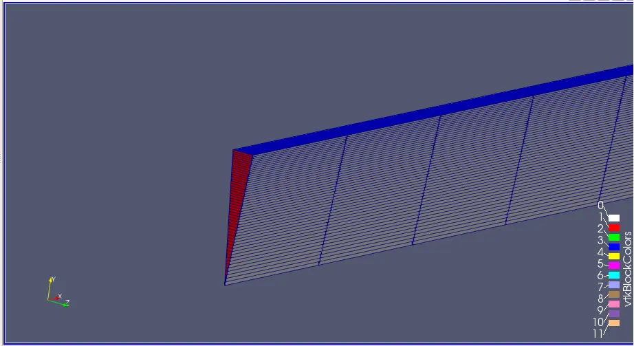
The axi symmetric mesh was generated and can be seen in the figure below for 10degree wedge:
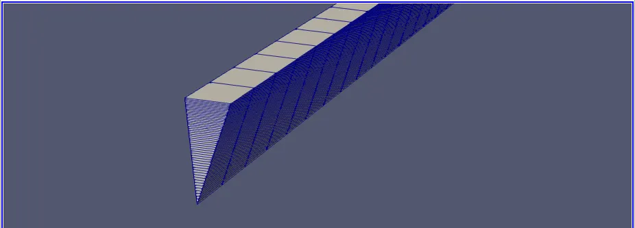
The axi symmetric mesh was generated and can be seen in the figure below for 25 degree wedge:
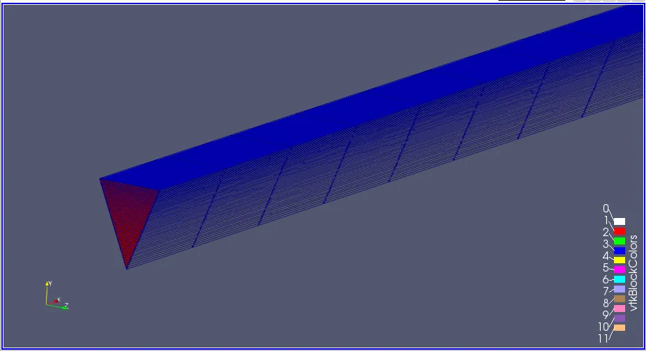
The axi symmetric mesh was generated and can be seen in the figure below for 45 degree wedge:
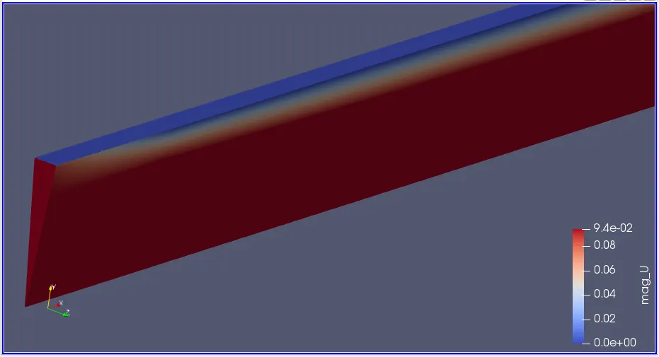
After running the simulation the wedge velocity contour can be seen below
1.)At 10degree
2.) At 25 degree
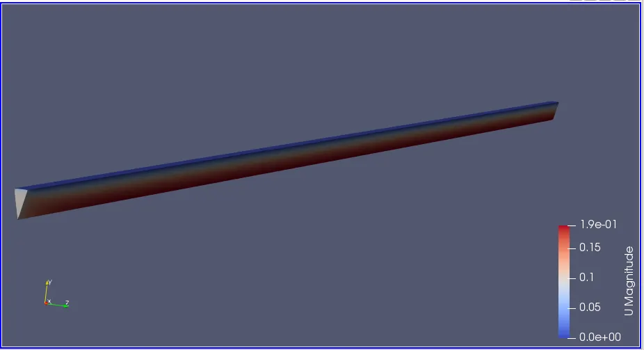
3.)At 45 degree
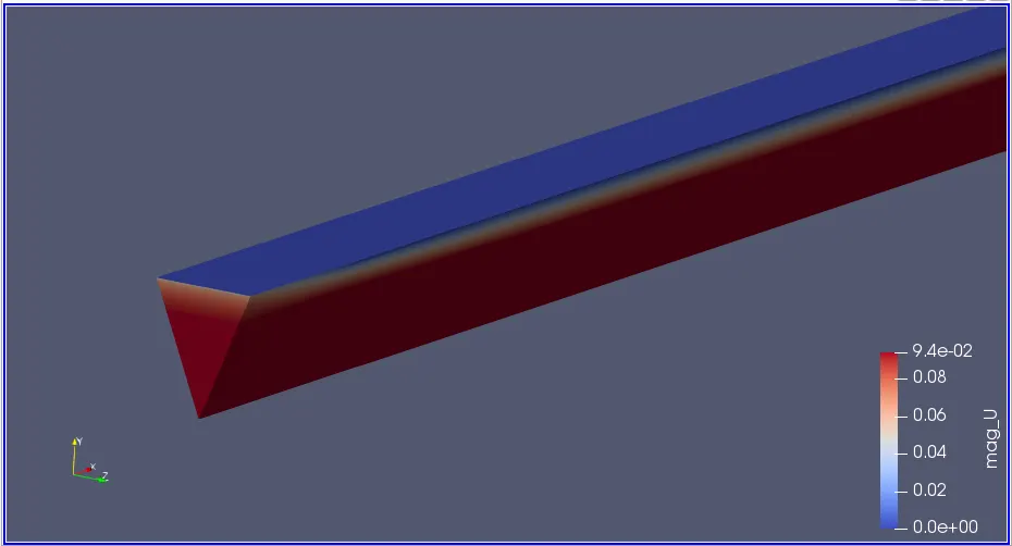
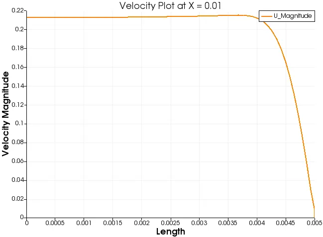
For the pipe of wedge angle 10 degree
A) Velocity Contour
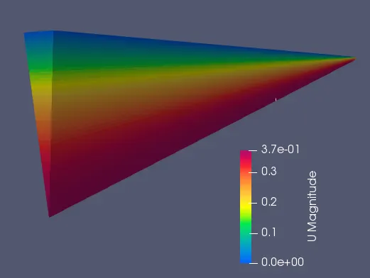
B) Plot of Velocity at X = 0.01
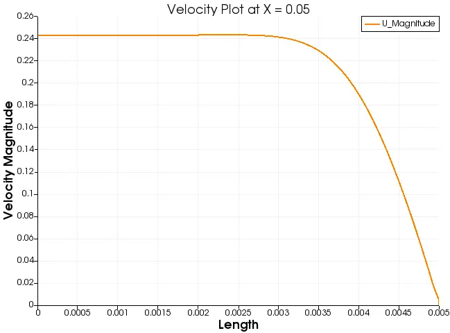
C) Plot of Velocity at X = 0.05
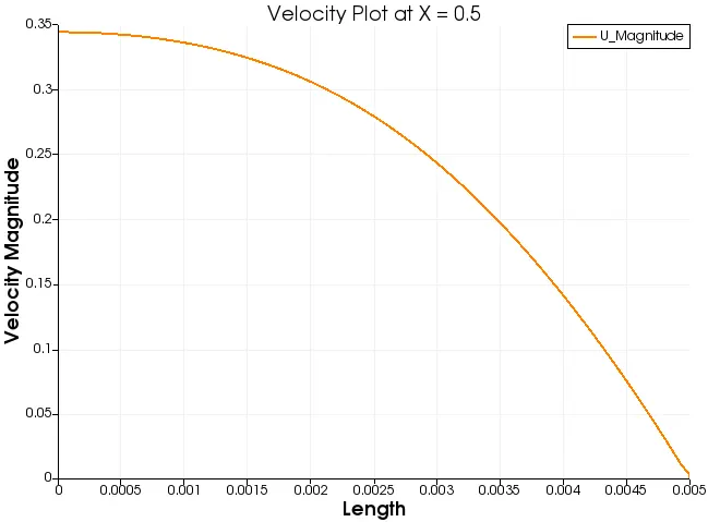
D) Plot of Velocity at X = 0.5
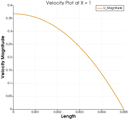
E) Plot of Velocity at X = 1
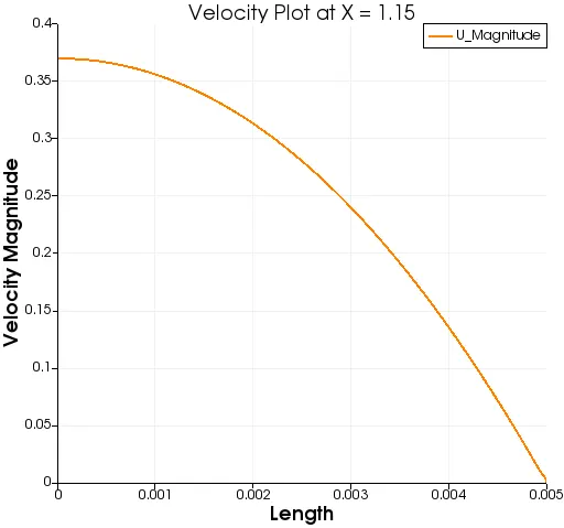
F) Plot of Velocity at X = 1.15
Result Comparision and Disscussions:
| Wedge Angle | Max. Velocity (HP Equation) | Max. Velocity Simulation | Max. Shear Stress |
| 4Degree (Wedge BC) | 0.3738 | 0.375 | 0.045 |
| 10Degree(Symmetry BC) | 0.3738 | 0.370309 | 0.034 |
| 25Degree(Symmetry BC) | 0.3738 | 0.370765 | 0.035 |
| 45Degree(Symmetry BC) | 0.3738 | 0.371764 | 0.036 |
- With increase in the wedge angle => velocity tends to the exact solution or the accurate solution.
- Symmetry BC is quiet better than that of wedge BC as it gives more accurate results
- Symmetry BC takes more computational time as compared to wedge BC.
- At 0.001, for all the cases the velocity is stable at the centre this shows the flow is still developing and the developing flow can be seen in this ares.
- It can be seen that at around 0.15m from the inlet, for all the cases the velocity profile becomes fully developed thus indicationg the fully developed region.
- The velocity dipped to zero at the edge near the pipe walls for all the cases this testifies the no-slip BC.
- The shear stress also testified the full HP equations i.e. stress maximum at the walls and dipping to zero at the centre, thus maximum velocity at the centre.
- As the wedge angle increases => courant number also increases. This can be explained as the increase in the element size of the mesh as the number of elements remain same in the analysis. Thus, courant number is directly propotional to the element size.