Week 11 - Simulation of Flow through a pipe in OpenFoam
Objective of the Project:
- To run simulation of internal flow through a pipe.
- To calculate hydrodynamic entry length, total length of pipe.
- To plot velocity profile across the pipe at different locations along the direction of flow.
- To plot shear stress.
Introduction:
We consider flow of fluids in the form of layers, when fluid flows through a pipe the layers which are in contact with the walls of the pipe comes to complete rest and hence velocity of those layers becomes zero and this is called as no slip condition. So starting from the wall if we move in radial direction to the centre of pipe velocity of layers keeps on increasing, at the centre the velocity of the layer is free stream velocity. This can be illustrated as follow,
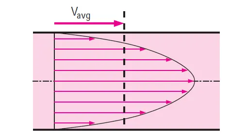
It can be seen that the velocity profile across the pipe is parabolic.
As stated in the above paragraph, as we move from the surface of the wall to the centre of the pipe velocity increase, i.e if we consider a fluid layer velcoity of that particular layer will either relativley more than the layer above it and also relativley less than the layer below it. i.e, there is a relative velocity difference between the layers. So in this case the layer with lower velocity drags the layer with higher velocity in a direction opposite to the direction of flow and hence tries to slow down the layer with higher velocity, this results in developing a shear stress between the layers.
Since the layer which is in contact with the wall has zero velocity (No slip condition), shear stress at that particular layer will be highest. As we move to the centre of the pipe the shear stress decreases. It will be lowest at the centre of pipe where the velocity is free stream velocity.
A hypothetical boundary is considered from the entry of fluid into the pipe, it has a thickness which keeps on increasing from the entry to where the velocity reaches 99% of free stream velocity, this hypothetical layer is called as boundary layer. It can be illustrated as follow,
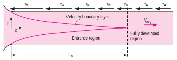
As illsutrated above the velocity profile across the pipe is parabolic, but this paraboic profile is that of a fully developed flow, meaning when fluid starts flowing through the pipe the velocity profile wont to completley parabolic, after a particular distance along the flow direction we can say that the flow is completley developed so this distance strating from the entry of the pipe to a point where the flow is completley developed is a called as Hydrodynamic entry length. From the entry until this distance the velocity profile is not completley parabolic, or in other words the profile is developing. It can be illustrated as follow,
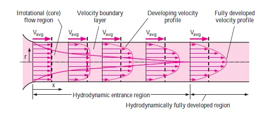
Hydrodynamic entry length's are calculated using a formula, the formula to be used to calculate hydrodynamic entry length varies for a laminar flow as well as for turbulent flow.
For laminar flow, Hydrodynamic entry length, Lh=0.05⋅Re⋅D
where, Lh - is hydrodynamic entry length (m)
Re - is Reynolds number
D - is Characteristic length (m), (For internal flow through a pipe characteristic length is nothing but diameter of the pipe)
For turbulent flow, Hydrodynamic entry length, Lh=1.359⋅D⋅(Re)14
where, Lh - is hydrodynamic entry length (m)
Re - is Reynolds number
D - is Characteristic length (m), (For internal flow through a pipe characteristic length is nothing but diameter of the pipe)
=> for viscous flow the shear stress is related to the velocity gradient as, τ=μ⋅∂u∂y
which is also known as newton's law of viscocity
It is essential to understand the above stated flow physics before we dive into setting up the simulations.
# Simulations:
# Setting up the simulation:
Simulation is done using Openfoam. Since it is flow through a cylindrical pipe rather than considering a complete pipe, a small sector with an angle of sweep less than 5 degree is considered and this particular sector is meshed and boundary conditions are applied and then icoFoam solver is used to run the simulation.
# Creating the geometry:
In openFoam creating a geometry means editing the blockMeshDict file to create the required geometry. This blockMeshDict file is created in matlab using file parsing.
Flow of water at 25 °C entering the a pipe of diameter 0.025 m at a velocity of 0.05 m/s is considered for the simulation. Since we have flow condition, very next thing would be to calculate the Reynolds number and determine wether the flow is lamninar or turbulent,
Re=U⋅Dν
Where , Re - Reynolds number
U - Inlet velocity (m/s)
D - characteristic length (m)
ν - Kinematic viscosity of water at 25 °C (m^2/s)
at 25 °C kinematic visosity of water, ν=0.893⋅10-6m2s
Therefore, Re = (0.05*0.025)/0.893*10^-6 = 1399.77 ≈1400.
For internal flow Re number more than 2300 is considered as turbulent flow. In our calculations we have Re < 2300 and hence the flow is laminar.
We have for laminar flow, Hydrodynamic entry length, Lh=0.05⋅Re⋅D
Therefore, Lh=0.05⋅1400⋅0.025=1.75
i.e, from the inlet till a length of 1.75 meters the flow is not completley developed, so a 0.75 m extra length is provided so that it is possible to plot velocity profile of completley developed flow. Therefore the total length of pipe is taken as 1.75 + 0.75 = 2.5 m
* Sector which is to be created using blockMeshDict file, has a sweep angle less than 5° since the angle is small the the arc can be approximated to a straight line, it can be illustrated as follow,
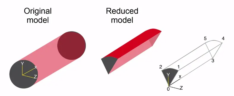
so the co-ordinates for the vertices of the vector is calculated using the trignometric functinons, y=d2⋅cos(θ2) and z=d2⋅sin(θ2)it can be illustrated in a simple way as follow,
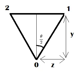
In this simulation angle of 2° is taken accordingly the blockMeshDict file is created by file parsing in matlab.
Boundaries incuded are - inlet, outlet both which are of type patch
- Front and back which are of type wedge
- No slip wall which is of type wall
- axis which is of type empty
%Automated blockmesh generation using MATLAB :

clear all
close all
clc

% Input Paramaters
Re = 1400; % given value
% assume values
t =  25;
rho = 997;
nu = 8.9e-4;
d = 0.025;
r = d/2;
theta =2; %wedge angle
l = 0.06*d*Re; % entrance length formula for laminar flow
x = l;
y = r*cosd(theta/2);
z = r*sind(theta/2);
v = Re*nu/(rho*d); % average velocity
v_max = 2*v; % maximum velocity
p = 32*nu*v*l/d^2; % pressure
p_k = p/rho; % pressure value is in terms of kinetic pressure so it is divided by density

t1 = ('/*------------------------------------ *- C++ -*----------------------------------------*\');
t2 = ('  ============                    |');
t3 = ('  \\         /  F ield            | OpenFOAM: The Open Source CFD Toolbox');
t4 = ('    \\      /   O peration        | Website:  https://openfoam.org');
t5 = ('      \\   /    A nd              | Version:  8');
t6 = ('        \\/     M anipulation     |');

% write a file
f1 = fopen('blockmesh','w+t');
fprintf(f1,'%s \n',t1)
fprintf(f1,'%s\n',t2)
fprintf(f1,'%s \n',t3)
fprintf(f1,'%s \n',t4)
fprintf(f1,'%s \n',t5)
fprintf(f1,'%s \n',t6)
fprintf(f1,'/*--------------------------------------------------------------------------------------*/ \n')
fprintf(f1,' FoamFile \n')
fprintf(f1,' { \n')
fprintf(f1,'    version     2.0; \n')
fprintf(f1,'    format      ascii; \n')
fprintf(f1,'    class       dictionary; \n')
fprintf(f1,'    object      blockMeshDict; \n')
fprintf(f1,' } \n')
fprintf(f1,'// * * * * * * * * * * * * * * * * * * * * * * * * * * * * * * * * * * * * * * * *  * * // \n\n')
fprintf(f1,'convertToMeters 1; \n\n')
fprintf(f1,'vertices \n')
fprintf(f1,'( \n')
fprintf(f1,'(0 0 0) //point 0 \n')
fprintf(f1,'(0 %f %f) //point 1 \n',y,z)
fprintf(f1,'(0 %f %f) //point 2 \n',y,-z)
fprintf(f1,'(%f 0 0) //point 3 \n',x)
fprintf(f1,'(%f %f %f) //point 4 \n',x,y,z)
fprintf(f1,'(%f %f %f) //point 5 \n',x,y,-z)
fprintf(f1,'); \n\n')
fprintf(f1,'blocks \n')
fprintf(f1,'( \n')
fprintf(f1,'hex (0 3 5 2 0 3 4 1) (100 50 100) simplegrading (1 1 1) \n')
fprintf(f1,'); \n\n')
fprintf(f1,'edges \n')
fprintf(f1,'( \n')
fprintf(f1,'   arc 1 2 (0 %f 0)\n',r)
fprintf(f1,'   arc 4 5 (%f %f 0)\n',l,r)
fprintf(f1,'); \n\n')
fprintf(f1,'boundary \n')
fprintf(f1,'( \n  inlet \n ')
fprintf(f1,'      { \n')
fprintf(f1,'\n         type patch; \n')
fprintf(f1,'         faces \n       ( \n')
fprintf(f1,'         (0 1 2 0)\n')
fprintf(f1,'       ); \n')
fprintf(f1,'       }  \n  ')
fprintf(f1,'outlet \n ')
fprintf(f1,'       { \n')
fprintf(f1,'\n          type patch; \n')
fprintf(f1,'          faces \n        ( \n')
fprintf(f1,'          (3 5 4 3)\n')
fprintf(f1,'        ); \n')
fprintf(f1,'        }  \n  ')
fprintf(f1,'front\n ')
fprintf(f1,'       { \n')
fprintf(f1,'\n          type wedge; \n')
fprintf(f1,'          faces \n        ( \n')
fprintf(f1,'          (1 0 3 4)\n')
fprintf(f1,'        ); \n')
fprintf(f1,'        }  \n  ')
fprintf(f1,'back\n ')
fprintf(f1,'       { \n')
fprintf(f1,'\n          type wedge; \n')
fprintf(f1,'          faces \n        ( \n')
fprintf(f1,'          (2 5 3 0)\n')
fprintf(f1,'        ); \n')
fprintf(f1,'        }  \n  ')
fprintf(f1,'top \n ')
fprintf(f1,'       { \n')
fprintf(f1,'\n          type wall; \n')
fprintf(f1,'          faces \n        ( \n')
fprintf(f1,'          (2 1 4 5)\n')
fprintf(f1,'        ); \n')
fprintf(f1,'        }  \n  ')
fprintf(f1,'bottom \n ')
fprintf(f1,'       { \n')
fprintf(f1,'\n          type empty; \n')
fprintf(f1,'          faces \n        ( \n')
fprintf(f1,'          (0 3 3 0)\n')
fprintf(f1,'        ); \n')
fprintf(f1,'        }  \n  ')
fprintf(f1,'); \n')
fprintf(f1,'mergePatchPairs \n')
fprintf(f1,'( \n')
fprintf(f1,'); \n')
fprintf(f1,'// **************************************************************************** //\n')
% close the file
fclose(f1)
blockmesh.txt file
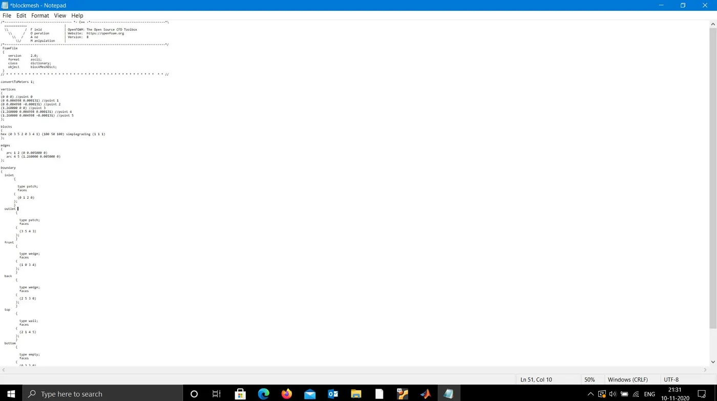
Block Mesh File


/*------------------------------------ *- C++ -*----------------------------------------*\
  ============                    |
  \\         /  F ield            | OpenFOAM: The Open Source CFD Toolbox
    \\      /   O peration        | Website:  https://openfoam.org
      \\   /    A nd              | Version:  8
        \\/     M anipulation     |
/*--------------------------------------------------------------------------------------*/
 FoamFile
 {
    version     2.0;
    format      ascii;
    class       dictionary;
    object      blockMeshDict;
 }
// * * * * * * * * * * * * * * * * * * * * * * * * * * * * * * * * * * * * * * * *  * * //

convertToMeters 1;

vertices
(
(0 0 0) //point 0
(0 0.004619 0.001913) //point 1
(0 0.004619 -0.001913) //point 2
(1.260000 0 0) //point 3
(1.260000 0.004619 0.001913) //point 4
(1.260000 0.004619 -0.001913) //point 5
);

blocks
(
hex (0 3 5 2 0 3 4 1) (1 1 1) simplegrading (0.2 0.2 1)
);

edges
(
   arc 1 2 (0 0.005000 0)
   arc 4 5 (1.260000 0.005000 0)
);

boundary
(
  inlet
       {

         type patch;
         faces
       (
         (0 1 2 0)
       );
       }
  outlet
        {

          type patch;
          faces
        (
          (3 5 4 3)
        );
        }
  front
        {

          type wedge;
          faces
        (
          (1 0 3 4)
        );
        }
  back

        {

          type wedge;
          faces
        (
          (2 5 3 0)
        );
        }
  top
        {

          type wall;
          faces
        (
          (2 1 4 5)
        );
        }
  bottom
        {

          type empty;
          faces
        (
          (0 3 3 0)
        );
        }
  );
mergePatchPairs
(
);
// **************************************************************************** //
Control Dict File
/*--------------------------------*- C++ -*----------------------------------*\
========= |
\\ / F ield | OpenFOAM: The Open Source CFD Toolbox
\\ / O peration | Website: https://openfoam.org
\\ / A nd | Version: 8
\\/ M anipulation |
\*---------------------------------------------------------------------------*/
FoamFile
{
version 2.0;
format ascii;
class dictionary;
location "system";
object controlDict;
}
// * * * * * * * * * * * * * * * * * * * * * * * * * * * * * * * * * * * * * //
application icoFoam;
startFrom startTime;
startTime 0;
stopAt endTime;
endTime 10;
deltaT 0.001;
writeControl timeStep;
writeInterval 20;
purgeWrite 0;
writeFormat ascii;
writePrecision 6;
writeCompression off;
timeFormat general;
timePrecision 6;
runTimeModifiable true;
// ************************************************************************* //Initial Conditions: Inlet Velocity
/*--------------------------------*- C++ -*----------------------------------*\
========= |
\\ / F ield | OpenFOAM: The Open Source CFD Toolbox
\\ / O peration | Website: https://openfoam.org
\\ / A nd | Version: 6
\\/ M anipulation |
\*---------------------------------------------------------------------------*/
FoamFile
{
version 2.0;
format ascii;
class volVectorField;
object U;
}
// * * * * * * * * * * * * * * * * * * * * * * * * * * * * * * * * * * * * * //
dimensions [0 1 -1 0 0 0 0];
internalField uniform (0 0 0);
boundaryField
{
inlet
{
type fixedValue;
value uniform (0.375 0 0);
}
outlet
{
type zeroGradient;
}
front
{
type wedge;
}
back
{
type wedge;
}
top
{
type fixedValue;
value uniform (0 0 0);
}
bottom
{
type empty;
}
}
// ************************************************************************* //Initial Conditions: Outlet Pressure
/*--------------------------------*- C++ -*----------------------------------*\
========= |
\\ / F ield | OpenFOAM: The Open Source CFD Toolbox
\\ / O peration | Website: https://openfoam.org
\\ / A nd | Version: 6
\\/ M anipulation |
\*---------------------------------------------------------------------------*/
FoamFile
{
version 2.0;
format ascii;
class volScalarField;
object p;
}
// * * * * * * * * * * * * * * * * * * * * * * * * * * * * * * * * * * * * * //
dimensions [0 2 -2 0 0 0 0];
internalField uniform 0;
boundaryField
{
inlet
{
type zeroGradient;
}
outlet
{
type fixedValue;
value uniform 0.0675;
}
front
{
type wedge;
}
back
{
type wedge;
}
top
{
type zeroGradient;
}
bottom
{
type empty;
}
}
// ************************************************************************* //Parafoam Output:
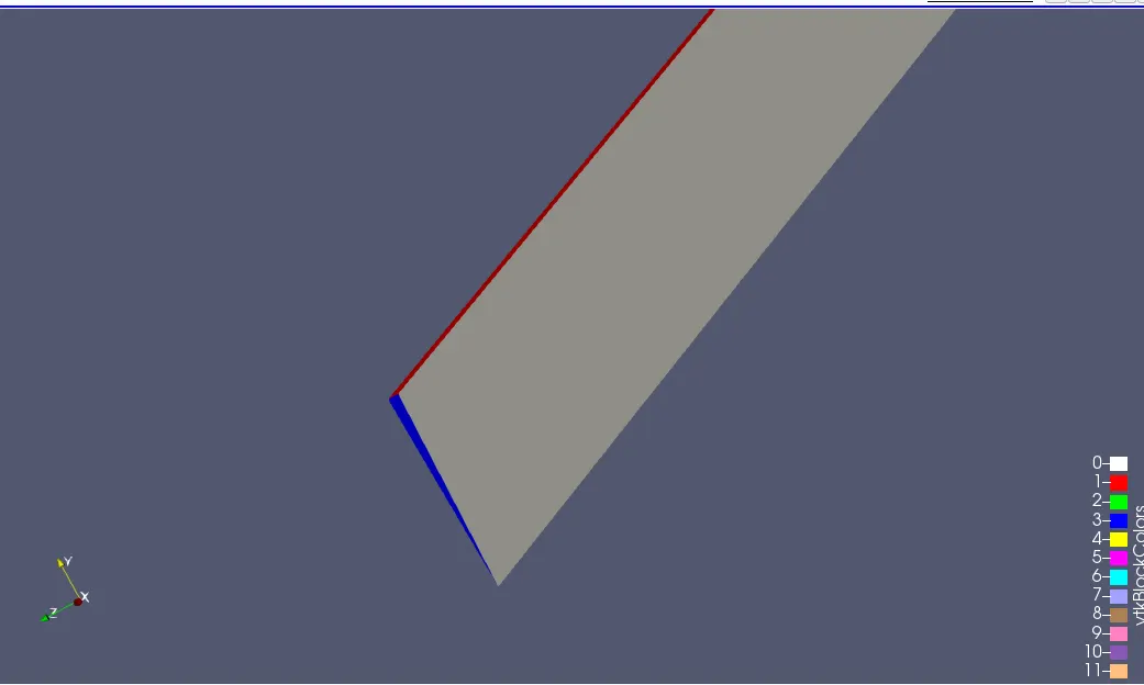
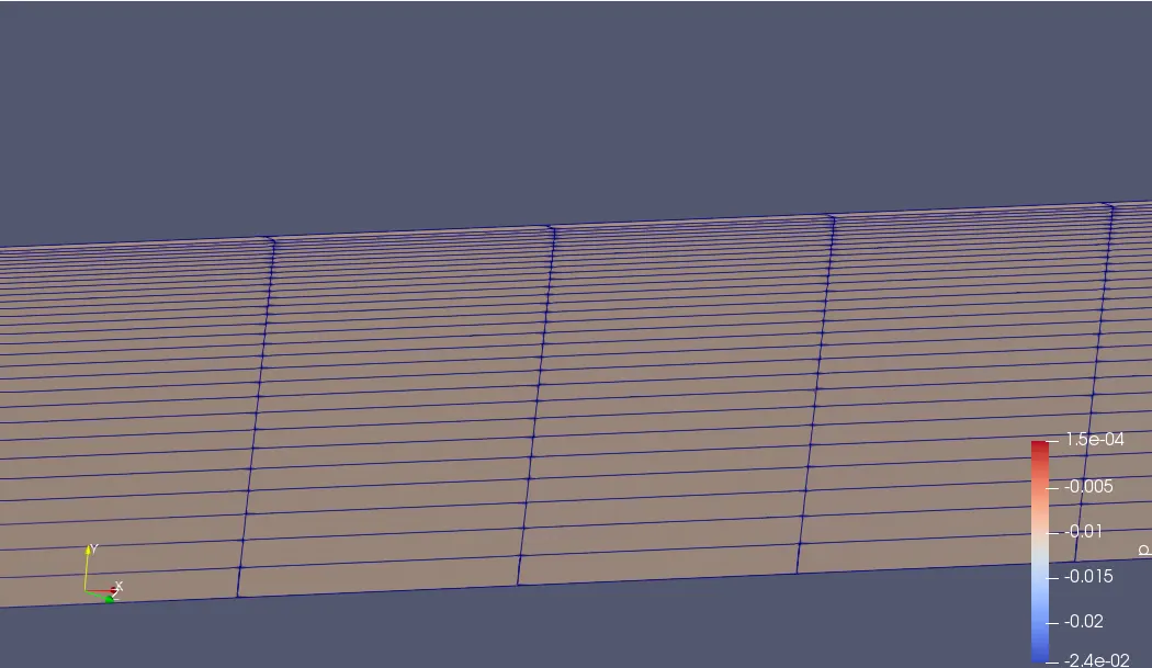
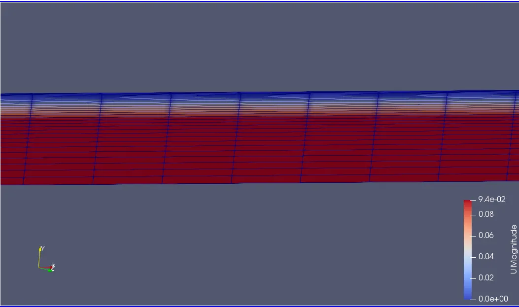
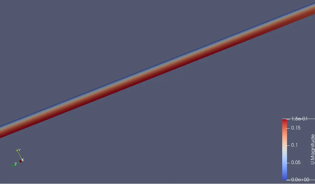
Velocity contour
Generated Plots:
Here also the flow is under developed
Slowly Velocity profile is changing
At 1m the flow is turning fully developed
As per entry length calulation flow will be fully developed after 1.26m and it can be seen at x=1.5m
Shear Stress distribution:
Pressure Drop:
Comparision with Haigen poissule equation:
Analytical solution,
According to Haigen poissule equation
Δp=32μLV/D^2
=(32*8.9*0.0001* 0.869*1.5)/ 0.01^2=79.84 pa
=0.0798 m^2/s^2
And
Vmax=2*Vavg=2*0.1869=0.3738 m/s
Simulation results,
Deltap=0.1 m^2/s^2`
And
Vmax=0.375 m/s