Week 12: Shell and Tube Heat Exchanger simulation
SHELL AND TUBE HEAT EXCHANGER SIMULATION
AIM:
To set the case setup and run the simulation of Shell and Tube Heat Exchanger and make a comparative study between parallel flow and counter flow.
OBJECTIVE:
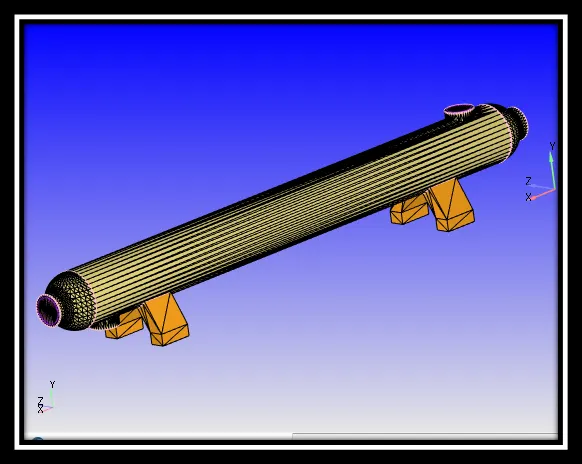
Heat exchangers are one of the mostly used equipment in the process industries. Heat exchangers are used to transfer heat between two process streams. Heat exchanger is required in process which involving cooling, heating, condensation, boiling or evaporation.
Shell and tube heat exchangers consist of a series of tubes. One set of these tubes contains the fluid that must be either heated or cooled. The second fluid runs over the tubes that are being heated or cooled so that it can either provide the heat or absorb the heat required. A set of tubes is called tube bundle and can be made up of several types of tubes: plain, longitudinally finned, etc. Shell and tube heat exchangers are typically used for high pressure applications. This is because the shell and tube heat exchangers are robust due to their shape. Heat exchangers are widely used in industry both for cooling and heating large scale industrial processes. The type and size of heat exchanger used can be made to suit a process depending on the type of fluid, its phase, temperature, density, viscosity, pressure, chemical composition and various other thermodynamic properties.
Parallel flow: In a parallel flow exchanger, as the name suggests, the two fluid streams travel in the same direction. The two streams enter at one end and leave at the other end. The heat exchanger is performing at its best when the outlet temperatures are equal.
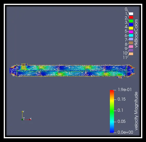
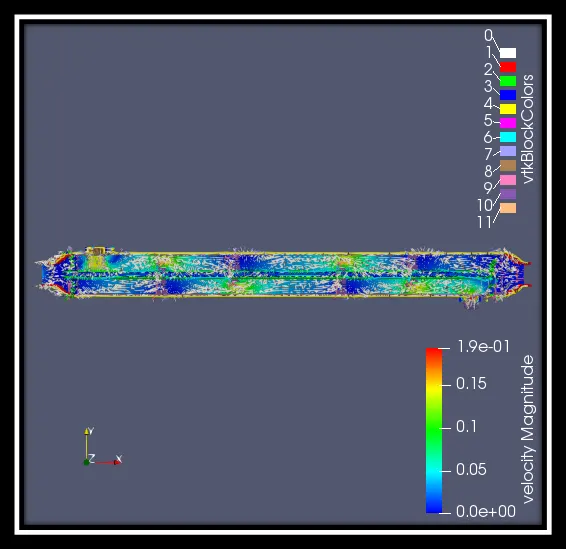
Counter flow: In counter flow heat exchangers the fluids enter the exchanger from opposite end. Counter flow heat exchangers are more efficient than parallel flow heat exchangers because they create a more uniform temperature difference between the fluids, over the entire length of fluid path. Counter flow heat exchangers can allow the cold fluid to exit with a high temperature than the exiting hot fluid.
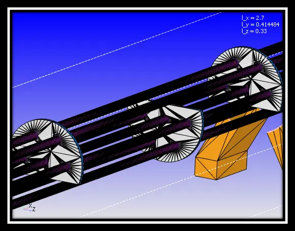
Baffle: Baffles are mainly used in industrial process vessels or tanks such as heat exchanger etc. Baffle is actually an obstructing vane or panel mounted inside the vessel wall. The main purpose of the vessel wall is to reduce the tangential fluid velocity by a mixing impeller. This enhances the mixing efficiency of the fluid within the vessel results by vigorous top to bottom mixing. In absence of baffle the time required to achieve the desired mixing is more or sufficient blending of fluids is not become possible abruptly. In case of heat exchangers baffle not only enhances the heat transfer coefficient but also help in supporting the tube bundle inside the shell and tube heat exchanger. Baffles are placed in shell and tube heat exchanger such that they can give direction to the fluid flow.
There are several reasons for using baffles in heat exchanger, below is a list of functions that baffles are often used for
- To support tubes in heat exchanger
Tubes must be supported at intervals not more than 1.5m; this mainly depends on the diameter of the tube and material of construction. The support intervals can be shorter where flow induced vibrations occur in certain operations.
Supporting the tubes in baffles also prevent mechanical vibrations that can result in tube touching each other and giving rise to leakages and failures mainly near tube sheets.
- To enhance the heat transfer by directing the flow through the shell in a desired pattern
This also increases the turbulence and reduces the stagnant pockets in the heat exchanger. We can also maintain a desired velocity by introducing baffles.
Types of baffles in heat exchanger
There are different types used in heat exchangers, below are the popular ones.
Segmental baffles: A plate type baffles maybe a single segmental, double segmental or triple segmental. With the single and double segmental baffles are most frequently used as they diver the flow most effectively across the tubes.
Disk and doughnut baffle: Has alternating outer rings and inner disk which directs the flow radially across the tube field. They all very effective in pressure drop to heat transfer conversion.
Orifice baffle: In this type of baffles the shell side fluid flows through the clearance between the tube outside diameter and the baffle hole diameter.
Rod baffle: This type is metal rods rather than metal plat baffles. The type is used wherever a very low pressure drop is required. Rob baffles also estimate the tube variations which occur with plate baffles when fluid velocities are high.
The flow in the shell side is mainly parallel to tube axis. Tubes are arranged with square pitch. Rods, with the diameter equal to clearance between the tube rows, are attached to ring supports and placed between alternate tube on both horizontal and vertical directions.
Rod baffles are mainly used when the pressure drop available is very low or there is a pressure drop issue.
Baffle cut: This term is normally expressed in percentage of the shell inside diameter that is no covered by baffle, and is defined as the height of the segment that is cut in each baffle to allow the shell side fluid to flow across the baffle.
The normal recommended value of 20% to 25% cut of shell diameter is used in shell and tube heat exchanger design, the larger the cut the lower the pressure drop however it comes with a disadvantage on the heat transfer as the poorly distributed flow with large eddies is produced causing stagnant areas or dead spaces behind the baffles in the shell, this result in lower heat coefficient. With a smaller cut the percentage drop is higher and the heat transfer coefficient is also higher.
The baffle cut orientation can differ from horizontal cut and vertical cut and varies between 15% and 45% if the shell inside diameter with 45% being a maximum cut for single segmental baffles. Reducing the baffle cut below 20% to increase the shell side heat transfer coefficient or increasing the baffle cut beyond 35% to decrease the shell side pressure drop usually leads to poor design.
CASE SETUP:
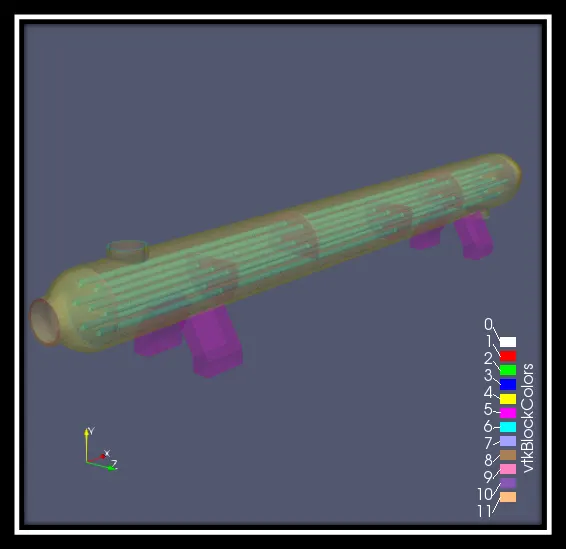
Here in this simulation process, since hot and cold fluids are used Water (H2O) and Ethylene glycol (C2H6O2) is selected in liquid simulation. Silver is selected in solid simulation. In run parameters, transient is selected for solver and the simulation mode will be full hydrodynamic. The liquid flow solver will be incompressible. In solver parameters, Navier-Stokes solver type will be Density based.
In simulation time parameters,
End time: 1.5 sec
Initial time step: 1e-09 sec
Min time step: 1e-09 sec
Max time step: 1.0 sec
In boundary condition,
Outer tube in baffle: Wall motion type- Stationary
Forward side: (solid baffle thickness)
Velocity- Slip
Temperature- Specified value
Reverse side: (solid between tubes)
Velocity- Slip
Temperature- Specified value
Outer shell: Velocity- Wall motion type- Stationary
Surface movement- FIXED
Temperature- 300K
Shell logs: Velocity- Wall motion type- Stationary
Surface movement- FIXED
Temperature- 300K
Shell thickness: Velocity- Wall motion type- Stationary
Surface movement- FIXED
Temperature- 300K
Inner shell oil solid: Wall motion type- Stationary
Forward side: (fluid oil)
Velocity- Law of wall
Temperature- Law of wall
Reverse side: (solid between shells)
Velocity- Slip
Temperature- Specified value
Baffles: Wall motion type- Stationary
Forward side: (fluid oil)
Velocity- Law of wall
Temperature- Law of wall
Reverse side: (solid baffle thickness)
Velocity- Slip
Temperature- Specified value
Baffle thickness: Wall motion type- Stationary
Forward side: (fluid oil)
Velocity- Law of wall
Temperature- Law of wall
Reverse side: (solid baffle thickness)
Velocity- Slip
Temperature- Specified value
Shell thickness-2: Velocity- Wall motion type- Stationary
Surface movement- FIXED
Temperature- 300K
Inner tubes: Wall motion type- Stationary
Forward side: (fluid water)
Velocity- Law of wall
Temperature- Law of wall
Reverse side: (solid between tubes)
Velocity- Slip
Temperature- Specified value
Tube thickness: Wall motion type- Stationary
Forward side: (fluid water)
Velocity- Law of wall
Temperature- Law of wall
Reverse side: (solid between tubes)
Velocity- Slip
Temperature- Specified value
Outer tubes: Wall motion type- Stationary
Forward side: (fluid oil)
Velocity- Law of wall
Temperature- Law of wall
Reverse side: (solid between tubes)
Velocity- Slip
Temperature- Specified value
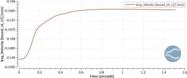
Shell inlet (BOUNDARY ID-12): Pressure- Zero gradient
Velocity- 1.252 kg/s
Temperature- 348K
Tubes inlet (BOUNDARY ID-13): Pressure- Zero gradient
Velocity- 0.037 kg/s
Temperature- 300K
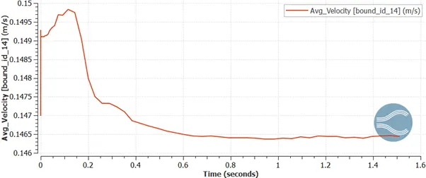
Shell outlet (BONDARY ID-14): Pressure- 101325 Pa
Velocity- Zero gradient
Temperature- 300K
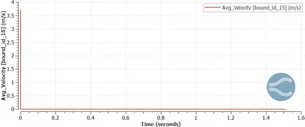
Tubes outlet (BOUNDARY ID-15): Pressure- 101325 Pa
Velocity- Zero gradient
Temperature- 300K
Inner shell water solid: Wall motion type- Stationary
Forward side: (fluid water)
Velocity- Law of wall
Temperature- Law of wall
Reverse side: (solid between shells)
Velocity- Slip
Temperature- Specified value
Baffle face water side: Wall motion type- Stationary
Forward side: (fluid water)
Velocity- Law of wall
Temperature- Law of wall
Reverse side: (solid baffle thickness)
Velocity- Slip
Temperature- Specified value
In events,
|
REGION A |
REGION B |
|
|
Solid between shells |
Solid between tubes |
CLOSE |
|
Fluid oil |
Fluid water |
CLOSE |
|
Solid between shells |
Solid baffle thickness |
CLOSE |
|
Solid baffle thickness |
Solid between tubes |
CLOSE |
In physical mode,
Turbulence model: RNG k-ε
In super cycle modelling
Begin storing super cycle data: 0.05 sec
Solid side heat transfer solver: Steady state solver
Time length of each cycle stage: 0.05 sec
In grid control,
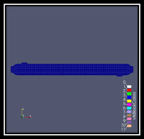
Base grid: dx- 0.01m
dy- 0.01m
dz- 0.01m
Surface with edges:
COUNTER FLOW:
Pressure contours:
Pressure contours: https://youtu.be/9kUAkCNzfjg
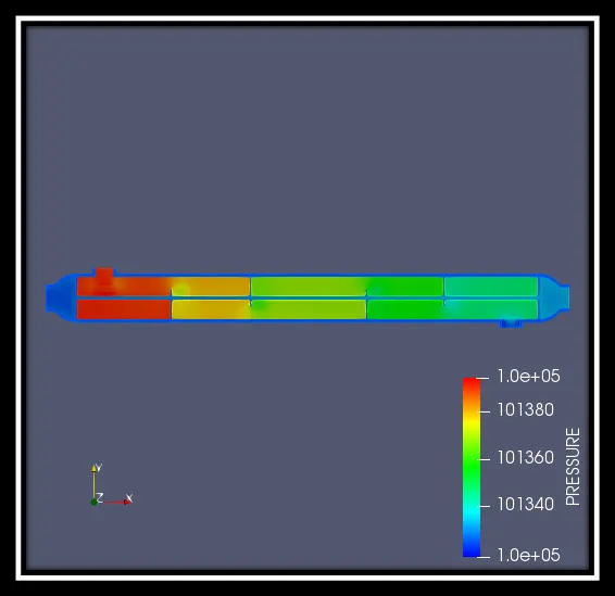
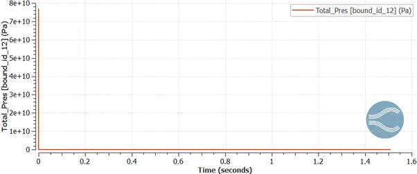
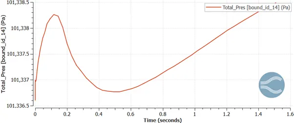
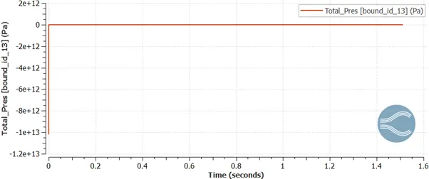
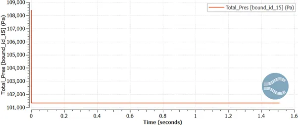
Initially, before releasing the fluids in to the shell and tube the pressure looks very high. When the fluids are released the pressure at the shell inlet port gradually decreases and comes to zero point. Inside the shell, the pressure gradually decreases but, when it hits the baffle the pressure gets slightly high and it flows across every baffle to and comes out from the shell outlet port. Since the water is released through the tube inlet port, the cold water decreases the temperature of hot oil because of convection. Due to this, the pressure at the tube surface regions is very low.
Shell ports:
Inlet:
Outlet:
Tube Ports:
Inlet:
Outlet:
Velocity contours:
Velocity contours: https://youtu.be/P3uHZotXOJA
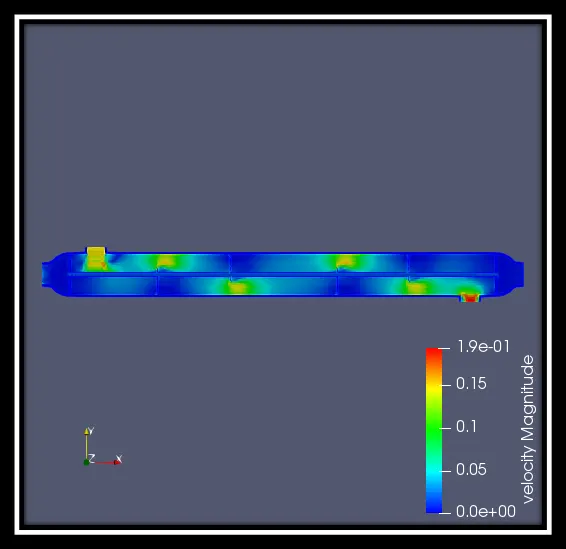
Initially, the water is been released through the tubes which causes the velocity is get increased and when it flows through the tubes the velocity gradually decreases and comes to zero point. When the oil is released through shell inlet port the velocity gets decreased but when it hits the baffle and it slides down and then moves. This makes the velocity to decrease at the surface of baffle and when it slides down the velocity suddenly boost up from 0m/s to 1 or 1.5m/s. As you can see the velocity is high only at point of down plate of baffle and the shell inlet and outlet ports.
Shell ports:
Inlet:
Outlet:
Tube ports:
Inlet:
Outlet:
TOTAL HEAT TRANFSER BETWEEN HOT OIL AND TUBE THICKNESS:
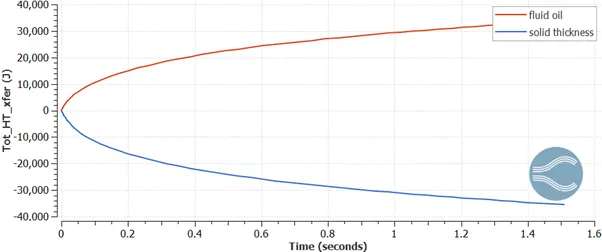
As you can see, the heat released by hot oil and the heat absorbed by the solid thickness is same and the value is 35,537 J.
TOTAL HEAT TRANSFER BETWEEN TUBE THICKNESS AND COLD WATER:
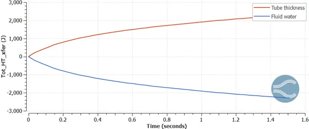
As you can see, the heat released by the cold water is same as the heat absorbed by the tube thickness and the value is 2,290 J.
As we can see from the above plots that there is a heavy loss of heat as lot of heat is being absorbed by the solid.
Heat released by the hot oil= 35,537 J
Heat released by the cold water= 2,290J
Heat loss or heat absorbed by the solid= 35,537 – 2,290= 33,247 J
This is the major drawback in any heat exchanger and therefore there is a need to select the material for the solid carefully which has high conductivity so that the heat loss will be reduced.
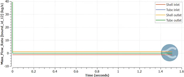
Mass flow rate:
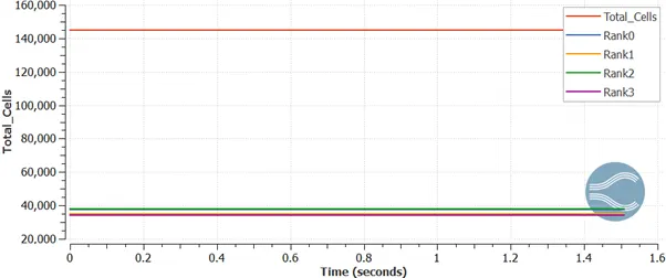
Total cell count:
PARALLEL FLOW:
Pressure contours: https://youtu.be/zZiSflXfgyI
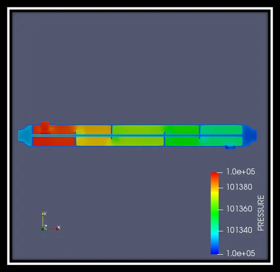
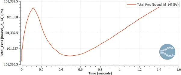
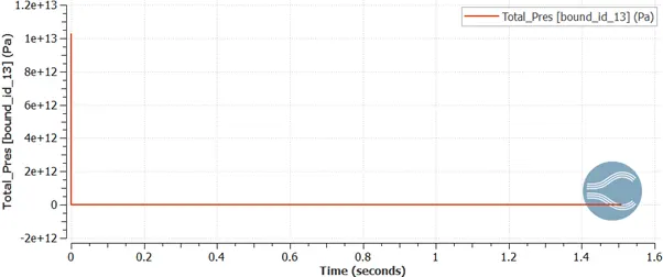
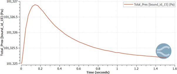
Initially, the pressure at the tube inlet port is very low and pressure at shell inlet port is very low and both the outlets are very high. As these fluids flow the pressure deceases. The difference between the above flows is that two fluids flow in the same direction.
Shell ports:
Inlet:
Outlet:
Tube ports:
Inlet:
Outlet:
Velocity contours:
Velocity contours: https://youtu.be/RNMIdqh_Hi4
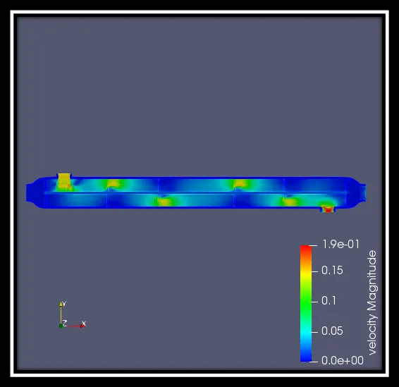
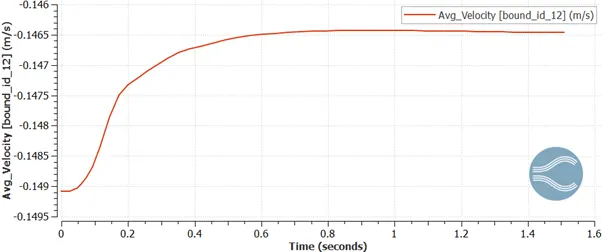
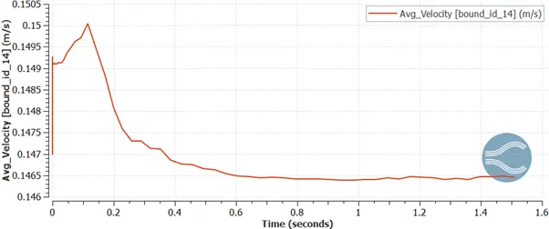
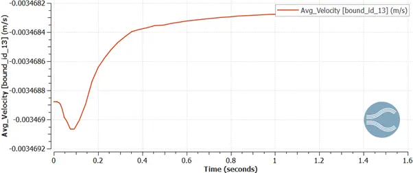
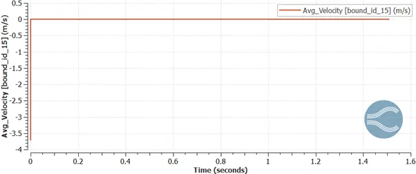
As here, the above velocity details are quite similar but only one difference is the fluid flows in the same direction.
Shell ports:
Inlet:
Outlet:
Tube ports:
Inlet:
Outlet:
TOTAL HEAT TRANSFER BETWEEN TUBE THICKNESS AND HOT OIL:
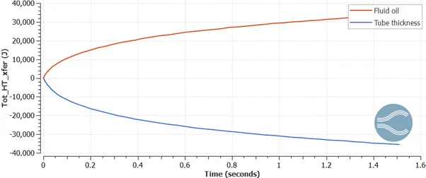
As you can see, the heat released by hot oil and the heat absorbed by the solid thickness is same and the value is 33,905 J.
TOTAL HEAT TRANSFER BETWWNE TUBE THICKNESS AND COLD WATER:
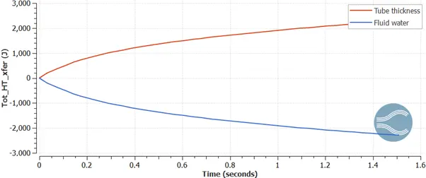
As you can see, the heat released by the cold water is same as the heat absorbed by the tube thickness and the value is 2,291 J.
As we can see from the above plots that there is a heavy loss of heat as lot of heat is being absorbed by the solid.
Heat released by the hot oil= 33,905 J
Heat released by the cold water= 2,291J
Heat loss or heat absorbed by the solid= 33,905 – 2,291= 31,614 J
This is the major drawback in any heat exchanger and therefore there is a need to select the material for the solid carefully which has high conductivity so that the heat loss will be reduced.
Mass flow rate:
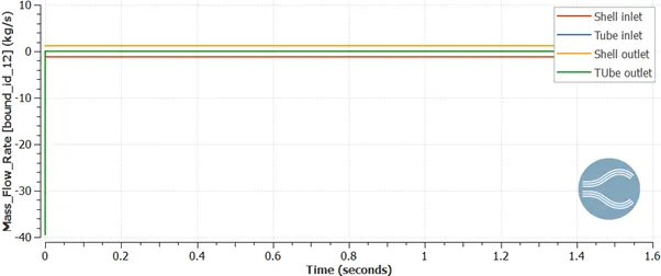
Total cell count:
CALCULATIONS FOR BOTH PARALLEL AND COUNTER FLOW
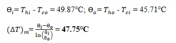
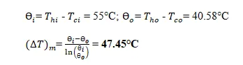
LMTD- Logarithmic Mean Temperature Difference : In order to solve heat exchanger problems, logarithmic mean temperature difference is often used to determine the temperature driving force for heat transfer in heat exchanger. LMTD is introduced due to the fact; the temperature change can takes place across the heat exchanger from the entrance to exit is not linear.
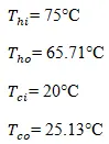
For counter flow,
For parallel flow,
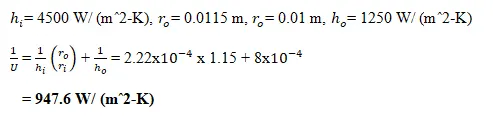
Overall heat transfer co-efficient (U): The overall heat transfer co-efficient is employed in calculating the rate of heat transfer from one fluid at an average temperature and through a solid surface to a second fluid at an average temperature.
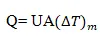
Heat Transfer Rate (Q): The heat flow rate is defined as the amount of heat transferred per unit time in the material. The heat flow rate in a rod depends on the cross-sectional area of the rod, the temperature difference between both the ends and the length of the rod.
For counter flow,
Q= 947 x 3.14 x (0.023-0.02) x 2.4 x 47.75
= 1022.31 W
For parallel flow,
Q= 947 x 3.14 x (0.023-0.02) x 2.4 x 47.45
= 1015.89 W
Mass flow rate (m): The mass flow rate is the mass of liquid substance passing per unit time. In other words, the mass flow rate is defined as the rate of movement of liquid pass through a unit area. The mass flow is directly dependent on the density, velocity of the liquid and area of cross section. It is the movement of mass per unit time.
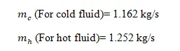
Velocity of the fluid (V): Flow velocity is the vector field that is used to describe fluid motion in a mathematical manner. The entire length of the flow velocity is referred to as flow speed. Flow velocity in fluids is the vector field that provides the velocity of the fluids at a certain time and position.

For cold fluid,
m= 1.162 kg/s; ρ= 1000 kg/mˆ3; A= 0.022 mˆ2
V= 0.052 m/s
For hot fluid,
m= 1.252 kg/s; ρ= 1110 kg/mˆ3; A= 0.022 mˆ2
V= 0.051 m/s
Under comparable conditions, more heat is transferred in the counter flow arrangement than in the parallel flow heat exchanger.
The counter flow heat exchanger has three significant advantages over the parallel flow design. First, the more uniform temperature difference between the two fluids minimizes the thermal stresses throughout the exchanger. Second, the outlet temperature of the cold fluid can approach the highest temperature of the hot fluid. Third, the more uniform temperature difference produces a more uniform rate of heat transfer throughout the heat exchanger. So, from this we can say that counter flow is better than parallel flow.
Drawbacks of shell and tube heat exchanger:
- Heat exchanger effectiveness is less.
- Cleaning and maintenance is troublesome since a tube cooler requires enough clearance at one end to remove the tube nest.
- Capacity of tube cooler cannot be increased.
- Requires more space in comparison to plate coolers
Fouling factors: We know the surface of the heat exchangers do not remain clean after it has been in use for some time. The surface becomes fouled with scaling or deposits. The effects of these deposits affecting the value of overall heat transfer co-efficient. This effect is taken care of by introducing an additional thermal resistance called the fouling resistance.
CONCLUSION:
So, the simulation process of shell and tube heat exchanger is done with both counter and parallel flow. The results show that, the counter flow is better than the parallel flow.