Meshing of Spare Tyre Floor
Aim
To discretize the wheel floor panel of a car for the virtual analysis.
Objective
To prepare the wheel floor panel of a car for the virtual analysis by discretizing it into a finite number of elements.
PROCEDURE
The wheel floor panel model was a single sheet metal part of 0.75 units. The panel had several smaller and bigger geometrical features, as can be seen in fig. 1.
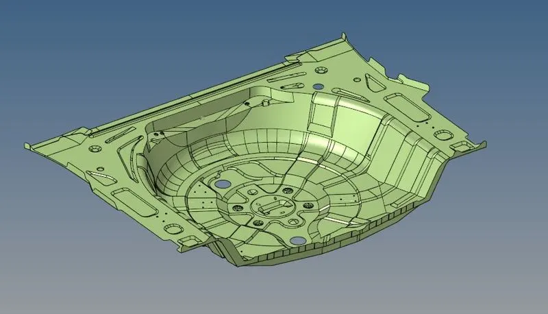
Figure 1: Wheel floor panel.
- Geometry Clean-up
The primary stage of meshing any part is to clean the geometry. There were some errors in the geometry related to the presence of free-edges or absence of surface, duplicate faces, and triple lines. Errors that could make a disturbance in obtaining the mid-surface were cleared. Remaining errors were kept as it is, for saving the time.
In 2d meshing, the elements are deployed on a surface of no thickness or midsurface. Solid parts have no role in 2d meshing. Therefore, before cleaning the geometry, it is necessary to check if any solids present in the model. If present, it should be deleted. In this model, no solids were present
- Extracting Mid-surface
After cleaning the geometry, the next stage of the discretization procedure is to obtain the mid-surface or the middle surface of the complete part. The mid-surface is the surface with no thickness. A property has to be assigned separately to that surface, which defines its thickness. The reason behind extracting the mid-surface is to reduce the computational time. If the part has meshed with 3-d elements, it would take more computational time to solve the problem compare to 2-d elements. For the sheet metal and plastic components with thickness less than 5-6 mm, generally, 2-d elements are used. Here the thickness of the sheet was 0.75 units. Thus, meshing with 2-d elements was a wise decision.
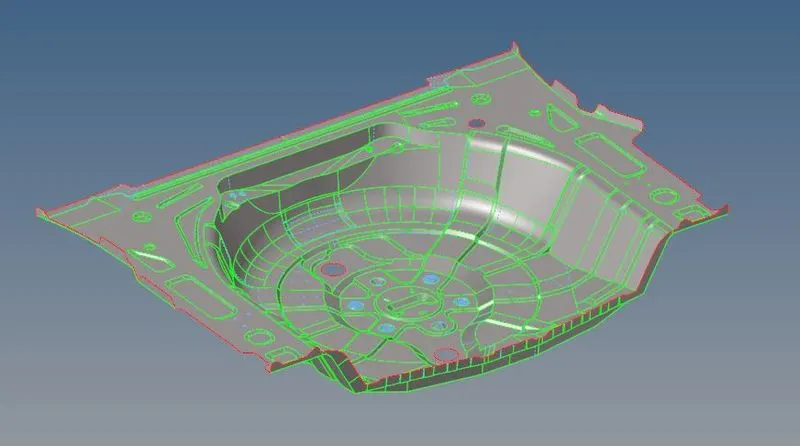
Figure 2: Mid-surface of the wheel floor panel.
In this work, a mid-surface was obtained automatically. However, some faces couldn't obtain perfectly. So mid-surface of such faces were then obtained manually, to correct the geometry. In fig. 2, some faces were symmetric while some were not. In such cases, the elements that would be obtained can be reflected for the symmetric faces.
- Preparation for meshing
While meshing a part, the flow of elements has to be smooth. It provides a smooth flow of energy. To maintain the smooth flow of energy some other criteria are like no trias should be facing each other, trias shouldn’t be present at the edge, etc. Rotating quads are also not required. Tria elements are generally kept very limited. In this work, trias are limited to 10%.
To mesh the complete geometry with the smooth flow of elements, the geometry was split into several smaller parts bearing in mind that it will not disturb any feature of the geometry. Thus, meshing and observation of the smaller parts become easier.
- Setting Quality Criteria
A criterion is always set for the quality of elements based on some parameters viz. the aspect ratio, the warpage, the minimum, and maximum length, etc. of an element. Depending on the criteria, the part meshes. The criteria provided for this part is as shown below table:
Table 1: Quality criteria for elements.
|
Target length |
5 mm |
|
Aspect |
5 |
|
Skewness |
45 |
|
Warpage |
15 |
|
Taper |
0.5 |
|
Minimum length |
2 units |
|
Maximum length |
8 units |
|
Minimum Quad Angle |
45 |
|
Maximum Quad Angle |
135 |
|
Minimum Tria Angle |
20 |
|
Maximum Tria Angle |
120 |
|
Tria Percentage |
10% |
The quality of the elements required is set by clicking the Preferences → Criteria file settings, in the menu bar. A dialog box would open as shown in fig. 3 in which a required quality criterion can be set.
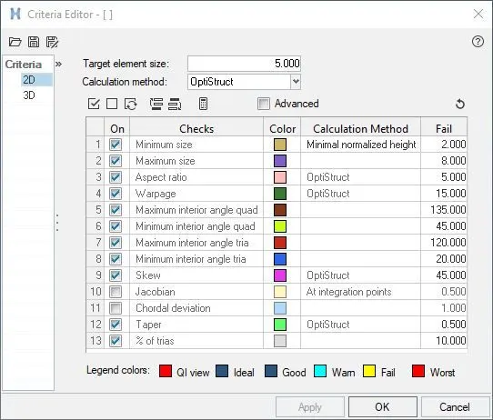
Figure 3: Dialog box that opens after clicking the Preferences→Criteria file settings in the menu bar to set quality parameters of elements.
- Discretization or meshing
Once the quality of elements is set, the next stage is the meshing of the model. To mesh the model, there is an option called ‘automesh’ in the 2D section (shortcut is F12). Using this tool, the faces of the model are meshed one-by-one. The figure below shows the meshed wheel floor panel model.
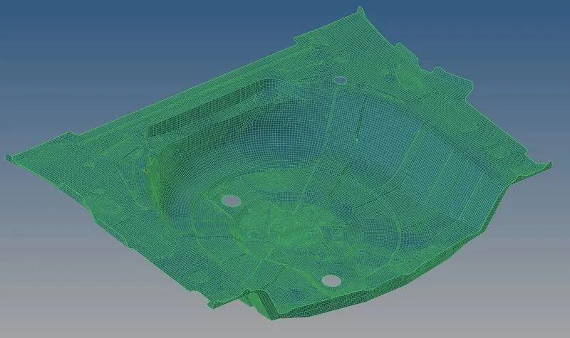
Figure 4: Discretized wheel floor panel.
- Quality Check
After completing the meshing part, the last stage of the process is to check if all the elements are within the set criteria or not. To do that, there is an option called ‘elems check’ in the Tool section (shortcut F10). When clicked, a window of a set of quality parameters opens as shown in fig. 9.

Figure 9: Window to check failed elements.
Once the failed elements are found it has to be corrected manually. It can be done by using the different tools available in 2D →qualityindex→cleanup tools, as shown in fig. 10. Or one can also do that using 2D → elem cleanup. In this work, 4 elements have failed for warpage, 27 for aspect, 45 for skew, 8 for taper, and 83 for minimum length. All these failed elements are due to space constraints, which couldn’t be cleared.
CONCLUSION
Meshing a model is the primary and important stage of virtual testing. Thus, while meshing the geometry with quad/tria elements, attention should be given to maintain the mesh flow. Because, if it has gone wrong, the result would be inaccurate and thus would be the waste of time and money.