Week 12:Project 2-Meshing of Rear Wheel Holder challenge
PROJECT - 2: Meshing of Rear Wheel Holder challenge
AIM:
- To mesh the given rear wheel holder model by following the given criteria condition.
- To assign thickness to the model mesh.
OBJECTIVE:
- Meshing model by following criteria condition.
- Handling various tools in Hypermesh for mesh quality correction.
- Study about various model checking methods.
THEORY:
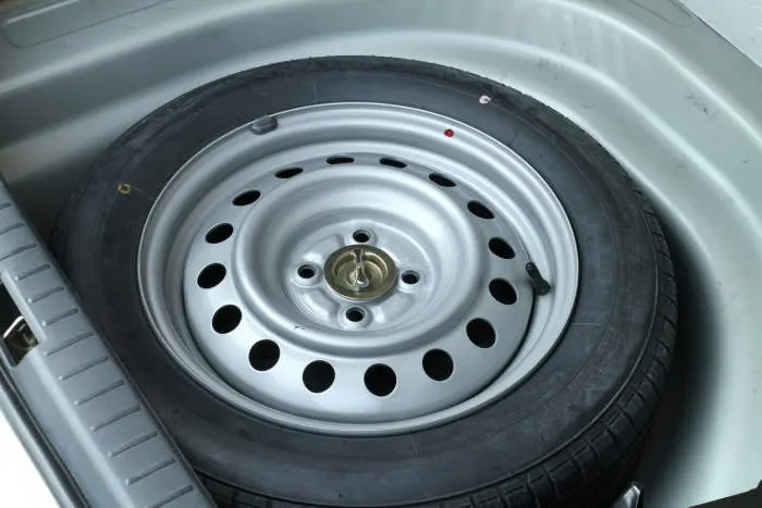
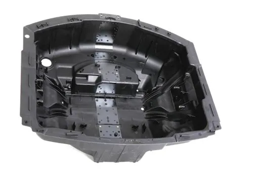
SPARE WHEEL WELL: In most passenger cars, there is a recessed storage space in the trunk for a spare wheel mounted tire, a jack and a lug wrench. Traditionally produced in stamped steel, and more recently in aluminium, this spare wheel well (SWW, also known as a spare wheel baffle) is a large, heavy, tub-like component that also plays a role in vehicle structure and crash safety.
The stepney spare wheel is invented Thomas Morris Davies in 1904, at that time time early motor cars were made whithout spare wheels, so a punture was an invent dreaded by all drivers. So Mr. Davies brilliant idea was to make a spokeless wheel rim fitted with an inflated tyre. A spare tyre or stepney is an additional tire/tyre carried in a motor vehicle as a replacement for one that goes flat, has a blowout, or has another emergency. A structural shear panel for forming floor panel for support by a vehicle frame is formed by a composite of topn and bottom sheets and core with the vacuum infused resin. The core is formed of top and bottom layers each formed from a honeycomb panel defining an array of hexagonal tubular cells with wall which extended in the thickness direction filled with a foam material.
GIVEN CRITERIA:
Target Element Length = 5 Units
| S.N | Quality Criteria | Value |
| 1 | Aspect Ratio | 5 |
| 2 | Skewness | 45 |
| 3 | Warping | 15 |
| 4 | Taper | 0.5 |
| 5 | Min. Length | 2 Units |
| 6 | Max. Length | 8 Units |
| 7 | Min angle Quad | 45 |
| 8 | Max angle Quad | 135 |
| 9 | Min angle Tria | 20 |
| 10 | Max angle Tria | 120 |
| 10 | Tria % | 10 |
PROCEDURE:
Step - 1: Importing the model
- Import the given model into HyperWorks using the option File → Import → Import geometry → Choose the file and its type → Import.
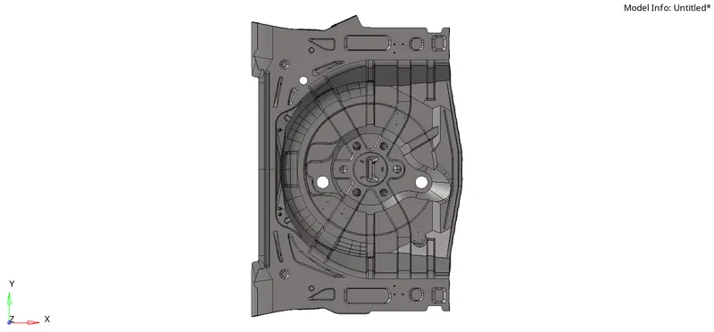
Fig.1: Imported model
Step -2: Geometry cleanup
- The imported model may need Surface patch up, creating new surfaces, eliminating of triple cons in unwanted area, converting single cons to double cons in necessary area.
-
The rear wheel holder is a sheet metal component and it has a uniform thickness in it. The cleaning process consists of; closing the small holes, toggling the unwanted lines in the surfaces, defeaturing the small dia. fillet areas, splitting the surfaces into parts, filling the empty surface, add/remove the points in the lines, delete the unwanted surfaces.
- We can view the model in 'By Topo' and in wireframe to check the red lines.
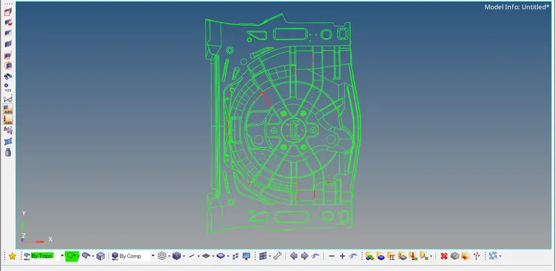
Fig.2: Wireframe geometry view
Here we can see many places with red lines. So, we need to correct them manually. We can use various tools like replace, toggle, filler surf etc. from quick edit tab and edge edit tab for correcting these areas.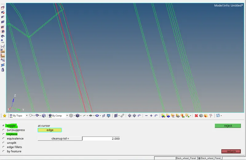
Fig.3: Edge edit tab - Remove the buttons which are shown below because it will be difficult to capture that area as well mesh flow will not be proper. Except this feature, all the other features should be captured with proper element quality.
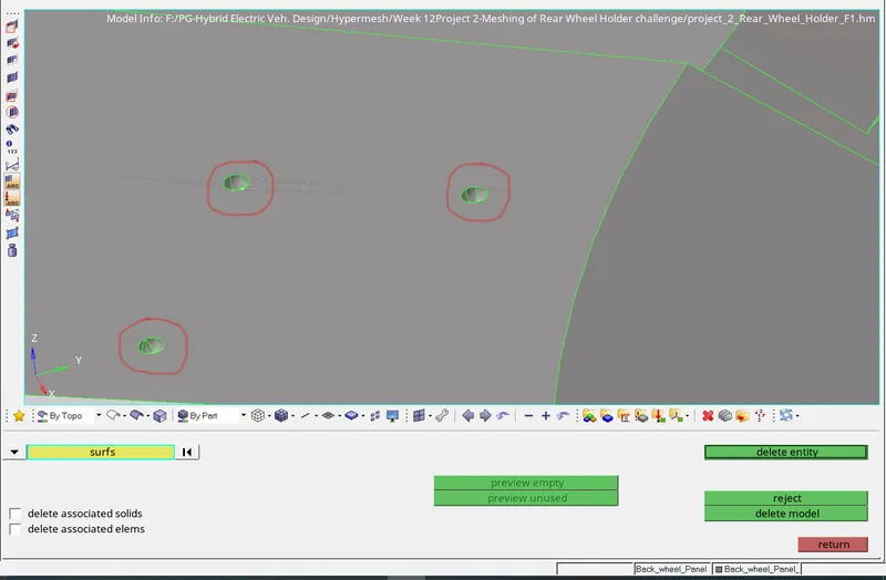
Fig.4: Removing buttons
After removing these buttons, we have to fill those areas with surface by using 'filler surf'. Geom. → quick edit → Filler surf.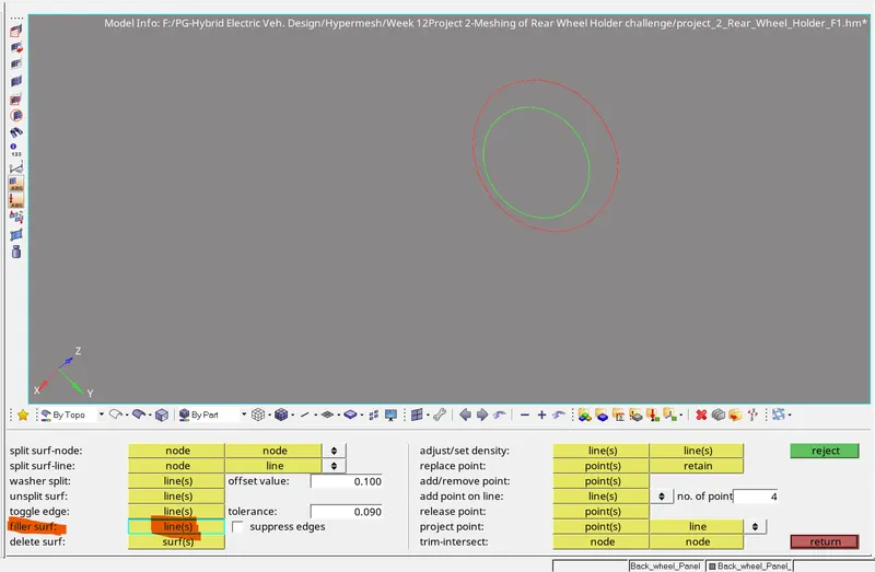
Fig.5: Filler surf tool
Step -3: Criteria and Parameter file setting
- We need to set criteria as well as parameter file. As we are proceeding this with batch mesh, we have to save these criteria and parameter file.
Preferences → criteria file settings and parameter file settings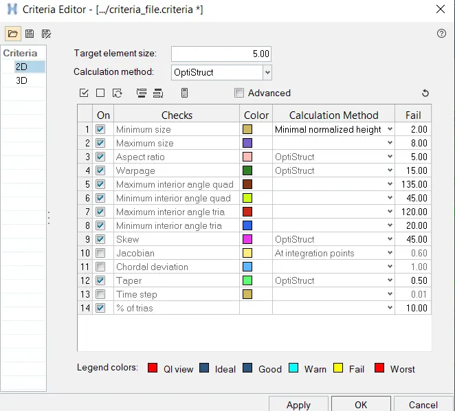
Fig.6: Criteria file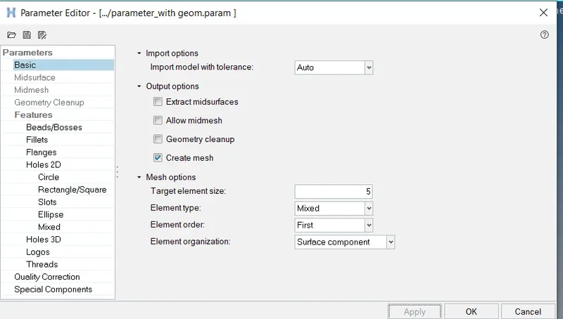
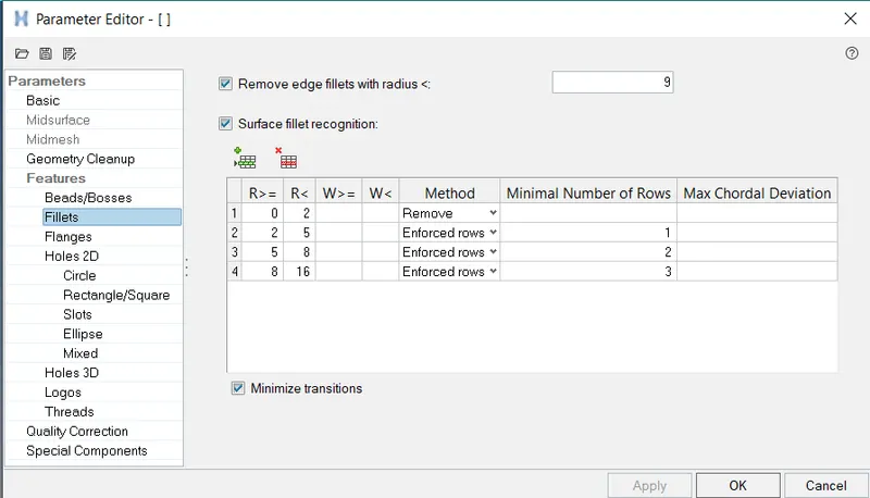
Fig.7: Parameter file
For this model, we are doing mannual geometry cleanup. So untick it from parameter setting.
Step -4: Midsurface generation
- Since, the given model is sheet metal, we can perform auto-midsurface.
Geom. → midsurface → select automidsurface, extraction option as 'offset' , then select autoextraction → select surface → extract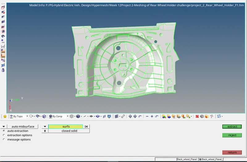
Fig.8: Midsurface generation - Rename the midsurface by adding the thickness value in name. Compare the midsurface with parent body to check whether the midsurface is captured all the features or not. Check for any defects in the midsurface and if there correct those.
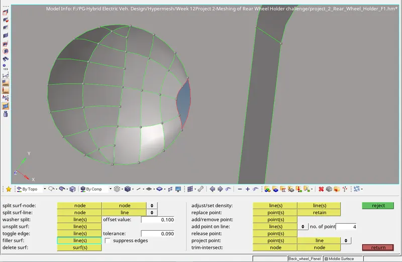
Fig.9: Correcting midsurface using 'filler surf' tool
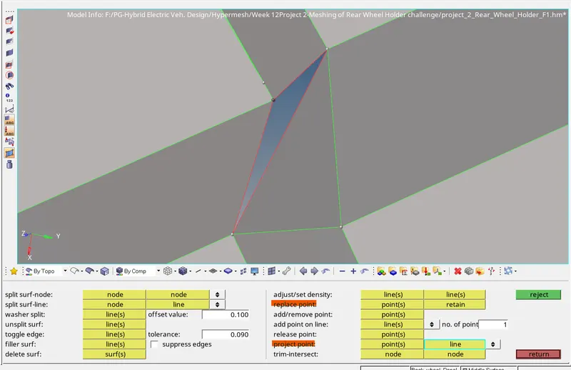
Fig.10: using replace and project point tool
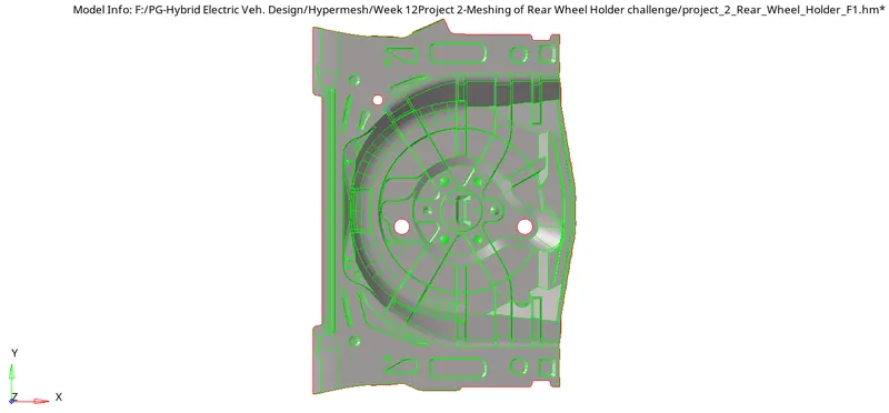
Fig.11: Midsurface created - Before doing meshing, we have to avoid places where element may fail quality. So, toggle unwanted lines and remove unwanted points, make cut in the surface for better meshing (If needed). We can use 'quick edit' tool tab for this purpose.
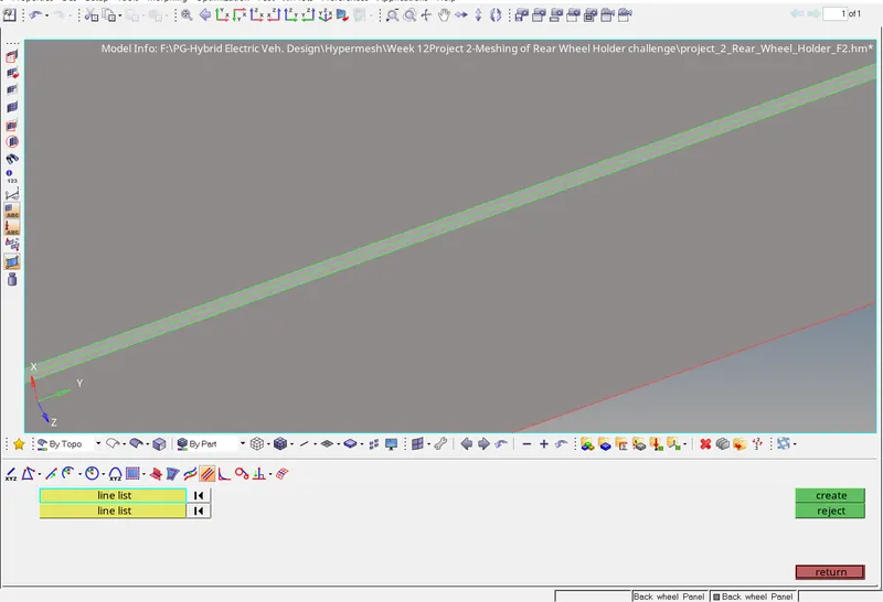
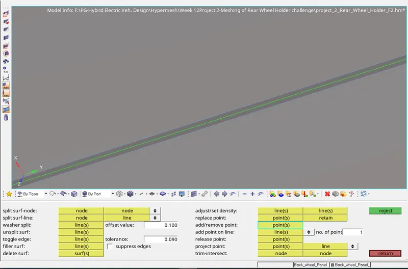
Fig.12: Creating a midline cut and toggling lines where there is a chance of minimum element length failure.
Step - 5: Meshing
- Now we need to proceed to mesh the midusrface. To perform meshing on the component, we need to use the command of Automesh (Shortcut-F12) under the 2D Tab. Here, we are using batch-meshing.
2D → Automesh → Batchmesh/ QI optimize → Select the surface displayed → Select criteria as well as parameter file we saved before → mesh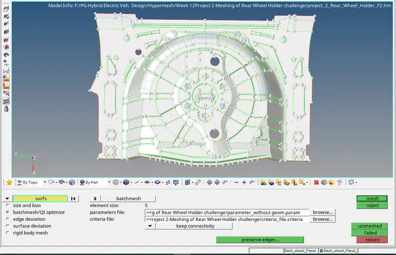
Fig.13: Batchmeshing - After meshing, check whether the elements are created in all area in the surface. Check the mesh created and use 'rebuild' tool at required region. Correct the mesh flow. Try to avoid back-to-back tria, tria touching each other, rotating quads and trias at free edge. Use rebuild, element edit, replace, drag tria tools for that purpose.
Step - 6: Mesh Quality checking
- Once after completing the mesh, we need to check and ensure that the mesh so generated is as per the given quality criteria.
- For this we use the option 2D → qualityindex as well as Tool → check elems. There might be deviations in some or all of the quality criteria which we need to correct by using the various options available in the cleanup tool options available in the qualityindex. Also, we can use element edit, replace node options as well for correcting failing elements.

Fig.14: Qualityindex cleanup tools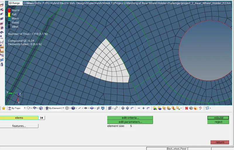
Fig.15: Using rebuild tool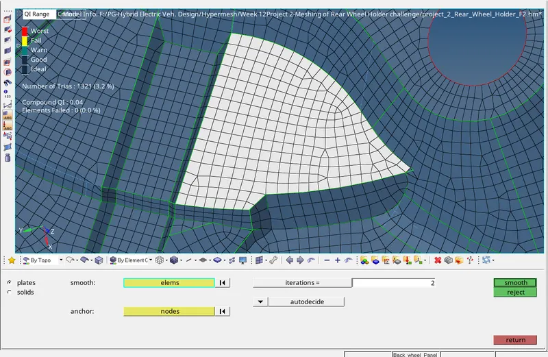
Fig.16: Using smooth tool - We can view the element color mode as 'By element quality'. It will show the elements which fails the criteria or quality.
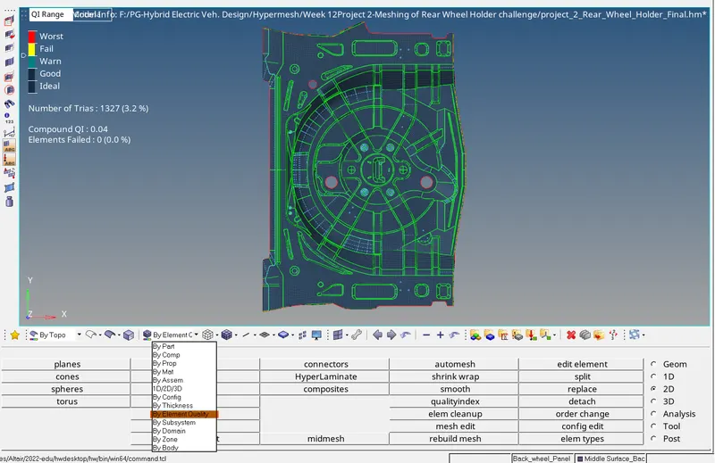
Fig.17: Changing element color mode - We can also use 'distance' and 'element edit' tools for correcting failing elements.
(Note: If we are adding any lines nodes or creating T connection to the meshed surface, it will distort the mesh created. To avoid this use, disassociate option from topology revision; Preferences → topology revision option → select 2D mesh as disassociate. But this operation may result in disconnection of elements. So, use replace node option to make connection and perform 'rebuild tool' on those areas to get a better meshing.)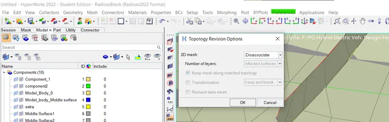
Fig.18: Topology Revision option
Step - 7: Assigning property and material
- The next step is to assign thickness to the model. The first step when assigning thickness is to measure the thickness at various spots in the model by using 'distance' tool.
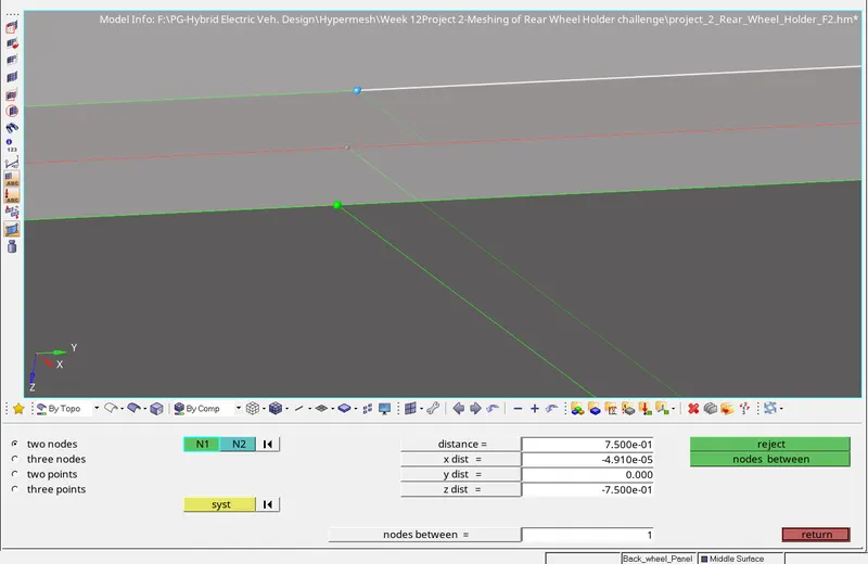
Fig.19: Thickness checking - Now to assign proper thickness to the elements, we need to create properties and change the value of thickness for that property. To create a property, we again right click on the tree and select the create option and under this option we need to select the option of Property. The option Material also available in the Create option. The material is given as steel with card image as MAT1.
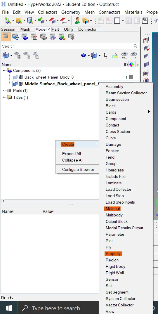
Fig.20: Creating material and property tab - After we create the property, we then need to change the value of thickness for this property. The value of thickness is "T" in the property tab. The thickness of the component is 0.75 units. We need to change the value of "T" to 0.75.
- After creating both property as well as material tab assign them to the mesh we created.
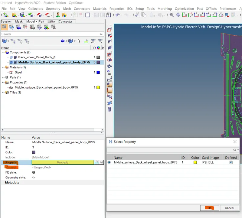
Fig.21: Assigning thickness and material - We can view the element as 2D detailed element representation or viewing element by thickness (From element color mode) to check whether the thickness is assigned or not.
Step - 8: Model check
- Check for edges: The components are checked for edges.
Tools → edges → select element dispalyed → find edges,
If no error noticed, delete edges. select element again → preview equivalent → return
otherwise, you can click on equivalence and try to fill that. we can also use replace node option.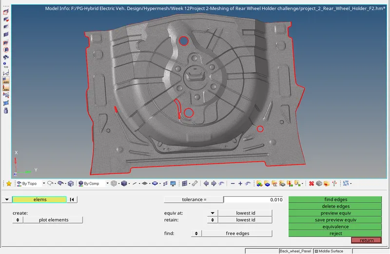
Fig.22: Errors find during edge checking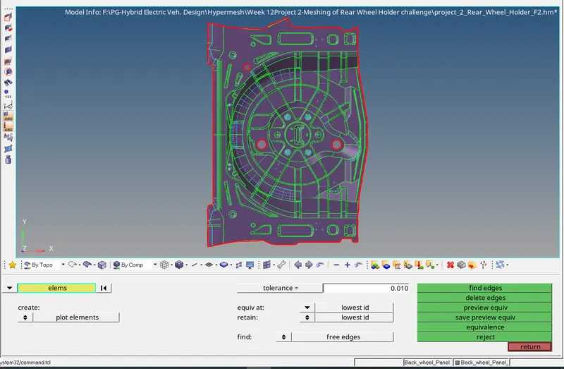
Fig.23: After correcting edges - Check for Normal: The normal direction is checked by following the below steps,
Tools → Normals → display → we can choose color display or vector display.
The defected element's normals are reversed using the same tool by selecting the element.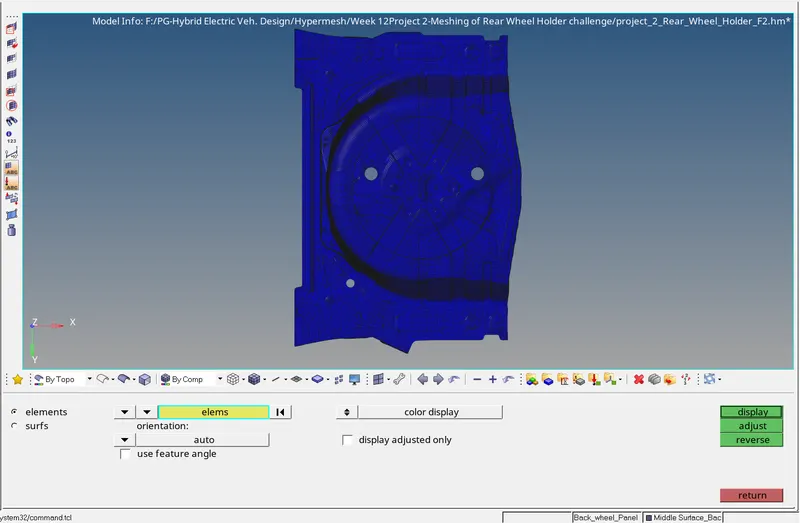
Fig.24: Checking normal - Element to surface check: To check how the element is captured the surface geometry.
mesh → check → elements → comparison → click on element tab shown in source entity → Select element displayed → Proceeds → click surface tab in the target entity → select surface displayed → Tolerance = 0.2 → Run
The yellow and pink color in mesh is okay. If there is defect, we used project tool to rectify it.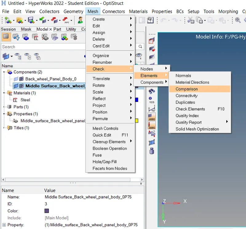
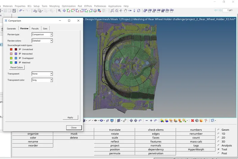
Fig.25: Element to surface comparison
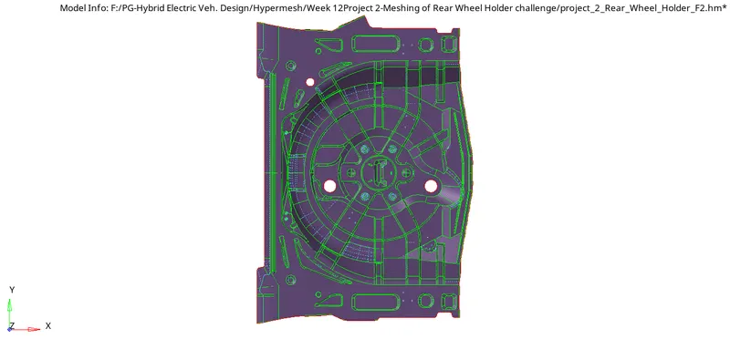
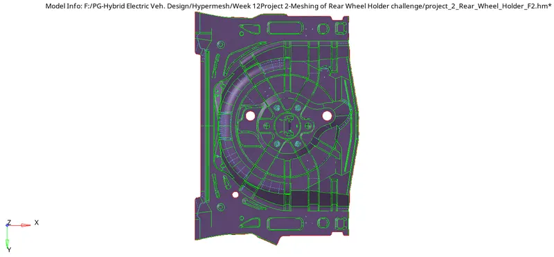
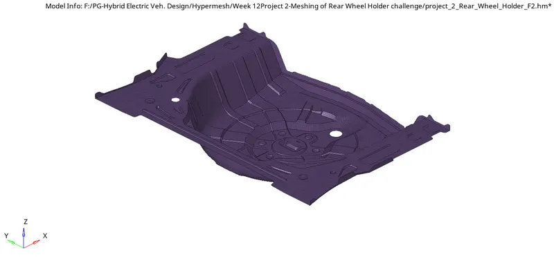
FINAL MODEL:
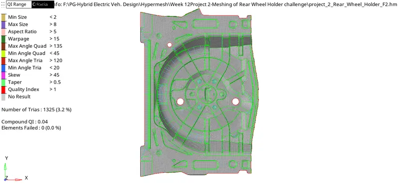
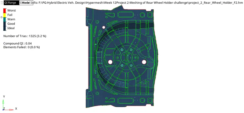
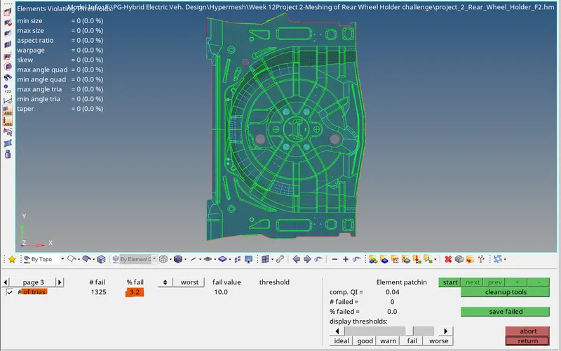
- QUALITY CHECK:
- MESHED MODEL:
RESULT:
The given rear wheel holder model is meshed by following the quality criteria with proper mesh flow and the thickness is assigned to the mesh.
CONCLUSION:
This project develops better understanding of tools and methods in Hypermesh for meshing and element quality correcting. It also reminds us the importance of creating midsurface without defects for getting proper mesh with quality and connectivity. This project also provides better experience in manual geometry clean-up, handling trias at critical areas and element quality correction.