Week 12:Project 2-Meshing of Rear Wheel Holder challenge
Aim:- To mesh the given Rear Wheel Holder with given quality criteria.
Objective:-
* Extract the midsurface of given component.
* Mesh the model with given quality criteria.
* Check the elements quality.
* Assign the thickness to the component.
Procedure:-
1. Import The Model :
* Import the model in iges format ( file - import - geometry )
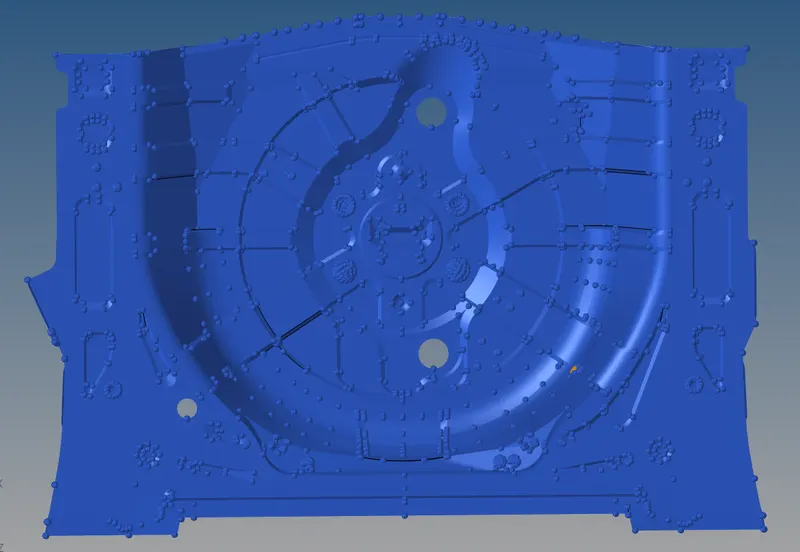
2. Geometry cleanup:
* After importing the model we have to inspect the geometry whether it in ok or not.
* For this we enable the topo mode and click on wireframe tool and we clearly observed problems in geometry such as gap in surface , free edges and overlaped surface, missing surfaces.
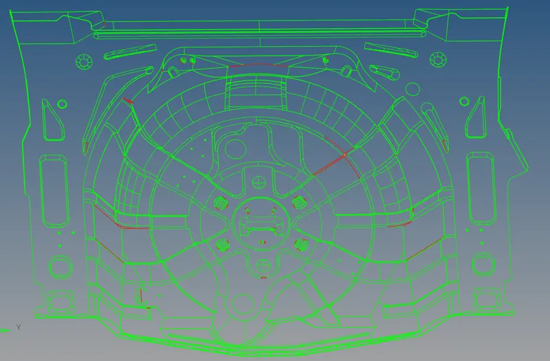
* In above image we can easily ovserved that there are lot of issues in geometry.
* We use different tools such as quick edit tool , surface and surface edit tool and other essential tools and do geometry cleanup.
3. Extraction Of Mid-Surface :
* After ensurign parent geometry is cleaned we go for extraction of midsurface.
* For extraction we use auto midsurface extraction tool and we use offset+planes+sweeps as a extraction option. ( Geom - midsurface - auto midsurface )
* After extraction of midsurface we check newly created midsurface whether it is extracted properly or not , we check missing surface and free edges and other observations such as shape same as parent geometry and surface in on mid or not.
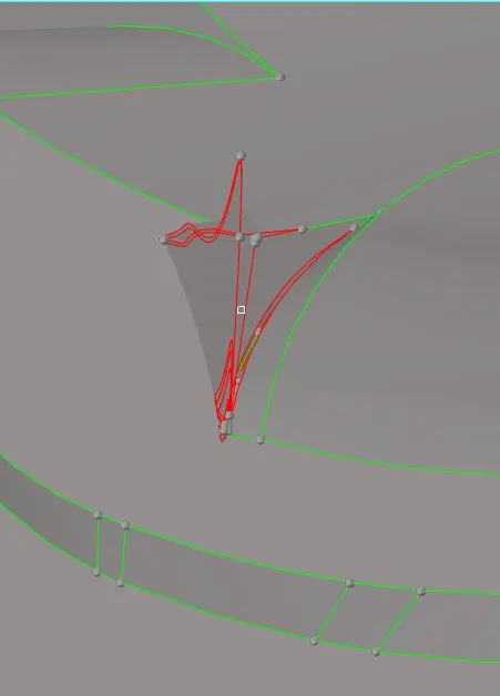
* If we extract the midsurface automatically we get mid surface as well as some geometrical issue. as a example we can see above image there is extra uneven surface is also created so we have to fix this issue.
* Then we correct the midsurface with different tools such as quick edit tools , surface edit tools , surface ,etc.
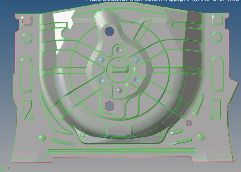
* In above image we can clearly observed that the extracted mid surdface is properly cleaned up and it's ready for shell meshing.
4. Meshing (2D):
* Before meshing we have to set the quality criteria file.
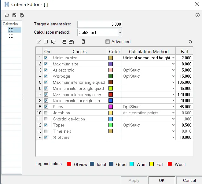
* This file is set by given quality criteria.
* After setting the quality criteria we mesh the given component with split method and do meshing surface by surface.
* We follow given instruction and remove the button surface.
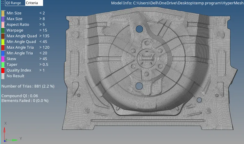
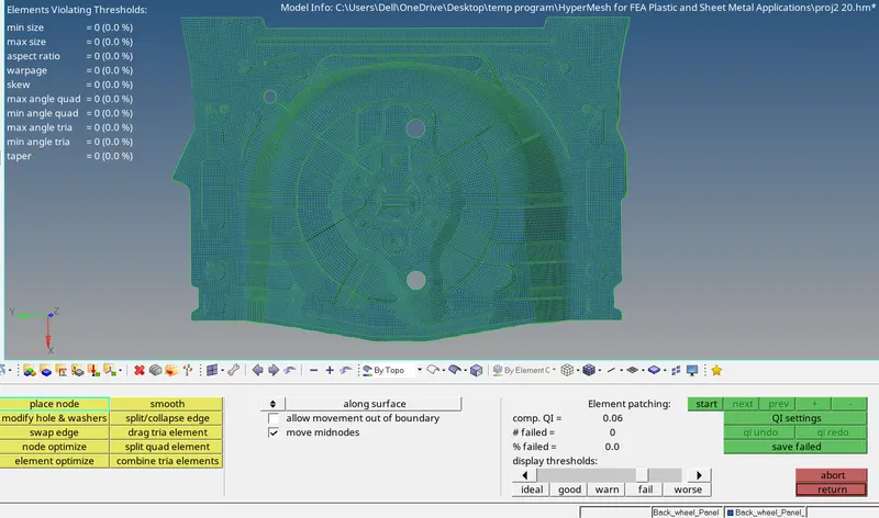
* For quality of element we done meshing and check the elements and if we observed elements which are failed in quality parameter such as warpage , aspect ratio , minimum and maximum length , skewness , taper , minimum and maximum angles of quad and tria ,etc. we have to pass the quality of such failed elements with the use of different tools such as quick edit tools , surface edit tools , translate , distance , rebuild mesh , remesh , smooth , quality index panel , replace nodes, element edit tool ,etc.
* We have to check duplicate in meshed model. for this we go to tool - check element - click on duplicates.
* So in this manner we done meshing of given component and pass all the elements for all given quality criteria.
5. Check Element Connectivity And Free Edges:
* For this we have to go tools - edges - select all elements.
* And then first we check element connectivity so we click on Preview equiv. If we found and disconnectivity between elements we click on equivalence and clear this problem and if we not solve from equivalence we have to fix this manually.
* After checking connectivity we go for checking free edges ( tools - edges - select all elements - click on find edges ) and if we find free edges we clear this by appropriate tools.
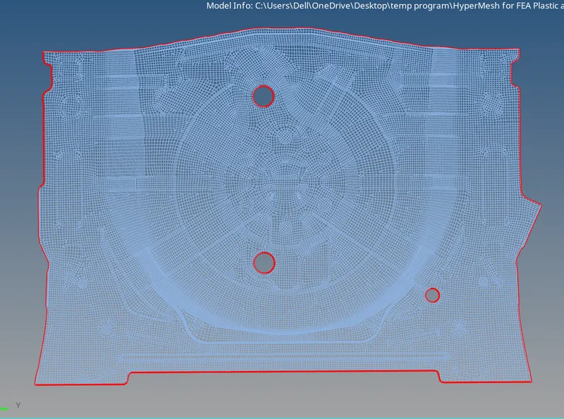
* In above image we can observe that there is no free edges between elements.
6. Check Elements Normals:
* In this process we check the direction of elements because during simulation if any external force applies it should sumulate in proper direction if normal of element is wrong it will not give proper results so this check is very important. for checking normal we go to tools - normals - display , it will shows elements in blue and red color if we fing some element which are opposite in normal then we correct its normals and make sure all element have same color in one plane.
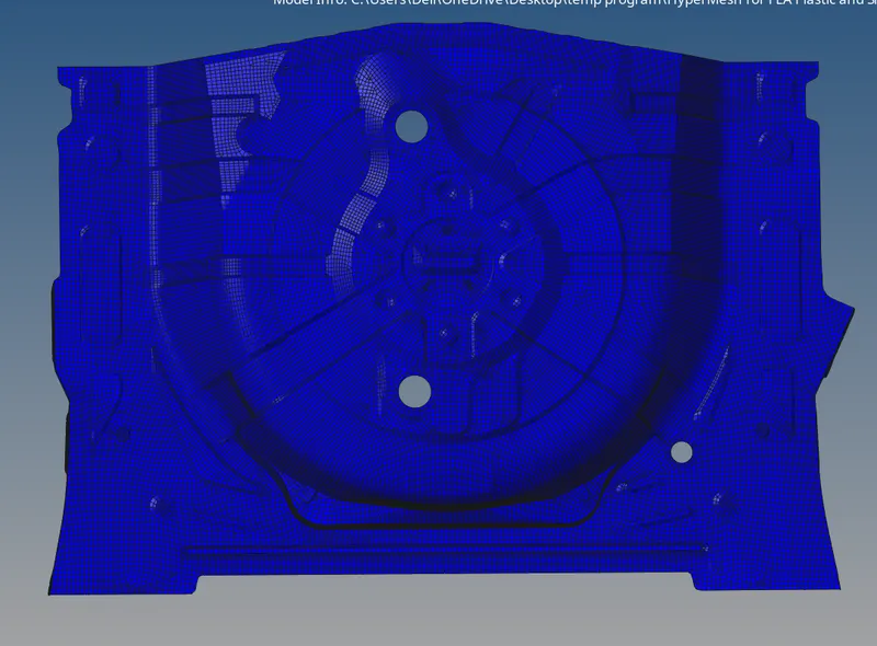
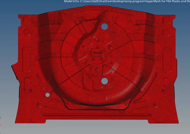
* As we can see that all elements normals are in one direction blue to red.
7. Assigning Thickness To Component:
* First we create the property and give the thickness value of our parent component.
* For measure thickness we go to geom - distance measure thicknesss between two points in geometry.
* After this we click on mesh component and click on assign and assign property.
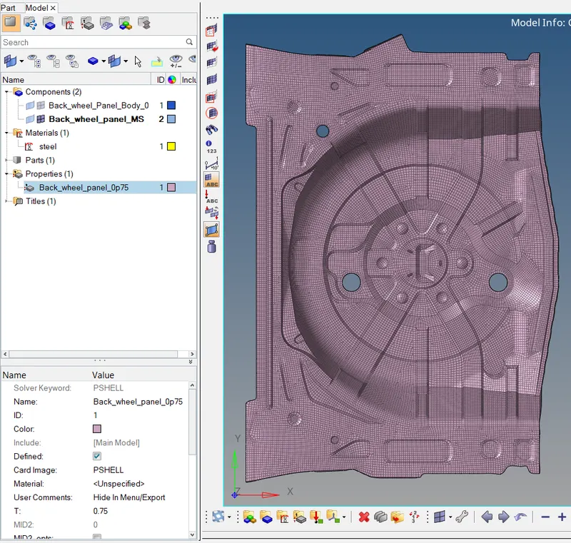
* In above image we can see that property with thickness value 0.76 is assign to our meshed model.
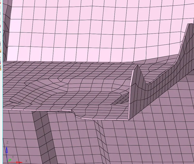
* Above image shown detailed 2D element representation of meshed model.
Final 2D meshed model of Rear wheel holder
* In below image the final meshed model is shown.
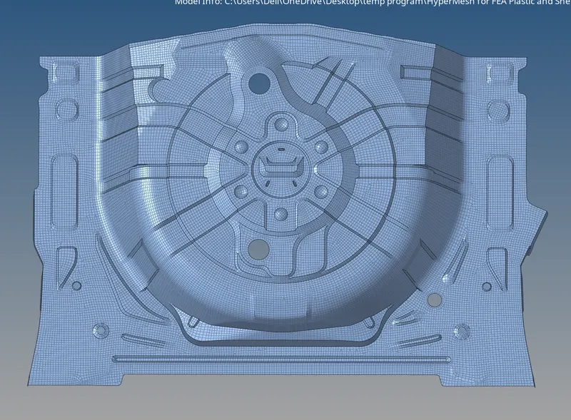
Result:- In this project we extract the midsurface ,mesh the model and assign the thickness. We learned how mesh sheet metal component.