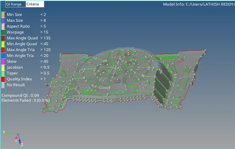
Week 12:Project 2-Meshing of Rear Wheel Holder challenge
AIM
- To mesh the given component under mentioned quality criteria and assign thickness to it.
PROCEDURE
- The given component is imported as .stp file format and the component is viewed by topo mode.
- The given component is checked for the uniformity in its thickness all over the geometry using distance option.
- The component is extracted for midsurface using the manual midsurface method by using the offset option in surface edit.
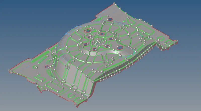
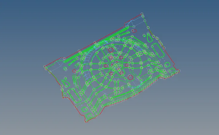
- The extracted midsurface is added in the new component section created and named as manual midsurafce in this component.
- After the extraction of the midsurface, the geometry cleanup is carried out by manual cleanup method using the toggle option in quick edit. On cleaning up the geometry the unwanted edges are toggled and if any new edges are required they are created using the split-surface-node or split-surface-line option.
- Using the automesh option in the 2D panel, the given component is meshed under the given target element size and the component is meshed following the quality criteria.

- The above given qualiity criteria are given as input in the check elements option in the tools section.On meshing the components are meshed with quads and trias and the mesh is made proper by following various processes.
- The mesh with the rotating quad elements are made proper by selecting the rotation quads along with the nearby elements and remeshing them using the automesh option.
- The elements are aligned in a line by aligning the nodes of the elements using the align node option in node edit.
- The meshed elements are frequently checked for satisfying the quality criteria by using the check elements option in which the warpage, skew, length etc are checked for failures in the elements.
- The failed elements are then saved using the save failed option and are retrieved, masked and reversed using the
mask option to display only the failed elements. 
- Then the adjacent elements to the failed elements are unmasked using the unmask adjacent and the optimizing process is carried out.
- The failure of elements on quality criteria are made proper by various methods depending on the element failure in the mesh. The various methods followed to remove the failed elements in the mesh are
- By using place node in qualiity index in which the node of an element can be moved to optimize the element.
- By using the element optimize option in quality index in which the element will be optimized based on the given quality criteria.
- By using the split & combine element in the edit element option in which a quad element can either be splitted into two trias or vice-versa.
- By using the smooth option in the 2D section, the elements can be selected and on performing this option the selected are made smoother by aligning the elements in a proper mesh flow with respect to the adjacent mesh flow.
- In case of any failure, translate option can also be used to fix the nodes of the element and the project option is used to place the misaligned nodes of the element over a surface edge.In case of any 2 opposite trias are found in the mesh, the 2 trias are made closer by using drag tria element in quality index and the trias are remeshed for removing them.
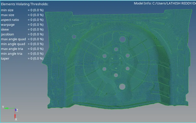
- After meshing the given component properly, the component given here is checked for symmetricity and as the given component here is symmetric the surfaces and the elements on either meshed side can easily mirrored on the other side using the reflect option in the tools panel.
- Before reflecting the surfaces & the elements, the component is checked for any free edges in between the meshed elements using the edges option in the tools panel and if any free edges are found they are removed by equivalencing the nodes of the elements in those respective edges.
- After that assign thickness for all components by create property and assign to it.
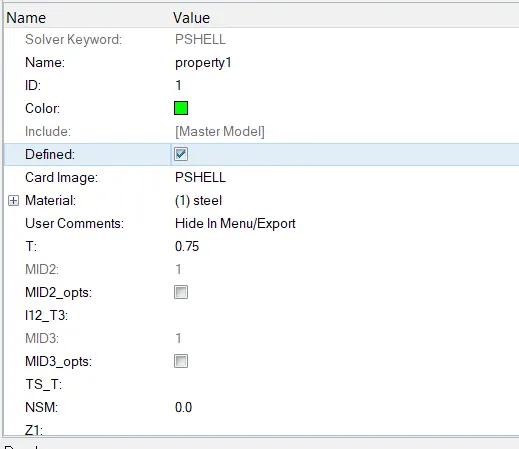
- Use distance option and measure thickness and create new selector and move the mesh to it by using organize option in tool panel.
And create property for that thickness and assign to that component.
CONCLUSION
- Thus the give component is mesh under given quality criteria and assigned thickness to it.