Week 12:Project 2-Meshing of Rear Wheel Holder challenge
OBJECTIVE
To mesh the given component with passing the quality criteria and also to assign thickness to all the elements.
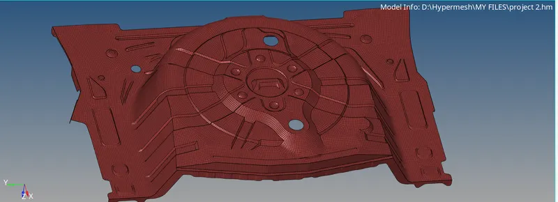
CAD MODEL IMAGE
PROCEDURE
The given component is a sheet metal and so we don’t need to take midsurface for every surfaces.
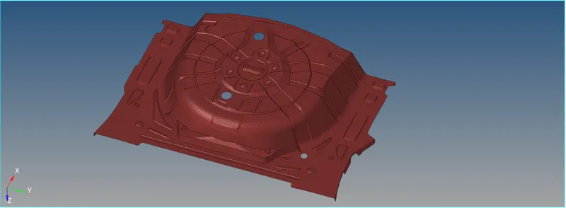
For this I tried to take mid with offset+planes+sweeps, and offset+planes. For this extraction options I can’t get an exact surface. The curves in the free edges aren’t captured properly. So, I took with offset only. Then I have a good midsurface like in this image.

Here we have some unnecessary lines in the surfaces so that we don’t need it. To get a better mesh and to pass the quality we have to toggle most of lines in the part.
Since this part is not a geometry so I try mesh this from the centre, because it’s a circular part. If it is another shape we have starts from any other side. So the thing is we have to better mesh flow all over the part.
the below image is after passing all the quality criteria.
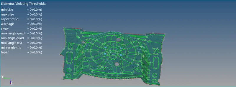
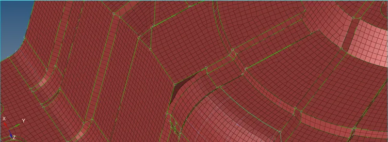
In this part most of the regions are in sharp triangular like corners, so they we can see some of the tria in the mesh in some case I try to smoothening with the nearest elements, in some regions I remesh without considering the construction lines to get a better mesh.
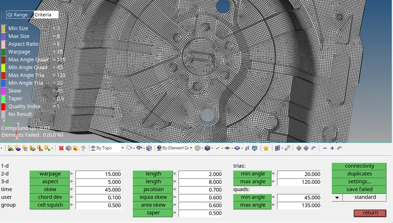
After meshing all the surfaces, we need to clear the quality issues.
Most areas are failing for warpage, skew and quality.
So trias should be very less concentrated in the surface.
Must solve opposite trias, rotating quads and stitching trias.
Mesh flow and density should be equal.
After finishing the quality issues we got a good mesh. And the we have to create a material and property for the elements.
Now we can compare the elements with the parent and 3d elements.
CONCLUSION
Meshing for this part is very easy because it’s a sheet metal and also no need to concentrate on the sharp edges. Finally the good 2d elements is achieved.
FINAL IMAGE