Week 12:Project-1-Meshing of Door Inner Panel Challenge
Week 12:Project-1-Meshing of Door Inner Panel Challenge
Aim:
Follow the Quality Criteria and mesh the following component and assign thickness:
Target Element Length = 4 Units
| S.N | Quality Criteria | Value |
| 1 | Aspect Ratio | 5 |
| 2 | Skewness | 45 |
| 3 | Warping | 15 |
| 4 | Taper | 0.5 |
| 5 | Min. Length | 2 Units |
| 6 | Max. Length | 6 Units |
| 7 | Min angle Quad | 45 |
| 8 | Max angle Quad | 135 |
| 9 | Min angle Tria | 20 |
| 10 | Max angle Tria | 120 |
| 10 | Tria % | 10 |
Important Points to Remember
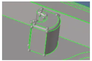
- The area which is having more than 6mm thickness should not model in 2D. You can capture them like in the Below-mentioned picture
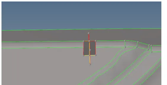
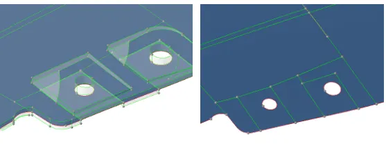
- The below image has some geometrical issue on it so modeling them in the 2D will be difficult.
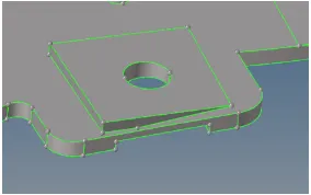
- In those areas, the main objective is to capture the hole so we can take a mid surface by creating a flat surface with a hole like an image below.
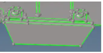
- No need to model the below-mentioned area. The mentioned area does not have a proper attachment to the model.
- For variable thickness areas, Assign the thickness taking an average value of the cross-section
Objective
The objective is to create a 2D mesh which meets the given quality criteria and to assign thickness to the parts of non-uniform thickness using Hypermesh.
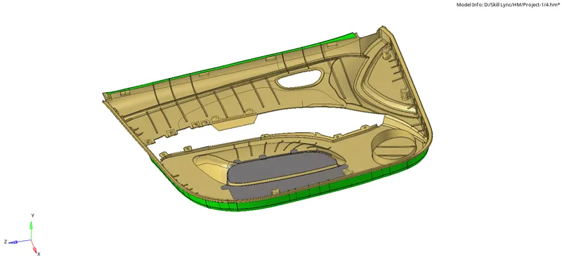
CAD Model Image
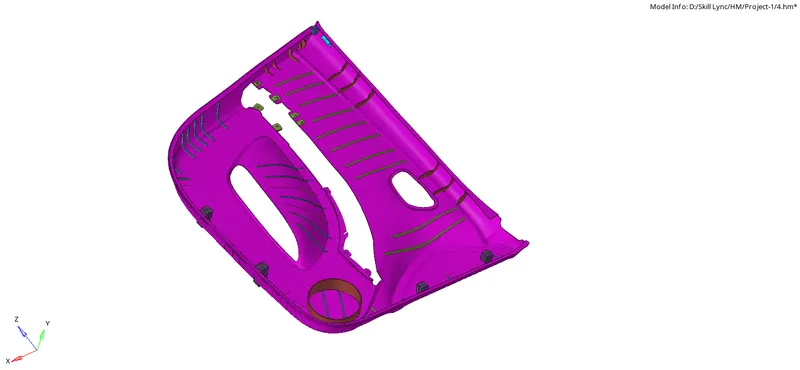
An image of the provided CAD model (door inner panel) is attached below.
Procedure
The procedure consisted of three primary steps which are,
- Extraction of Mid-surface from the CAD model
- Creation of a 2D shell mesh on the surface of the mid-surface
- Assigning a thickness property to the elements
- Checking for quality and continuity
i. Extraction of Mid-surface from the CAD model
A mid-surface was extracted from the provided CAD model since its thickness was very small compared to the span length of the component.
The method used to extract mid-surface w ere manual offset for the most part since the component had varying thickness. "Final edit tools" option was used for the ribs and also the manual method by using mid-line.
Base surface
The surface edit→→offset option was used to offset the surface on the top to the middle of the thickness by manually measuring the thickness and dividing it in half. The surface was then offset to this value.
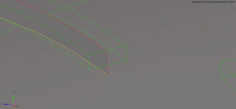
This method was continued for the entire base surface. They were later joined together using the surface edit→→extend option or by creating a new surface after projecting the line. The surfaces sticking out were deleted to create a continuous and accurate representation of the CAD model
Ribs and other features
To capture the doghouse, two perpendicular lines were made on its top surface and projected to the mid-surface. A new surface was created between the lines.
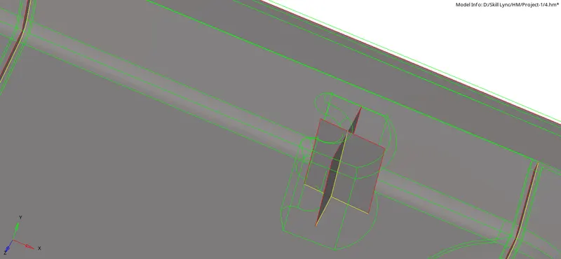
The fillets in the ribs were defeatured if their value was less than the target element length
Final edit tools option was used to create a mid-surface for the ribs automatically, to save time. In places where this option couldn't be used, lines→→Midline option was used to create a midline between two lines. This line was then projected onto the base and a new surface was created between the lines.
Extending the ribs and features onto the base surface
After all the features in the component were captured and mid-surface extracted, they were they extended onto the base surface.
ii. Creation of a 2D shell mesh on the surface of the mid-surface
- The mesh was created in the features and ribs initially and then on the flat surfaces.
- The 2D mesh was created manually using the 2D→→automesh with an element size of 4.
- The surface was divided into smaller portions by creating lines. This was done to ensure good mesh generation by the Hypermesh algorithm.
- Options such as mesh style, density were also tweaked to obtain the best possible mesh.
- The number of nodes were controlled to keep the tria concentration at a minimum.
- Cleanup tools such as drag tria element, combine tria element swap edge were used to ensure good flow of mesh. Manual re-meshing of the elements was done to decrease/increase the number of nodes to maintain flow and decrease trias.
iii. Assigning a thickness property to the elements
Mid-surface meshing is opted for a component where the geometry thickness is small when compared with the span length of the component.
- Therefore, mid-surface extraction is done and the thickness of the component was assigned to the elements as a property card.
- New property cards were created for the different thickness values.
- Within the components' database, several cards were created for components within a particular thickness range i.e. components having thickness between 2.1 - 2.5, 2.6 - 3.0, 3.1 - 3.5 and so on.
- After completing the mesh on the surface, the thickness of different components (ribs and structures) were measured using the Geom→→two points option.
- Based on the thickness of the component they were assigned to one of the component cards. This process was carried out until all the components were assigned to a component card. The thickness was the average value of the range.
- The component cards were assigned to their corresponding thickness property.
- The 2D detailed element representation view was used to check the if the thickness assigned corresponded with the actual thickness of the component.
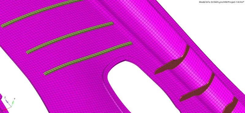
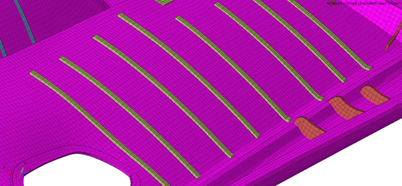
iv. Checking for quality and continuity
- The mesh was checked for quality within the 2D→→qualityindex→→QI settings. The failed elements are saved and later retrieved and masked to clean up failed elements.
- A more detailed check can be done using the Tool→→check elems option.
- The process was carried on until there were no failed elements.
- Tools→→edges option was used to check for continuity of the mesh. Any detached elements were stitched using either the equivalence option or manually using 2D→→replace.
- Since this particular part consisted of several rib connections, the T-connections were also checked. This ensures continuity of elements along the Non-manifold yellow edges. Duplicate elements were deleted and missing elements were created.
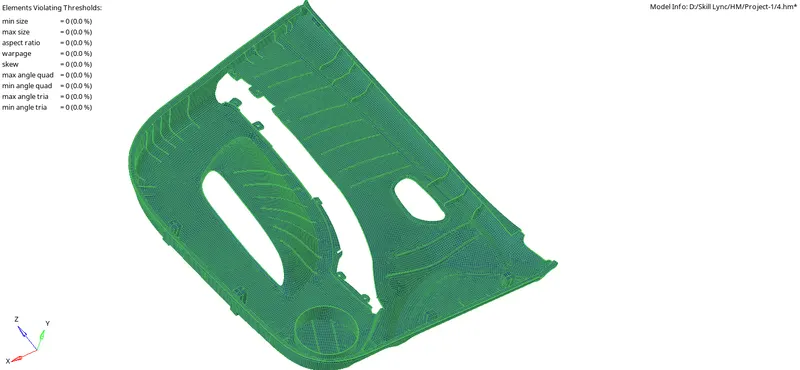
Final Model Image
- By Property
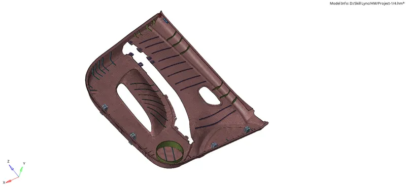
- By Component