Week 12:Project-1-Meshing of Door Inner Panel Challenge
To create the 2D meshing for the car side door panel by eliminating
geometric errors and considering the given elements quality criteria
using hypermesh.
MESH QUALITY CRITERIA :-
Target Element Length = 4 Units
| S.N | Quality Criteria | Value |
| 1 | Aspect Ratio | 5 |
| 2 | Skewness | 45 |
| 3 | Warping | 15 |
| 4 | Taper | 0.5 |
| 5 | Min. Length | 2 Units |
| 6 | Max. Length | 6 Units |
| 7 | Min angle Quad | 45 |
| 8 | Max angle Quad | 135 |
| 9 | Min angle Tria | 20 |
| 10 | Max angle Tria | 120 |
| 10 | Tria % | 10 |
CAD MODEL IMAGE :-
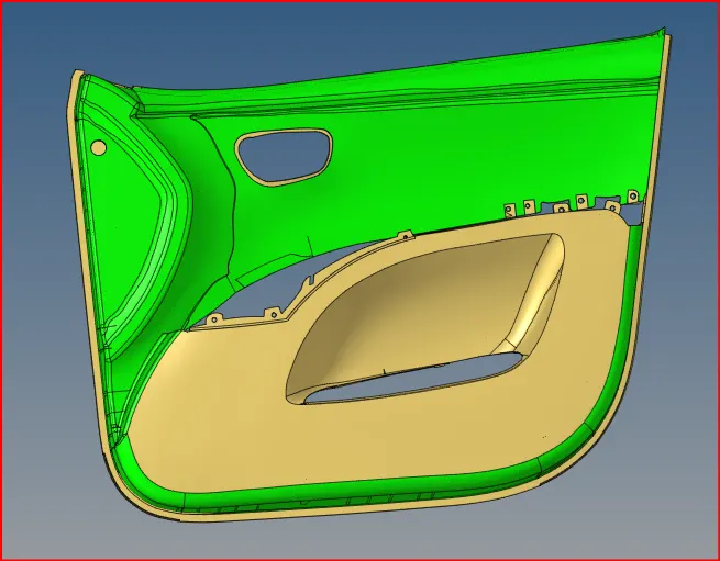
fig. cad model
The component is the inner portion of a car door which is usually made
of plastic.
PROCEDURE :-
After the model is imported, the component needs to be seperated into
multiple sub components considering the complexity of the component.
Different regions have different thickness so we can segregatebased on
thickness.
Certain regions like those shown in question picture can be ignored and
won't be meshed.
Further more , some ribs have thicknesses in excess of 5 mm. Such ribs
won't be midsurfaced and meshed.
Before proceeding, the component needs to be defeature of its fillets.
This can be done by accesing
Gometry > Defeature > Surface > Fillets.
And some time i used Create mid line and project this line on surface panel
and after that create surface.
Moving before midsurfacing we need to assign each region to seperate collector
using the Tool > Organize function.
Before moving, a new collector needs to be created to house the region that is
to be organized. This can be done in the component tree by right clicking and by
accessing Create > Component.
After assigning and seperating them into collectors, we can go ahead and extract
the midsurface on them one by one. There are two ways to extract the midsurface.
We could used the automidsurface option through Geometry > Midsurface but this
many not be ideal in most situations here.
Instead we can use the offset option in Geometry > Surface edit > Offset.
After creating the midsurface we need to attached the to each other as in every
case, the generated offset would be hovering. To do this we can extend the edges
that need to be attached to the corresponding surfaces using
Geometry > Surface Edit > Extend
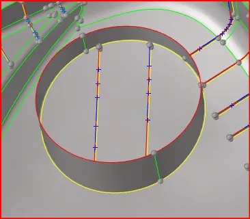
fig. cylinder using offset
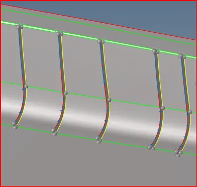
fig. ribs
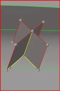
fig. houses
After the midsurface are generated, we need to carry out cleanup of the midsurfaces
to ensure the minimum length is achieved for all elements of the mesh. Also important
to prevent the formation of trais wherever possible by manipulating surface feature to
facilitate good quality mesh.
This is done by using various quick edit tools like the toggle, replace and split surface
node options. These tools can be accessed via Geometry > Quick > Edit.
Before we can begin meshing, we need to input the required mesh quality criteria through
Prefernces > Criteria File Settings. The mesh quality criteria is entered here.
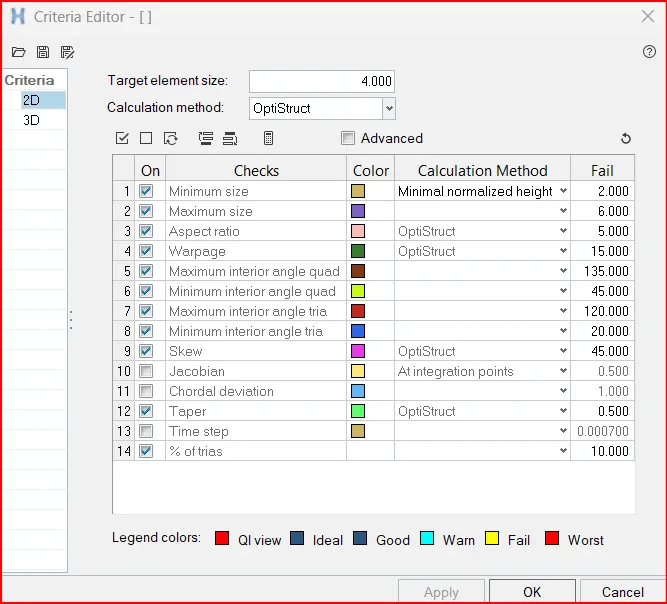
fig. quality criteria file
After that we can go ahead and mesh each sub component one by one,
ensuring meshes between connecting surfaces are equivalnced properly.
The target element length is 4mm. We can input this in the mesh option
at 2D > Automesh. Select the surfaces that are intended to be meshed
and click mesh.
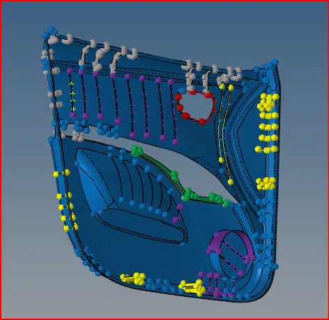
fig. Mesh whole part
After creating mesh we got some elements failing that time we solve the element failing
using like rebuild mesh and splitting the mesh and element cleanup.
After that assign the thickness of part.
FINAL IMAGE :-
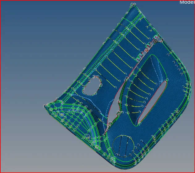
fig. final Part
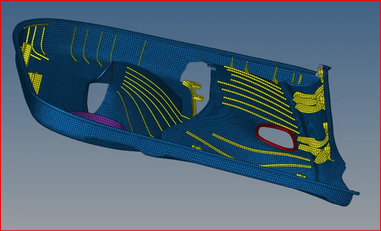
fig. after assigning thickness
CONCLUSION :-
The given side door panel was meshed as per given quality criteia. Due to
it being a plastic component, different regions having different thicknesses
was prevalent and the component was split into multiple sub component as a
result before meshing and they were assigned their respective thicknesses.