Week 12:Project-1-Meshing of Door Inner Panel Challenge
PROJECT -1: Meshing of Door Inner Panel Challenge
AIM:
To mesh the given side door inner panel by following the given quality criteria and assign thickness to the meshed model.
OBJECTIVE:
- Creating midsurface manually and doing geometry cleanup.
- To mesh and assign thickness to the complex plastic component.
- Learn quality checks and correcting failed elements by different methods.
THEORY:
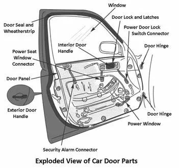
Door panels serve as an interface between the interior of the car and the inner workings of the door, and between vehicle occupants and the door.
They are expected to meet a variety of design specifications regarding safety, aesthetics, and functionality. In addition, they are expected to continue the material theme of the dashboard and pillars while concealing intricate electrical and mechanical components for operating locks, windows, and other features.
The door panel has evolved from a simple two-part system of latch and simple winding mechanism to a more sophisticated enclosure.
Doors currently have an inner full-width panel consisting of electronic windows, central locking system, and speakers. These panels typically consist of a foamed core covered with either textiles or plastics.
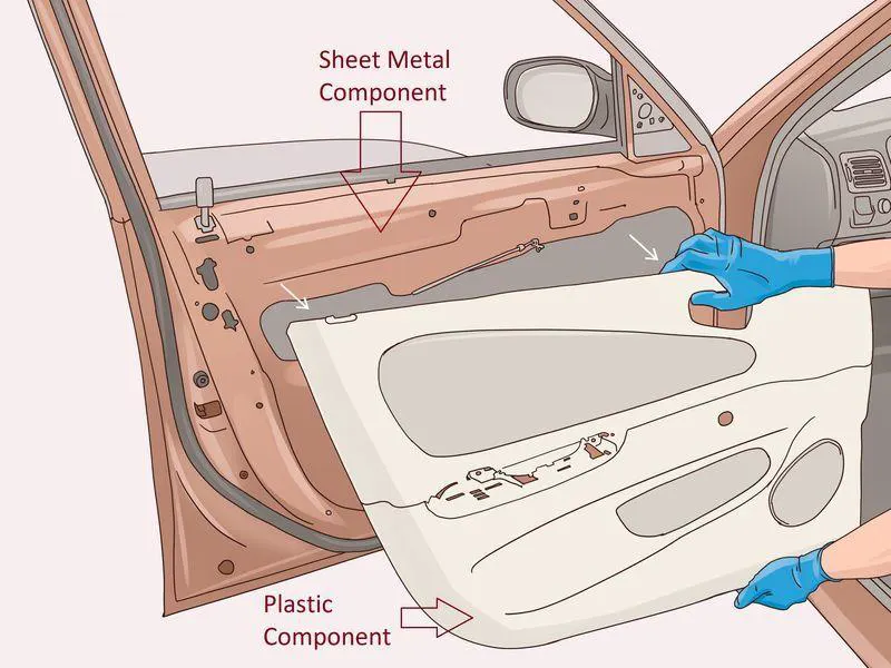
Door panels were formerly made of cardboard with an upholstered interior finish of vinyl, leather, cloth, carpet or other materials for the decorative trim. Modern cars typically have door cards made of plastic, most often using injection moulding as well as incorporating other decorative materials.
The design should incorporate both the necessary service amount and the functional unit. The door panel typically incorporates other parts that contribute to the appearance, functionality, and ergonomics of the vehicle. These include armrests, switches or other controls for windows and the locking mechanism, convenience lights, audio speakers, storage compartments, and other features.
In most cases, the door card is attached to the car's door frame by visible screws and ones hidden behind decorative plugs or under the armrest, as well as spring clips.
GIVEN CRITERIA:
Target Element Length = 4 Units
| S.N | Quality Criteria | Value |
| 1 | Aspect Ratio | 5 |
| 2 | Skewness | 45 |
| 3 | Warping | 15 |
| 4 | Taper | 0.5 |
| 5 | Min. Length | 2 Units |
| 6 | Max. Length | 6 Units |
| 7 | Min angle Quad | 45 |
| 8 | Max angle Quad | 135 |
| 9 | Min angle Tria | 20 |
| 10 | Max angle Tria | 120 |
| 10 | Tria % | 10 |
Component - Side Door Model
PROCEDURE:
Step - 1: Importing the model
- Import the given model into HyperWorks using the option File → Import → Import geometry → Choose the file → Import.
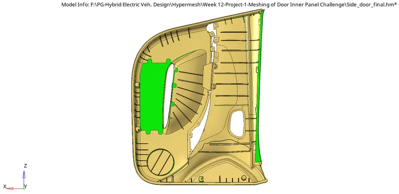
Figure : Imported model
Step - 2: Geometry clean up and topology
- The imported model is a complex geometry. It has many features like ribs, locators etc. Also, this is a plastic component. So, this component has different thickness on each feature. Here we perform geometry check and find out and correct defect such as collapsed faces, cracks, free edges etc.
- Once the model is imported, we check it in wireframe mode in 'By Topo' view to check for free edges. As this model is complex and not fully closed, the automatic midsurface may not work properly. So, we need to extract it manually.
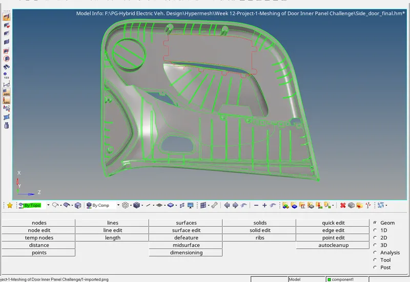
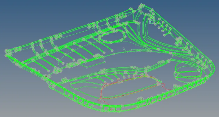
- The geometry defects can be corrected by using different tools such as replace, toggle edge, Ruled, spline etc.
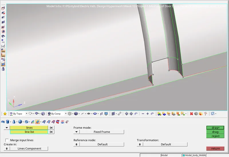
Surface creation using drag along a line tool
Step - 3: Defeaturing
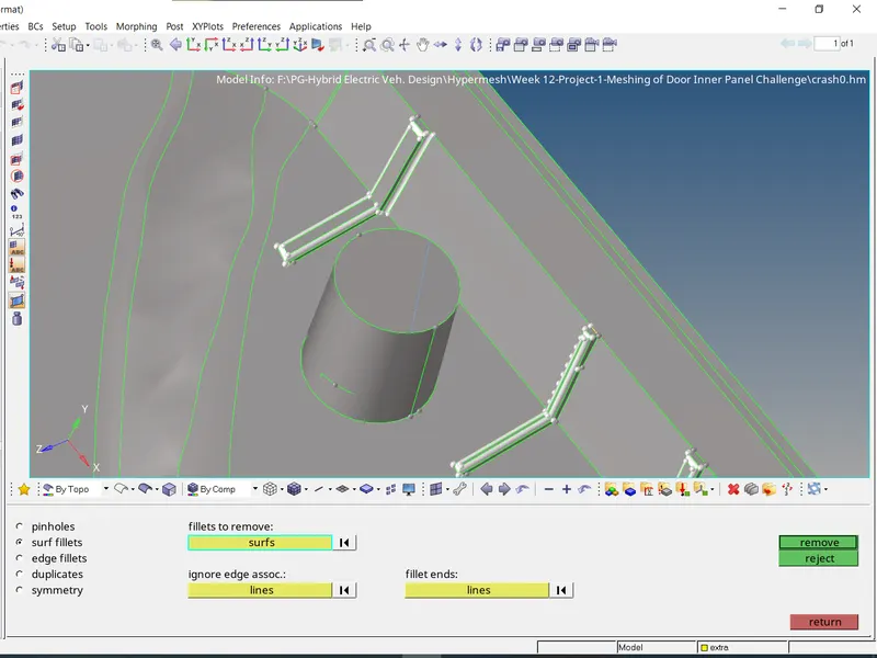
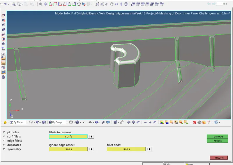
- We can use defeature option from geometry tools. Geom → Defeature → Surface fillet. Defeature the small fillets, where there are chances of element quality failure (That is less than minimum element size).
- But, some places the defeaturing may not work properly. So, we should correct it using other manual methods and tools.
- Use the Surf Fillets subpanel to identify and remove surface fillets. We can also select a fillet by picking one of the edges that it connects. Once found, fillets can be removed using tools that display automatically after the find process. By clicking on remove all selected fillets will be removed.
Step - 4: Midsurface generation
- Since, the given model is plastic and have complex structures, the auto-midsurface may not work properly as expected. So, we need to manually extract the midsurface. One method is to extract the whole surface by using offset method in 'surface edit' panel.
In other way, we can use both auto-midsurface and offset tool. The midsurface of parts which are not created by auto-midsurface tool can be produced by using offset tool in surface edit. - The midsurface of base (main part) can be created by using 'sweep' option in auto-midsurface. All other parts can be created by using offset tool. Some of the ribs can be created by using other auto-midsurfacing option.
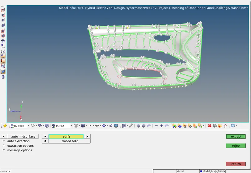
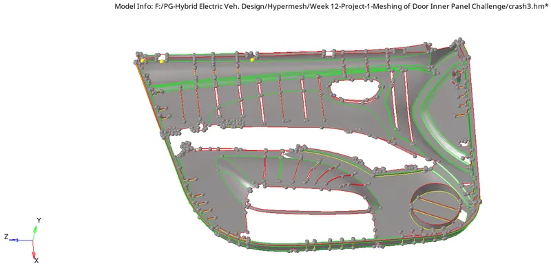
Midsurface created by auto-midsurface - In the above shown midsurface(Created by auto-midsurface), have some defects and missing parts. These regions can be edited by using edge edit, ruled, quick edit etc.
- All missing parts can be created by using, 'offset' option from 'surface edit'.
Before offsetting any component, we need to check for thickness of entities and measure. Geom. → distance. We can find different thickness. For the parent base, the thickness is 2.8 units. - Select, Geom. → surface edit → offset, Offset moves the selected surfaces without retaining their connections to surrounding geometry. Select the surface we need to offset and duplicate it before offsetting. Input the offset value as half of the thickness. Always remember to check the vector normal, so that we can understand the offset direction.
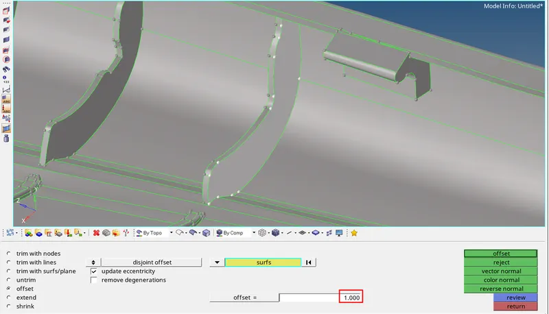
- The offset surface should connected with base midsurface with proper connection. We can use replace edge, node replace, toggle edge tools for making connection with the midsurface.
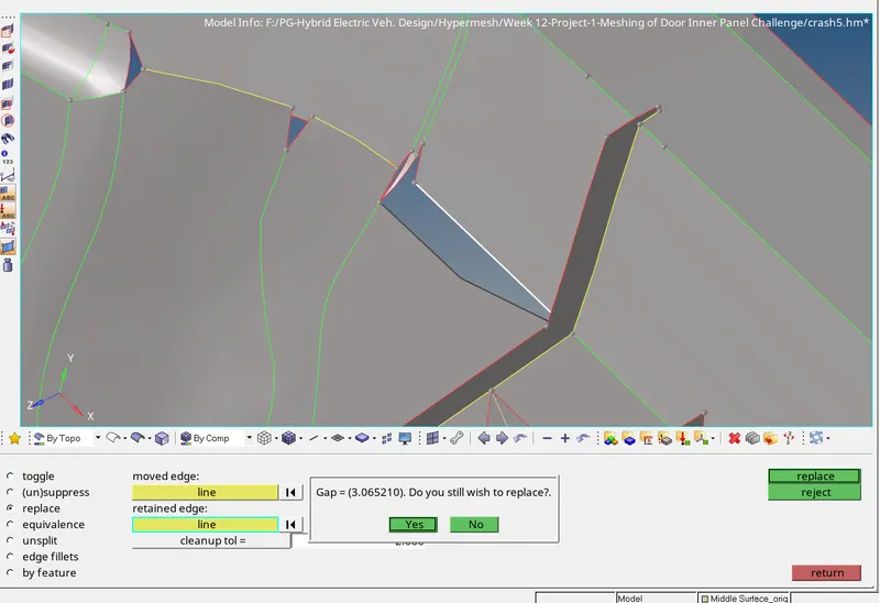
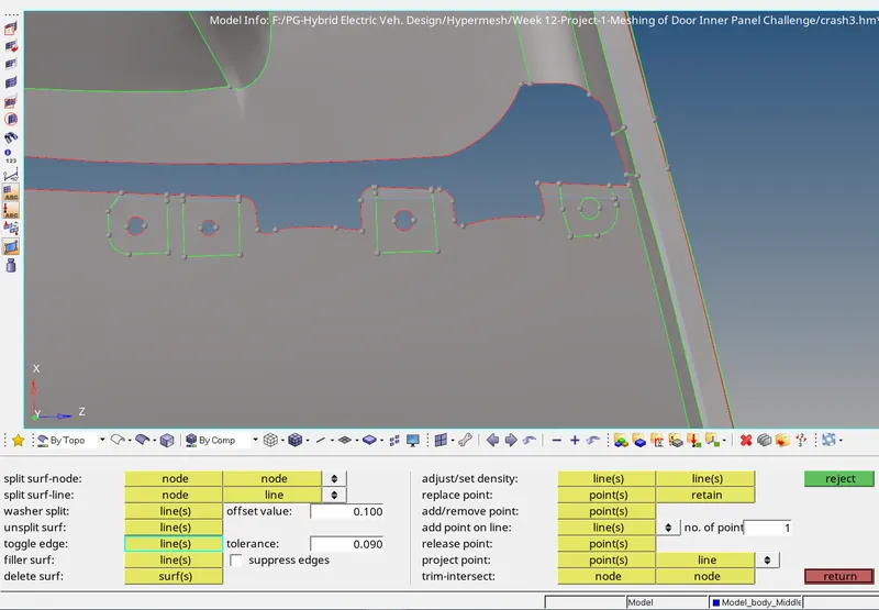
- The areas like the below image are captured as shown in figure.
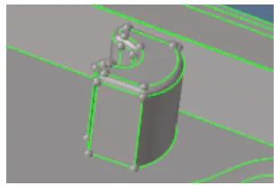
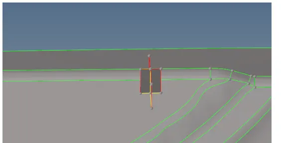
- We can capture the symmetrical component's midsurface using final edit tool.
Geom. → Midsurface → Final edit tools → Select opposite surface 1 and 2 (Those surfaces in-between the midsurface is needed) → Extract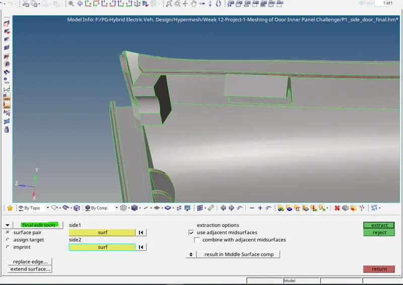
- After extracting the whole midsurface, check for any defects. As this is a complex geometry, the autocleanup may not work properly. So do it manually. Use toggle edge, replace options as well.
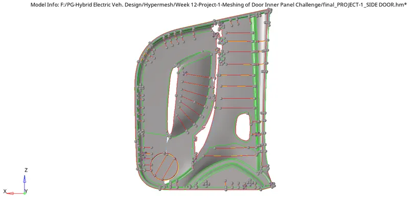
Final midsurface extracted
Step - 5: Meshing
- Once the midsurface is extracted, we can start the meshing as per quality criteria given. So initially we need to save the quality criteria and parameter file as per requirement.
Preferences → criteria file settings and parameter file settings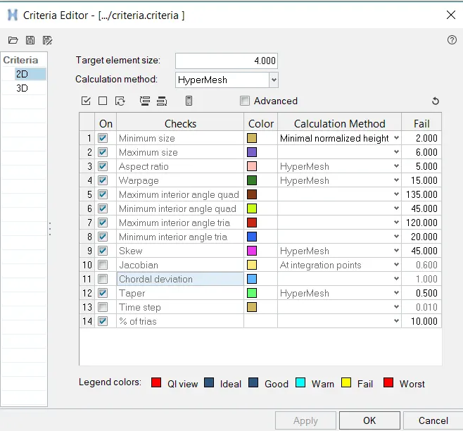
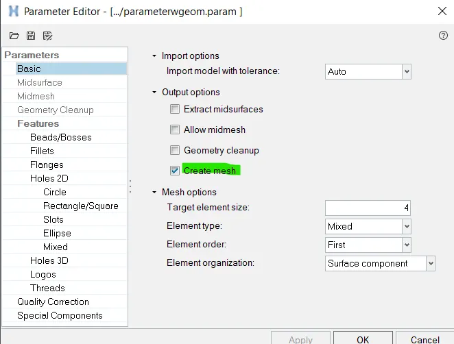
- While saving the parameter file, save the parameter file by unticking the geometry cleanup. The automatic geometry cleanup may distort the midsurface. That is why we have done it manually.
- For meshing, we can approach in different method; Batch meshing or automeshing manualy by part by part. Since this is a complex geometry the batchmesh may not give proper mesh quality. So, after batchmeshing we need to rebuild the mesh quality and flow.
- For batchmeshing, follow; 2D → automesh → Batchmesh/QI optimize → select criteria as well as parameter file saved or specified → Select surface → mesh.
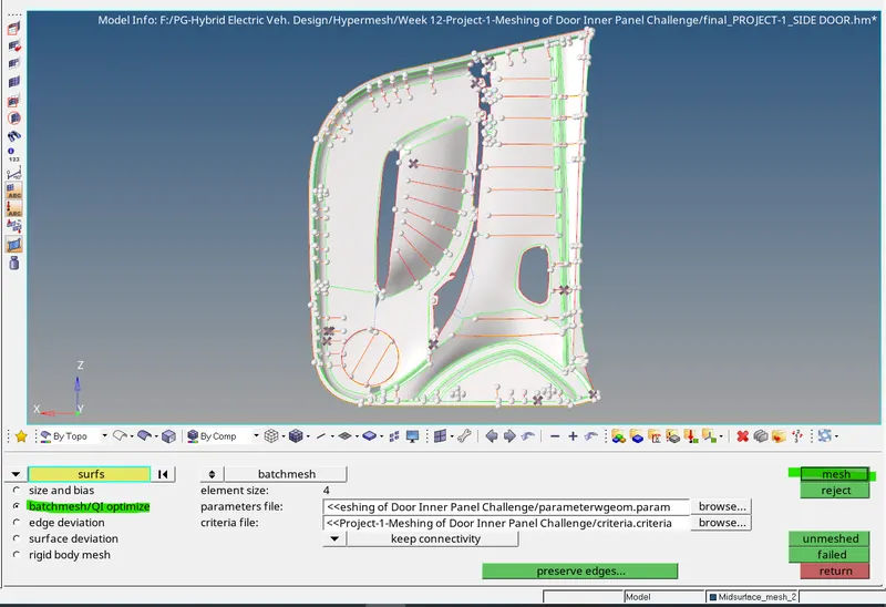
- Check the mesh created and use 'rebuild' tool at required region. Correct the mesh flow. Try to avoid back-to-back tria, tria touching each other, rotating quads and trias at free edge. Use rebuild, element edit, replace, drag tria tools for that purpose.
Step - 6: Mesh quality check
- Once after completing the mesh we need to check and ensure that the mesh so generated is as per the given quality criteria.
- For this we use the option 2D → qualityindex as well as Tool → check elems. There might be deviations in some or all of the quality criteria which we need to correct by using the various options available in the cleanup tool options available in the qualityindex. Also, we can use element edit, replace node options as well for correcting failing elements.
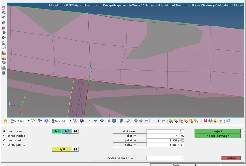
Distance tool used for correcting failing element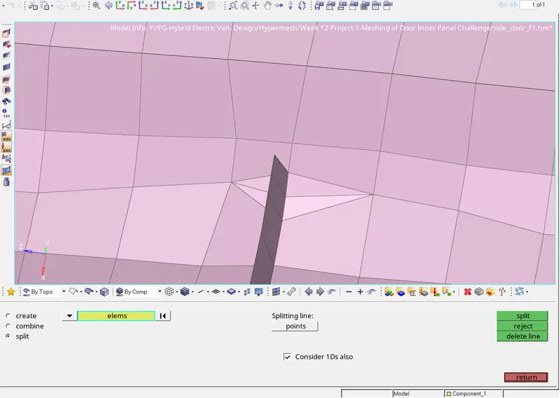
Element edit tool for splitting element and combining them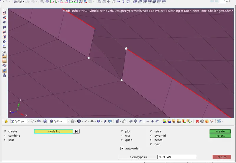
Element edit tool for creating an element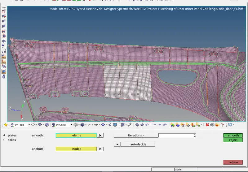
Smooth tool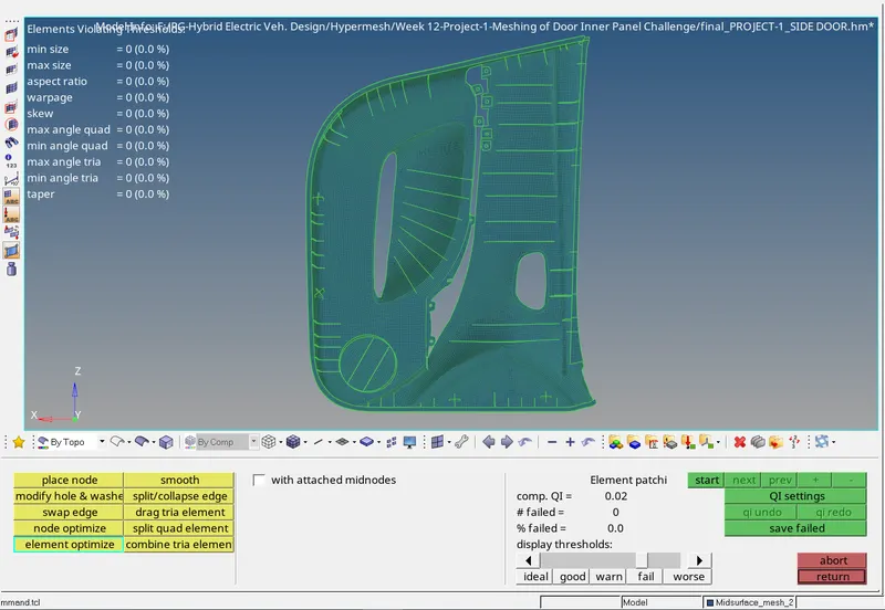
Quality index and different tools
(Note: If we are adding any lines nodes or creating T connection to the meshed surface, it will distort the mesh created. To avoid this use, disassociate option from topology revision; Preferences → topology revision option → select 2D mesh as disassociate. But this operation may result in disconnection of elements. So, use replace node option to make connection and perform 'rebuild tool' on those areas to get a better meshing.)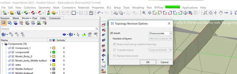
Step - 7: Model check
- Check for edges: The components are checked for edges.
Tools → edges → select element dispalyed → find edges,
If no error noticed, delete edges. select element again → preview equivalent → return
otherwise, you can click on equivalence and try to fill that. we can also use replace node option.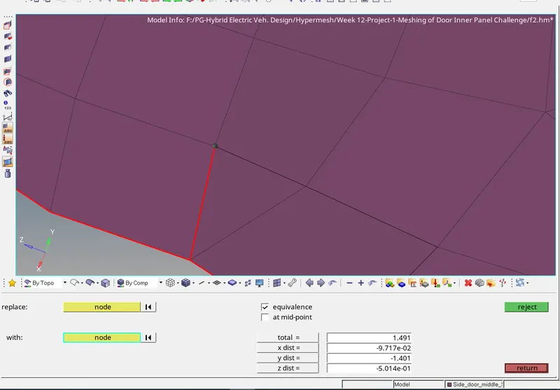
Using replace tool for making connection
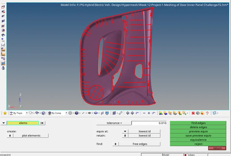
Edge check - Check for Normal: The normal direction is checked by following the below steps,
Tools → Normals → display → we can choose color display or vector display.
The defected element's normals are reversed using the same tool by selecting the element.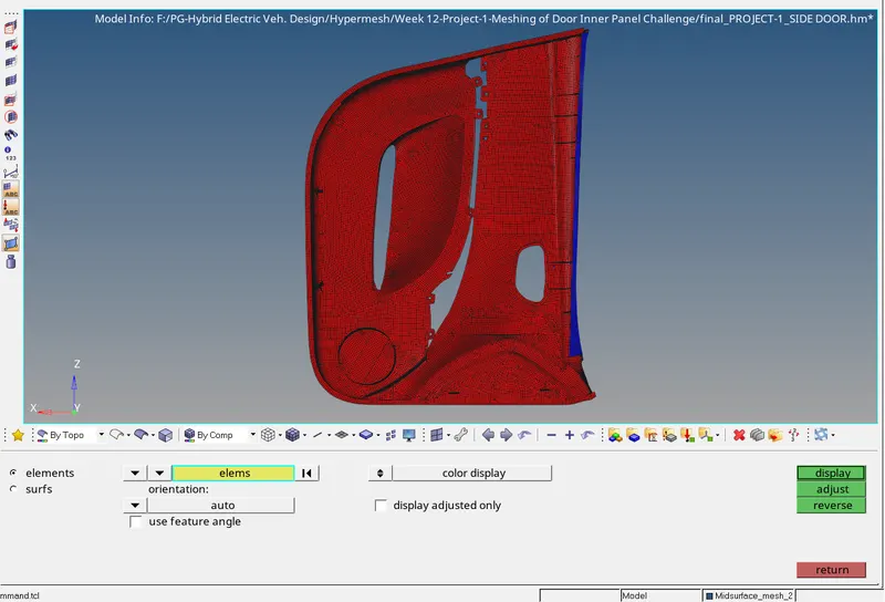
- Element to surface check: To check how the element is captured the surface geometry.
mesh → check → elements → comparison → click on element tab shown in source entity → Select element displayed → Proceeds → click surface tab in the target entity → select surface displayed → Tolerance = 0.2 → Run
The yellow and pink color in mesh is okay. If there is defect, we used project tool to rectify it.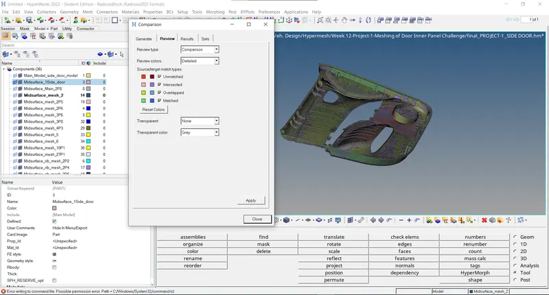
Step - 8: Assigning thickness
- Thickness checking: View the parent model and check the thickness in every region and then assign a thickness by creating a collector component and organize the mesh into it. The distance tool is used for measuring thickness. For variable thickness areas, Assign the thickness taking an average value of the cross-section.
- Create a new component tab for various region having different thickness and rename them with adding thickness value.
Right click on browser → Create → Component.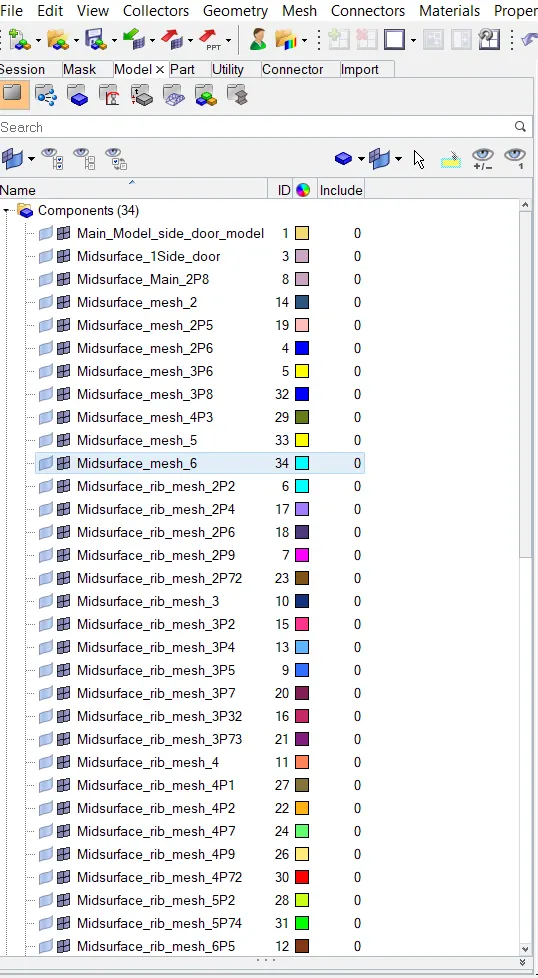
Component tabs created - We can use collectors to organize the entities as per thickness to the newly created component tab.
Tools → organize → Collectors → Select element and the destination component → move.
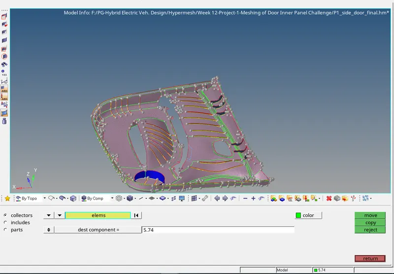
Using organize tool - Assigning property: First, we need to create property tab. Right click on browser → Create → Property.
After creating a property rename and add thickness value to it.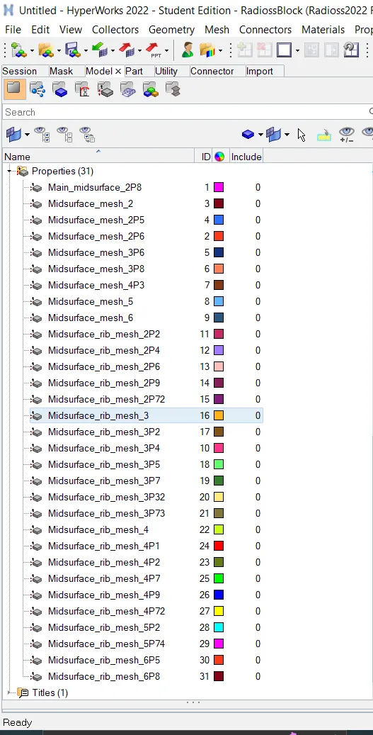
Property tabs created - Then for assigning this property to each component, follow this step; Right click on component tab → Assign → select the property tab we created according to the thickness → ok.
-
Now Switch to the 2D Detailed Element Representation to check whether the thickness was applied to every region or not.
FINAL MODEL:
- QUALITY CHECK:
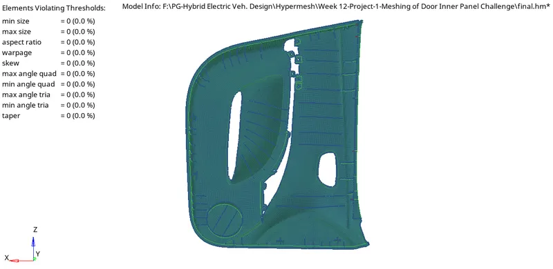
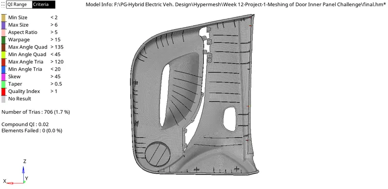
- FINAL MESHED MODEL:
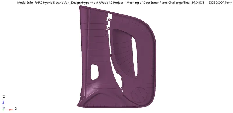
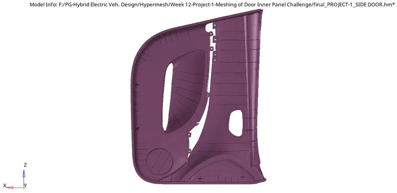
RESULT:
The given side door model has been meshed as per the given quality criteria and the thickness is assigned. The meshing results only 1.7 % trias. Almost all features have been captured.
CONCLUSION:
This project helps us to learn meshing on complex structures and how the midsurface is extracted manually for such geometries. It also allows us to work with different tools in hypermesh for extracting midsurface, quality correction, meshing etc.