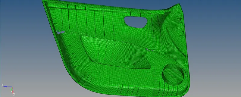
Week 12:Project-1-Meshing of Door Inner Panel Challenge
Aim:
To create a 2D mesh on the side door plastic component according to the quality criteria and apply the thickness to the mesh.
Solution:
The given component is a plastic component which is a side door model. These types of plastic components have varying thicknesses and are having a large number of fillets and ribs inside the model.
1. The First step in 2D meshing is to open the software and select a solver. We select Optistruct as a solver. Next, we import the IGES file.
For that select the IMPORT file icon > Then choose the Side door file from the directory > Then click on import. Then the Side door model will appear on the screen.
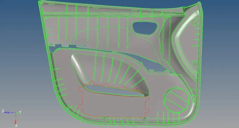
Fig. 1 Imported CAD model of the side door
2. We need to clean up the geometry. Some free surfaces, surface duplication, some glitches in the surface, etc. may be present. To remove all these issues before meshing we need to go for the topology clean-up.
3. We can use the visualization option to see the free edges and surface duplications. For that uncheck all the green lines which are of shared edges in the visualization option and then switch the model into the wireframe mode. Then we see the duplication of surfaces and free edges. If there are free edges in the geometry except at holes and outer boundaries, Then that is the indication of missing surfaces and improper connectivity.
4. If there is no T connection and still there are yellow lines present, then it is the indication that there are duplicates of surfaces. Hence we need to delete the duplicate surfaces and for removing the free edges which are red lines, if present we can use the EQUIVALENCE option in edge edit, TOGGLE option in quick edit can also be used, If these two can't solve the problem we can make use of spline and ruled surface options in the SURFACE panel. We can also use the replace point option in the quick edit tab.
5. After the geometry cleanup we need to take the mid surface of the model. Since this is having the Third dimension which is of less magnitude. We can take the midsurface and mesh it in 2D and then add thickness to the mesh which is exactly the same as the model.
6. Then we need to go for the geometry check or clean up, in that process we need to pay attention to our target element size, minimum element size, and maximum element size. We need to defeature the fillets which have a possibility of elements failing for minimum size. Ask CAD Design engineers about the importance of those fillets. If those fillets are not that important then it is permitted to defeature the fillets. For defeature go to geometry tab > defeature> surface fillets> select the fillets we need to defeature>remove. To remove PINHOLES Go to the geometry tab>DEAFEATURE>PINHOLES>select the pinholes> REMOVE. Then the pinholes will be removed.
7. To take midsurface of the fillets, first measure the thickness of the fillet. This can be done using the DISTANCE option by pressing F4. Then place the radio button at two points. Then choose the two points at the extremum on opposite sides to find the thickness of the fillet. Then create a new collector named MIDSURFACE and make it the current component. Then measure the side door body thickness by pressing the F4 button.
8. Navigate to GEOMETRY>SURFACE EDIT>OFFSET(or use the shortcut shift+F9)>select the outer surfaces off the body>choose duplicate to current component>click on vector normal and see whether the offsetting is in the right direction, if not then click on reverse normal>Then type in the offset distance as half of the thickness>Press offset.
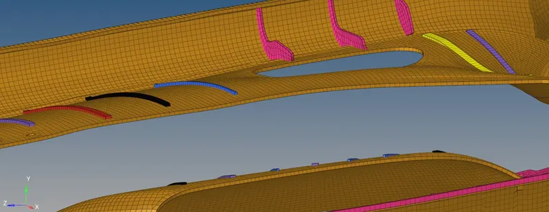
Similarly, each and every fillet and rib is also midsurfaced to the midsurface collector.
We can use the Drag the line option to drag the surface through the lower body part of the side door. For that go to GEOMETRY>SURFACES>DRAG LINE>SELECT THE LINE OF FILLET WE NEED TO DRAG THROUGH THE SIDE DOOR>TYPE in the distance to drag as some value so that the surface made by the line cuts the surface of a side door. Then we need to remove the additional protruding surface of the fillet midsurface from the side door. We can use the TRIM WITH SURFACES/PLANES option for that. Go to GEOMETRY panel>SURFACES EDIT>place the radio button in trim with surfaces /planes>then select the surfaces we need to trim(Here it is the protruding surface of the fillet and the side door surface)>Then hit TRIM. Then the protruding surface can be deleted by using the delete option by pressing F2. This process should be done for each and every fillet and rib so that the meshing will be done with proper connection with the side door and fillets and ribs.
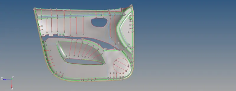
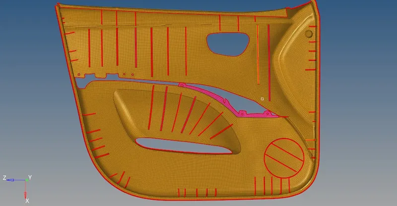
Fig. 2 midsurface of the side door (front view)
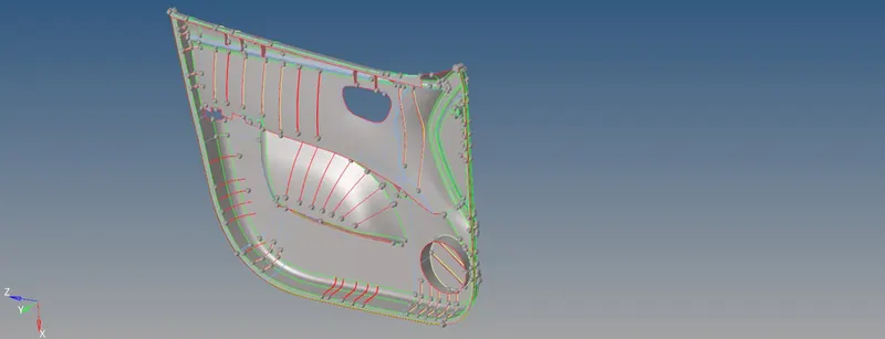
Fig. 3 Midsurface in a different orientation
If the T connection cannot be made using the TRIM with surfaces option, we can simply mesh the fillet midsurface and the side door separately. And then PROJECT the nodes of the fillets to the side door surface. This can be done using the project option. For this Go to the TOOL panel>select PROJECT>Place the radio button into the surface >Select the lower nodes of the fillets>Turn on the midsurface of the side door>select the surface to which we need to project the nodes>Hit project.
This will project the nodes of fillets to the surface but then also the connectivity between the mesh in the fillets and the side door are not proper. There we can solve this issue by using REPLACE NODE option. HIT F3 replace nodes of fillets with that of side door will ensure proper connectivity of the meshes. Then we use the SMOOTH option to smooth the mesh. For that press SHIFT, +F12>Select the elements we need to smooth>Hit smooth until require smoothing is obtained.
Then we can start meshing the midsurface. there we can use the automesh option in the 2d panel to mesh the surface.
Go to 2D PANEL> AUTOMESH>Select the surfaces needed to mesh>give the element size as 4 mm > HIT MESH
Then the whole surface got meshed with the radio button in density, we can clean and change the nodal densities at various locations so as to get a smooth mesh with a lower number of trias. Before accepting the mesh we should change the densities in such a way that the maximum trias removal is possible. Then accept the mesh. Various things to keep in mind in meshing
- If there are any opposite trias, we should re-mesh these trias, and thereby we can remove those trias.
- There should not be any mesh transition at the fillet regions.
- A smoothing command can be used to smoothen the mesh. For that go to the TOOL panel >click on SMOOTH> Select the elements needed to smooth>Click on smooth until we get an even mesh flow.
- Never place TRIA elements at the edges or inside the washer.
- Adjacent TRIAS must be removed. For that, we can use the DRAG TRIA option in the QUALITY INDEX tab in the 2D panel. We can select the tria and drag it to any other position so that we can remove the adjacent trias.
- Rotating Quads are not acceptable in CRASH TEST but acceptable in structural analysis. Same directional following TRIA elements are acceptable in CRASH ANALYSIS but not permissible in structural analysis.
- Always mesh the component keeping in mind the quality requirements.
Then we check the connectivity of the elements in the mesh. For that, we should check whether there are any free edges present in between elements. For that Go to TOOL panel>FIND >choose FIND EDGES. this will show the free edges in between the elements. To equivalence, those free edges, Go to TOOL panel>FIND >choose FIND EDGES>select the elements in between which the free edges are present > PREVIEW EQUIVALENCE>EQUIVALENCE. This will ensure there are no free edges in between elements.
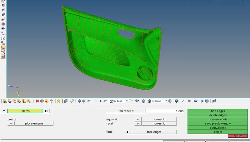
Fig. 4 2D mesh after equivalencing the free edges
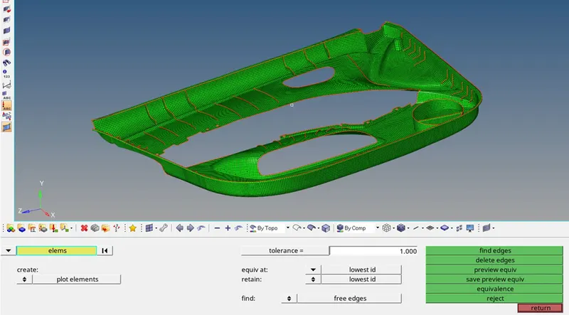
Fig. 5 2D mesh after equivalencing the free edges (in other orientation)
Then we need to check for quality criteria. The quality requirements are given below and the target element size is 4 mm.
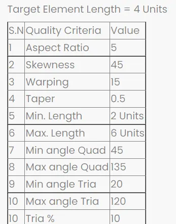
Fig. 6 quality criteria
After meshing some of the elements violates the quality criteria. This can be checked by Press F10 which is the check element tab. This can also be entered with Tool>check elements>type the quality relevant boxes. Then click on the respective options to check whether tab elements fail or not. So we should make them follow the quality criteria. For that the tools used are
1) Replace the node option. For that PRESS F3, they replace the nodes with each other.
2) Go to QUALITY INDEX then use ELEMENT OPTIMISE, this is used to optimize the elements based on the criteria we typed in the criteria file settings in the preferences option in the menu bar. Go to PREFERANCES> criteria file setting> edit the Table as the quality criteria> then use element optimize and click on near the element we need to optimize.
3) Also we can use the place node option in clean-up tools in the quality index. We can move the node along the surface /Normal to surface to optimize the element.
4) Also smooth tool in the TOOL panel also can be used.
5) In case an element needs to split, Then we can make of split element feature. For that press F6 place the radio button in the split and select the elements we need to split, then click the points through which we need to split the elements. Then click Split. Then the elements will get split.
6) PRESS F5 which is the mask option so we can save the elements from the check elements tab and then we can retrieve those elements using the mask option, we can work on those failed elements without disturbing the other quality elements.
7) TRANSLATE option can be used to solve the element failing issue. For this first switch to element quality mode and find out the failed nodes. And press SHIFT+F4, so that TRANSLATE OPTION appears. Then Choose the node And select the nodes in giving the direction of movement of the node. This option if used in a logical way can solve many element failing situations.
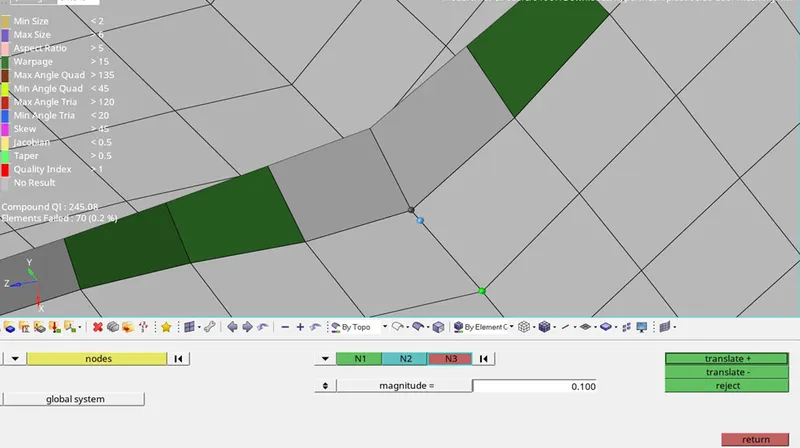
Fig. 7 use of the translate option to optimize the failed elements
Go to TOOL>ORGANISE>select the elements of the surface having the same thicknesses>Choose the destination component as a collector of appropriate thickness >Hit MOVE. Similarly, every newly created collector must be occupied with the elements which require the appropriate thickness as stated in its collector name.
Then right click on the collector >ASSIGN>choose property>choose property having thickness same as indicated in collector name>Then apply>OK. Similarly, every collector must be applied with its appropriate property of appropriate thickness.
Go to 2D detailed representation will show as the mesh having thickness exactly same as that of the actual component.
Fig. 8 screen snip of collector and properties created
RESULT: