Week 12:Project-1-Meshing of Door Inner Panel Challenge
AIM: Follow the Quality Criteria and mesh the following component and assign thickness:
Target Element Length = 4 Units
|
S.N |
Quality Criteria |
Value |
|
1 |
Aspect Ratio |
5 |
|
2 |
Skewness |
45 |
|
3 |
Warping |
15 |
|
4 |
Taper |
0.5 |
|
5 |
Min. Length |
2 Units |
|
6 |
Max. Length |
6 Units |
|
7 |
Min angle Quad |
45 |
|
8 |
Max angle Quad |
135 |
|
9 |
Min angle Tria |
20 |
|
10 |
Max angle Tria |
120 |
|
10 |
Tria % |
10 |
About project
Door panels are expected to meet one of the toughest sets of requirements and door panel assemblies reduce the need for other energy-absorbing materials, resulting in cost reduction for manufacturers due to simplification of door construction. Currently honeycomb-based plastics are widely preferred due to their tougher, lighter, and better acoustic properties.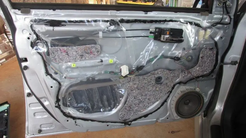
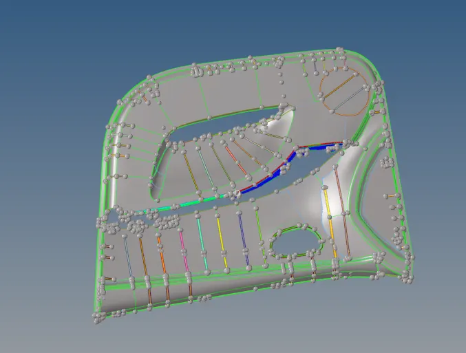
CAD GEOMETRY
PROCEDURE :
1. The cad geometry is imported
2. Checking the thickness of the cad model where ever needed.
The base part (most common) was having a thickness of 2.5 mm
3. The midsurface is to be created for shell meshing. For mid surface, i used the outer panel as it was clear and having less number of features.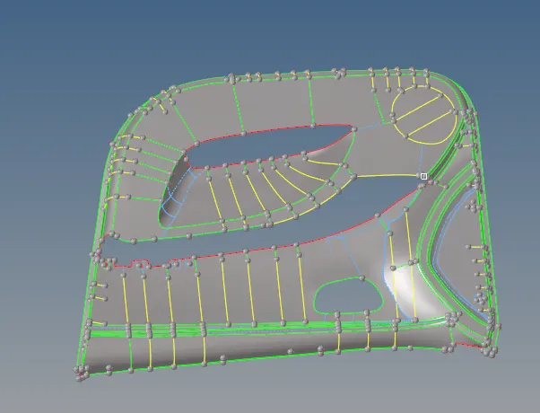
then projected the features ( ribs, Cyindrical features etc. ) on the plane base plate.
As it is a plastic component,thickness varies, so need to measure the distance of different surfaces and offset as per it.
To create the midsurface for ribs use the lines> midline option and create and project it to the mid surface and then trim the surface; then creating a surface between them.
Grouping those in different components. (create>component)
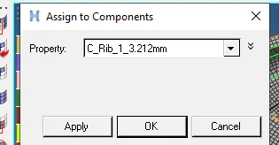
Assigning property card by their thickness. (create>property)
Meshing of the components on the required mesh size/quality.
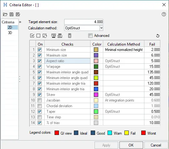
After meshing the components; rebuilt the mesh for better mesh flow and quality
reduced some of the curcular nodes to 4 nodes and rotated them according to the requirement. 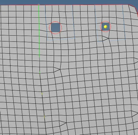
checking elements failing for quality; and correcting them making zero element failure.
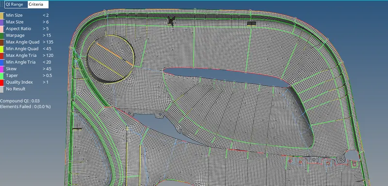
then after assigning the property card to the components
to view the thickness of the mesh used 2d detailed representation of the mesh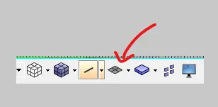
after giving the 2d detailed representation we get 3d view of the coponents (with thickness)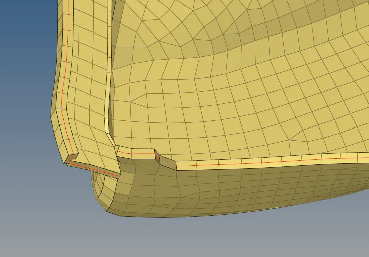
after meshing the final output was: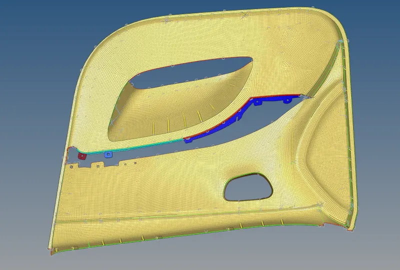
Conclusion :
The component was midsurfaced;midsurfacing of Doghouse components, ribs etc.
meshed as per the quality criteria and correcting them
property assigned to respective components and 2d deatiled representation.
Thanks
Vishal.