Week 12:Project-1-Meshing of Door Inner Panel Challenge
Obejctive:
To Extract the midsurface of the given component and to mesh then assign thickness to it with a target element length of 4mm and the rest of the quality criteria as follows:
| S.No | Quality Criteria | Value |
| 1 | Aspect Ratio | 5 |
| 2 | Skewness | 45 |
| 3 | Warping | 15 |
| 4 | Taper | 0.5 |
| 5 | Min. Length | 2mm |
| 6 | Max. Length | 6mm |
| 7 | Min angle Quad | 45 |
| 8 | Max angle Quad | 135 |
| 9 | Min angle Tria | 20 |
| 10 | Max angle Tria | 120 |
| 11 | Tria % | 10 |
Procedure:
Case setup & Execution:
1. Import the given model into hypermesh since we need to assign thickness to it Radioss profile is selected.
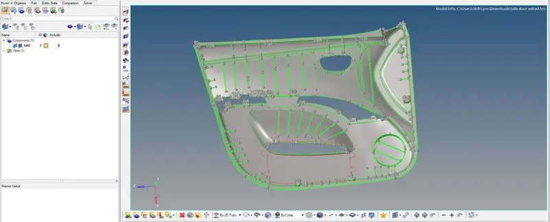
It will be tedious task if we continue to perform midsurface operation with the imported surface straight away, First we need to split the components into number of parts for our convenience.
2. To split the surface we need to use surface edit option available in geometry panel, we need to split the surface then save it into four separate collectors because the it will be convinent for us to generate the midsurface then

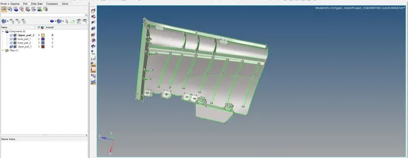
3. Once the surface are separated we can proceed for midsurface creation, here auto midsurface option cannot be used because by trail and error method we found out that auto mid did not capture the surfaces clearly so manual midsurface i.e., offset method is used here
- Under the surface edit option available in the geometry panel offset option is available, first we need to measure the thickness of the component using measure option ( Keyboard shortcut F4 )
- Then we need to select the surface to be offset after which the selected surface is duplicated and offset to the new collector created.
- It can be noted that all the four components have same thickness of 2.8 mm and the ribs present in the surface have varying thickness
- Also it should be made sure that the ribs present are extended into bottom surfaces.
Extracted midsurface:
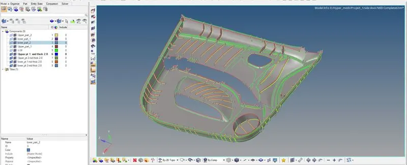
Midsurfaces after geometric cleanup:
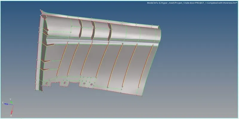
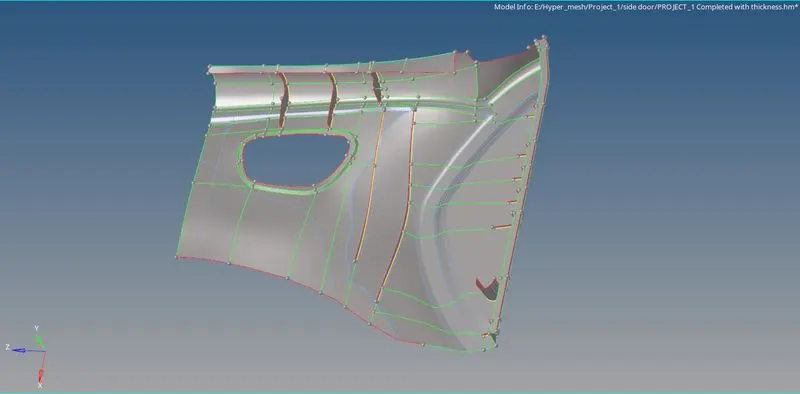
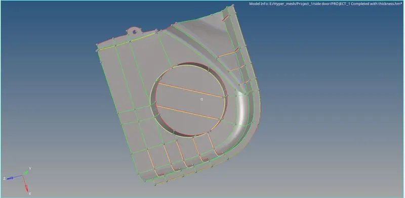
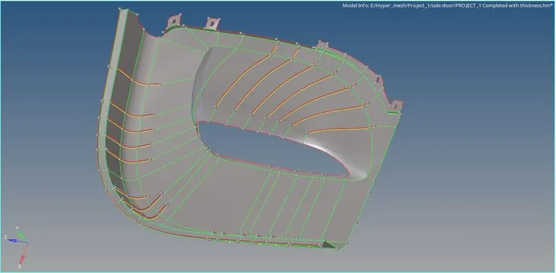
Here as we can see un necessary guide lines are toggeled and some cuts are made to the surface in order to attain a proper mesh flow
4. After the geometric cleanup is done we can proceed to meshing, which is available in the automesh option in 2D panel

Meshing is done in each component individually, to achieve proper mesh flow we need to mesh the component section by section which is created during geometric cleanup
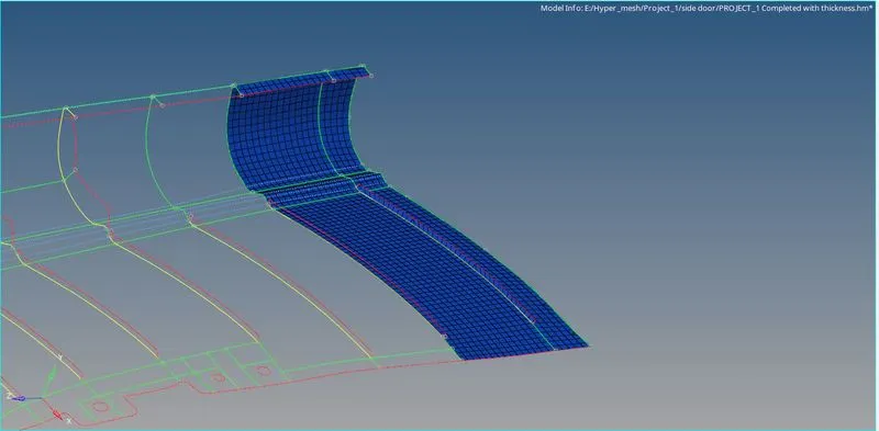
Initially the meshing should be started on either of the edges then it need to proceed inwards, Completed meshed surfaces as follows:
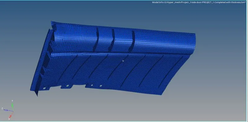
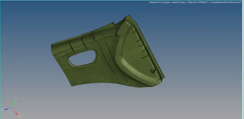
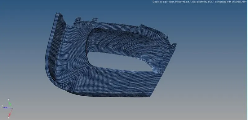
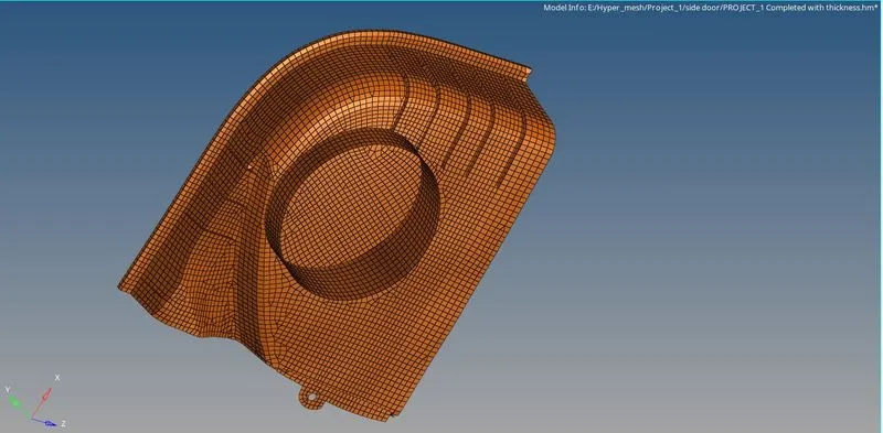
4. After creating the mesh we can notice that some elements are failing for quality especially in areas around the edges wrapage issues is found which can be cleared with the help of various tools available in the geometry panel and 2D panel.
The quality can be checked by using the check elements option ( Keyboard F10 ) available in tools panel or by using the quality index option available in the 2D panel
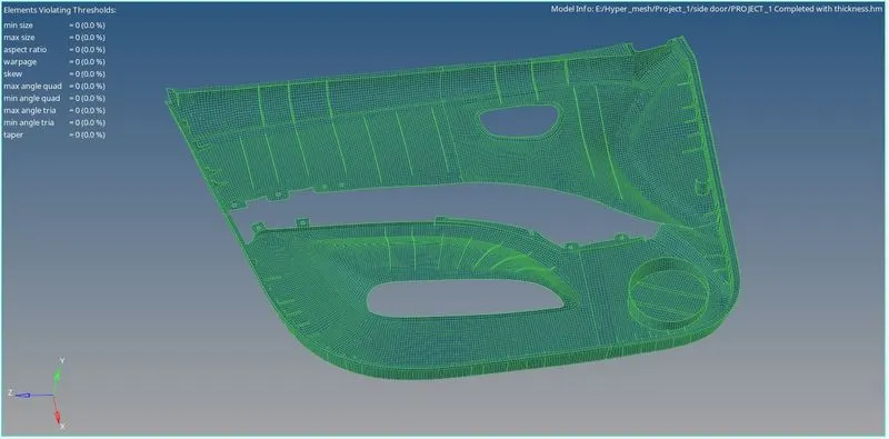
Here we can notice that all elements are clearing for quality and no element is failing in the entire component
5. To Assign thickness , to the components first we need to organize the ribs from the base according to the thickness
- To do so, the organize option available in tools panel is used, the rib's thickness is measured and a new collector is created according to the thickness of the ribs
- In such a way Ribs with thickness of 2, 3, 3.5, 4, 4.5, 5, 6.5 & 10 mm is created
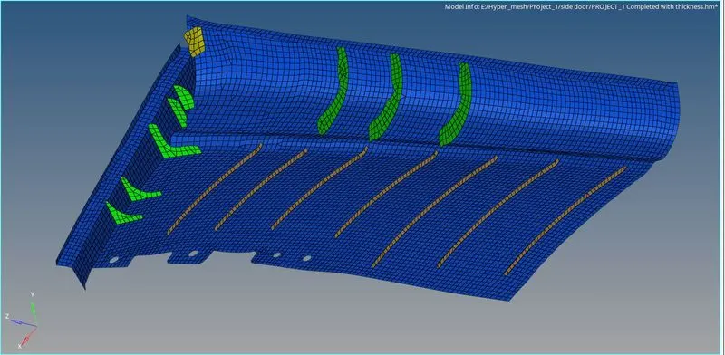
- So far we have only orgazied the ribs according to their thickness in order to assign thichness to it first we need to create a material card then a property card with the thickness of 2, 3, 3.5, 4, 4.5, 5, 6.5 & 10 mm for the ribs and 2.8 mm for the base surface
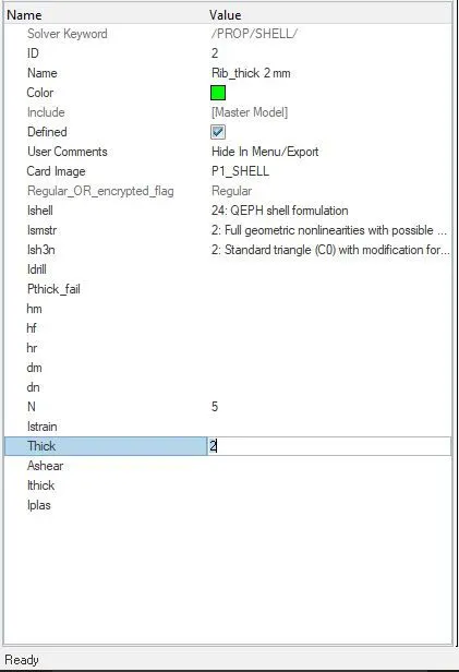
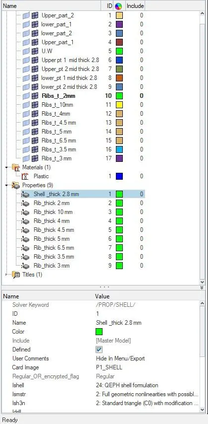
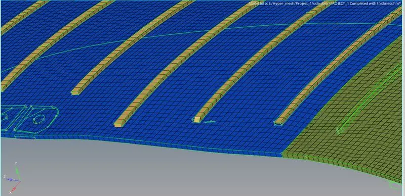
Detailed elemental representation after assiging thickness
Final Model Image:
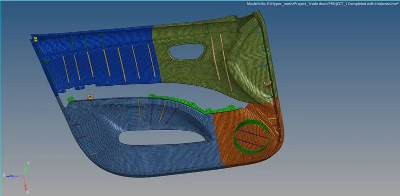
Detailed Representation
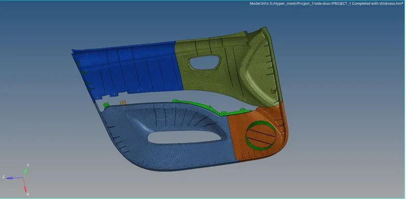
Traditional Representation
Conclusion:
Understood the different way of approaching the meshing of a plastic component by meshing the given side door panel with all elements clearing the quality and thickness is assigned with smooth mesh flow.