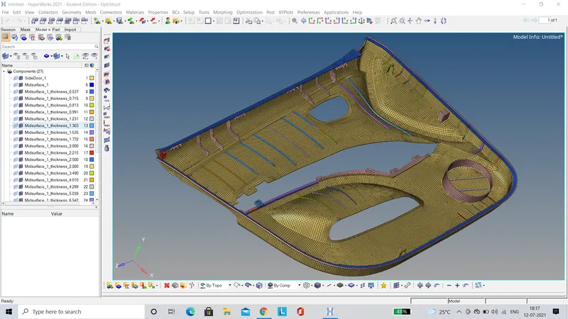
Week 12:Project-1-Meshing of Door Inner Panel Challenge
AIM
- To extract the midsurface of the given inner door panel manually.
- To mesh the component as per the given quality criteria.
- To assign thickness to the meshed components such that it aligns itself with the parent geometry.
PROCEDURE
Defeaturing
- The component that has been imported is defeatured to remove fillets and other contours which are less than the minimum element size provided in the quality criteria.
- This process is done to aid in the easy extraction of midsurface and also to avoid elements failing for minimum size during the meshing phase
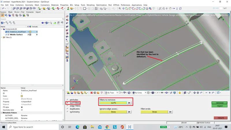
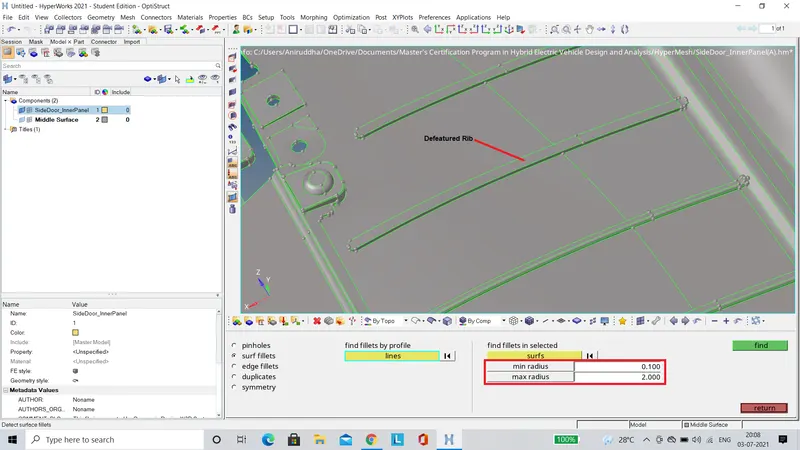
- In order to defeature the ribs present in the component, the 'Defeature' tool present in the 'Geometry' panel was used.Under the 'Defeature' window, the 'Surf fillets' option was selected.A group of surfaces are selected, and on selcting the 'find' icon, the tool automatically identifies fillets between 0.1 and 2 mm radius.The fillets to be defeatured can also be identified by selecting the lines defining the particular surface.
- The images below help in visualising the process.
Manual Midsurfacing
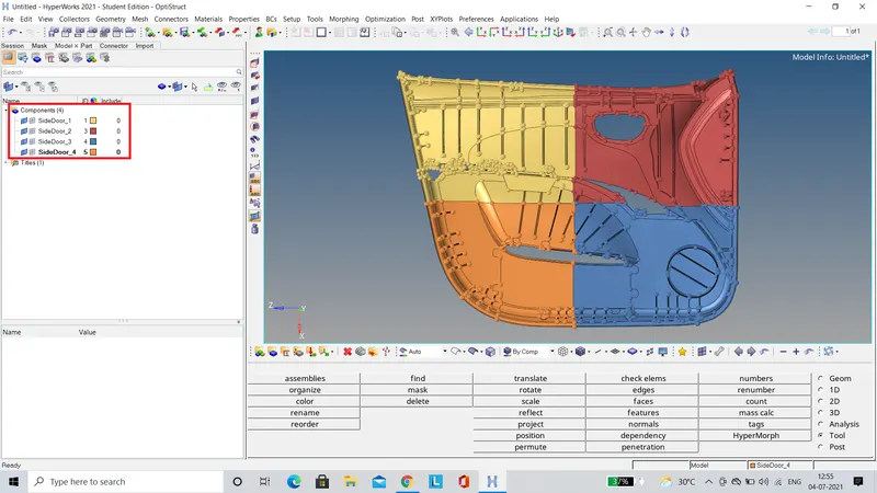
- Before, proceeding with the manual extraction of midsurfaces, the whole parent component was divided in to four components, to simplify the extraction process as shown in the image below.
- Now, the midsurface of each of the four divided components is extracted seperately.The average thickness of the components is measured, which was found to be 2.8 mm.
- Using the 'Offset' option under the 'Surface Edit' tool, the base surface of the particular component is offsetted to a distance of 1.4 mm towards the mid plane of the component as shown in the image below.
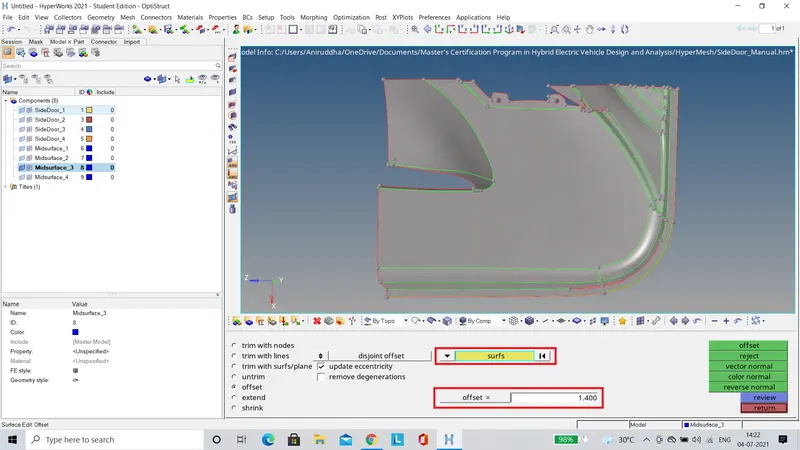
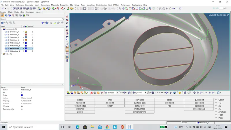
- The base surface was offsetted since it had no features to capture.After offsetting the base surface, the midsurfaces of the various features and ribs are extracted seperately based on their individual thicknesses as shown in the images below.
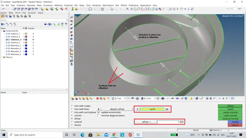
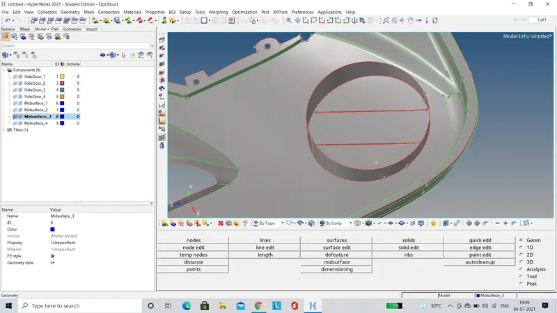
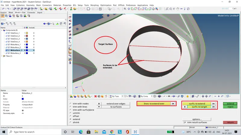
- From the above image, it is clear that the ribs are not connected with the base surface.Hence in order to establish a connection between the two, the 'Extend' option present under the 'Surface edit' tool is used.
- The process can be visualised using the images below.
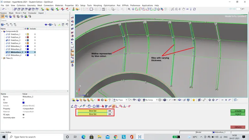
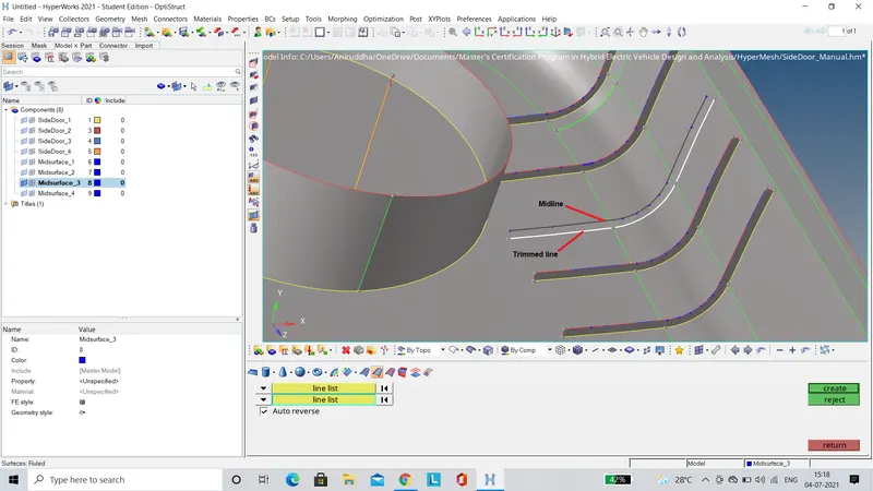
- There are certain cases where the ribs have varying thickness, hence offsetting the surfaces to the midplane is not feasible.For cases like these, a midline is created on the top face on the rib and then this midline is used to trim the base surface.Now using the 'Ruled' option present under the 'Surfaces' tool, a surface representing the rib is created between the two created lines.
- The above process can be visualised through the images below.
- Finally, after the midsurfaces of all four divisions have been extracted, they are organised into a single component collector.
Meshing
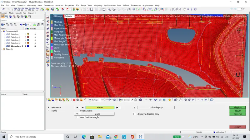
- Before proceeding with the meshing process, we have to define the quality criteria as shown in the image below.
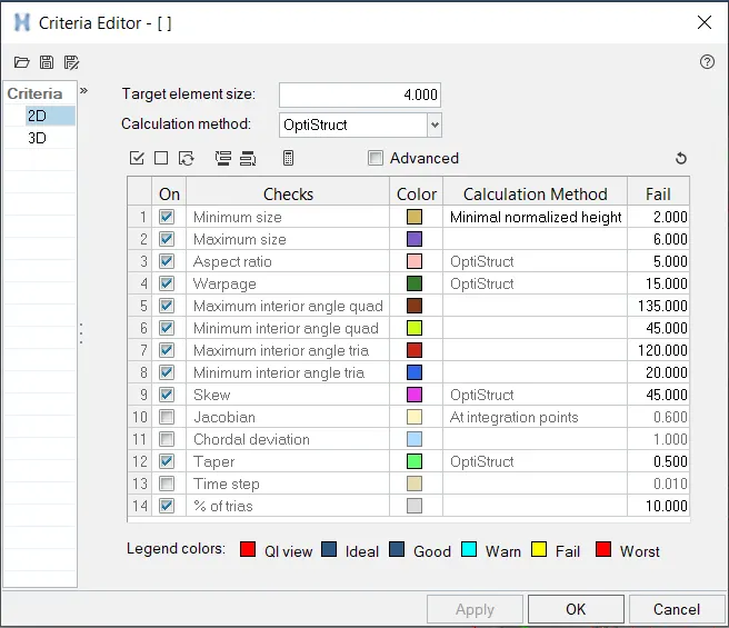
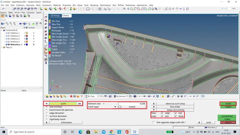
- Now, using the 'Automesh' tool under the '2D' panel, the various surfaces of the component are meshed one at a time.The element size is set to 4 units and the mesh type is set to 'mixed' as shown in the image below.
- In cases where the mesh obtained using the 'Automesh' tool is not satisfactory, the 'Rebuild Mesh' tool is used, which aids in providing a refined mesh most of the times.
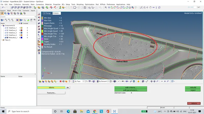
- Since we are preparing this model for crash and safety analysis, we have to avoid rotating quads at any cost.The tria elements are acceptable but should not conflict with each other ie. adjacent trias and trias facing opposite to each other should be avoided.Also it is not desirable to have trias in the fillet regions.
- The mesh should also be validated using the quality criteria defined previously, the elements which are failing should be rectified as far as possible.At certain intricate parts it is hard to avoid elements failing for minimum size.In our case there are 41 failed elements, all of which are failing due to minimum size.Most of the quality issues can be rectified using the 'Quality Index' tool present in the '2D' panel.
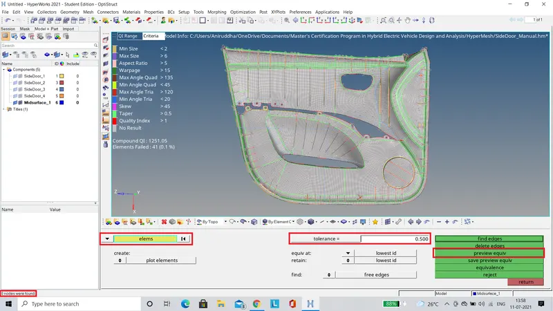
- After meshing the whole component, it is necessary to check the mesh created for free edges and equivalence, which if present have to be rectified accordingly.
- We also have to do the normal and dependency check.While doing the normal check we have to make sure that the normals of all the elements are facing in the same direction.In the image below it can be seen that a few elements have normals in the opposite direction.
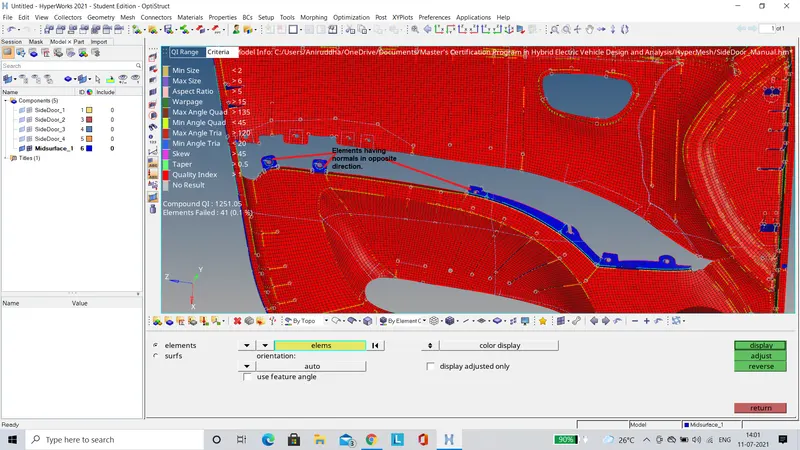
- The elements having normals in the opposite direction are selected and then the direction is reversed, hence obtaining the desired orientation as shown below.
Assigning thickness to the mesh
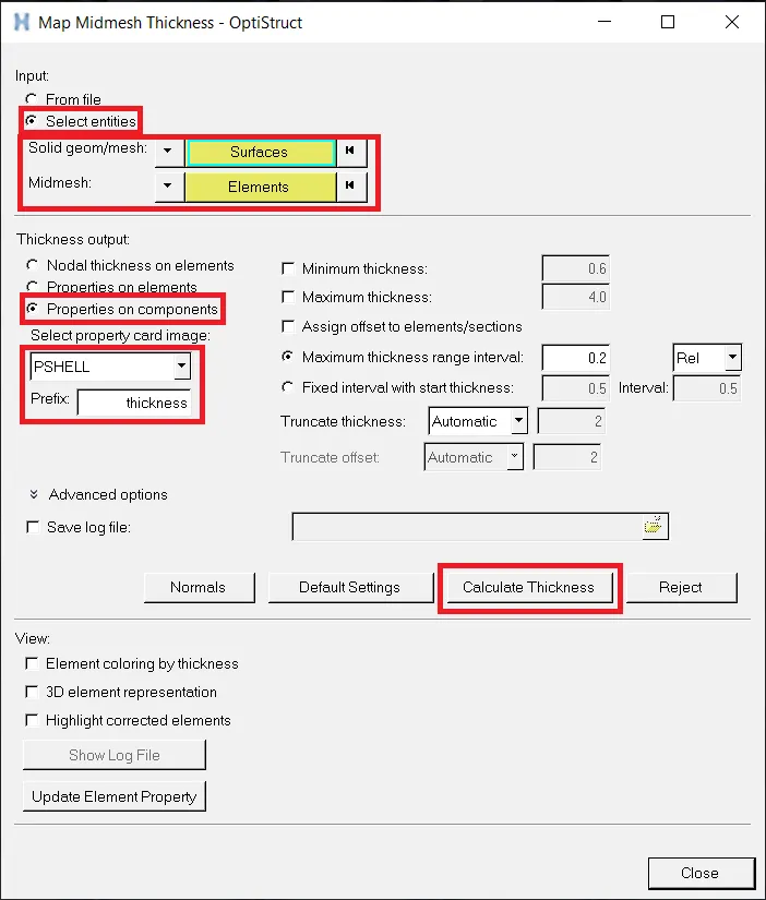
- Using the 'Midmesh Thickness' tool, we can assign the thickness to the mesh automatically.The tool by itself measures the thickness of the various features of the component and then assigns the thickness to the mesh accordingly.
- The input is set to 'Select entities', where we have to select the parent surface as well as the mesh we have created.Based on the thickness of the parent surface, the tool assigns the appropriate thickness to the mesh.
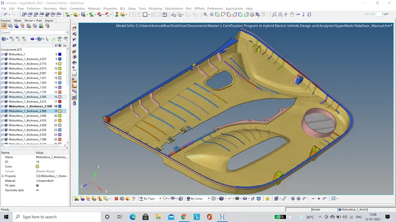
- After the thickness has been assigned, we have to switch to '2D Detailed Element Representation' to visualize the thickness assigned.
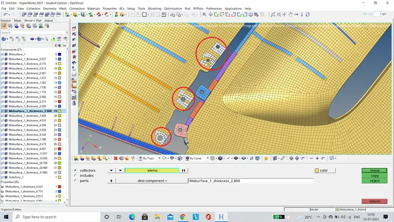
- The 'Midmesh Thickness' tool generally assigns the thickness perfectly, but there may be few regions in the mesh where the right value of thickness is not assigned as shown in the image below.
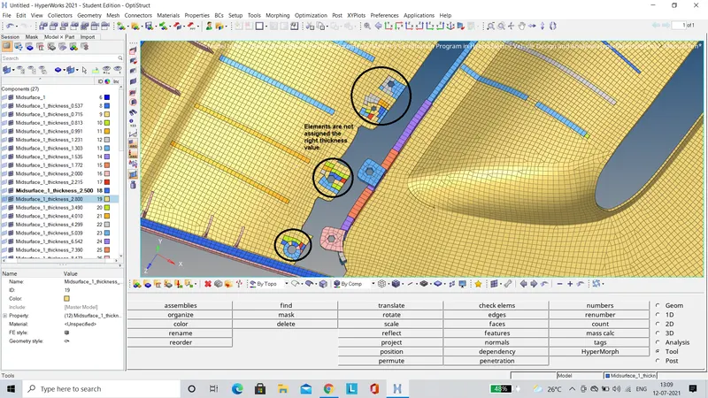
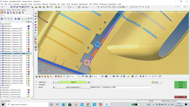
- To rectify this problem, we have to organise the elements in the appropriate component collector as shown in the images below.
FINAL MODEL IMAGE