Meshing the Side Door Trim in Hypermesh
Meshing of the Side Door Plastic Component.
Aim: To create the Midsurface and Mesh the given Side Door Plastic Component according to the Quality Criteriia given below. Also Thickness is to be assigned to the mesh.
Target Element Length = 4mm
| S.N | Quality Criteria | Value |
| 1 | Aspect Ratio | 5 |
| 2 | Skewness | 45 |
| 3 | Warping | 15 |
| 4 | Taper | 0.5 |
| 5 | Min. Length | 2mm |
| 6 | Max. Length | 6mm |
| 7 | Min angle Quad | 45 |
| 8 | Max angle Quad | 135 |
| 9 | Min angle Tria | 20 |
| 10 | Max angle Tria | 120 |
| 10 | Tria % | 10 |
1. INTRODUCTION: About the Side door Plastic component.
- The given component is the inerior part of the Side door of a car which is called as Side Door Plastic component.(refer fig 1.1)
- It is made of plastic since the thickness of the component is non-uniform over the entire component.
- There are three types of plastic used in the Automobile industry. They are
- Polyurathene plastic
- Polypropylene plastic
- Poly vinyl chloride(PVC)
- There are other types of plastic used in the automobile industry other than above three types of plastic.
- They are ABS plastic, polystyrene, polycarbonate, PMMA, etc.
- Figure 1.1 shows the image of the Side Door Component.
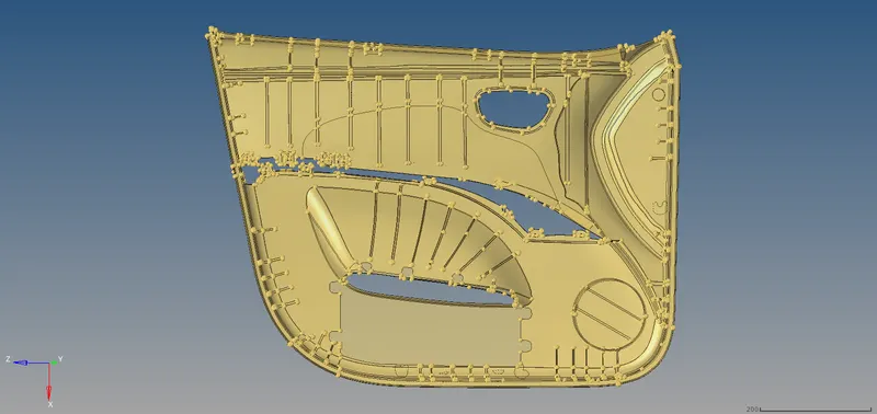
Figure 1.1
2. FEATURES: Side Door Component.
- This Side Door Interior component consists of a slot for attachment of door lock mechanism, cylindrical component for attachment of speaker, slot for attaching the storage compartment.(refer fig 2.1)
- Also it has number of ribs to increase the strength of the component.(refer fig 2.2)
- These ribs have various thickness in different locations.(refer fig 2.3)
- There are many holes for attaching the other components to the Side Door Component using the plastic studs.(refer fig 2.4)
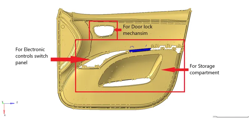
Figure 2.1
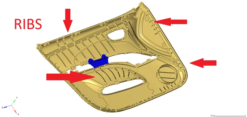
Figure 2.2
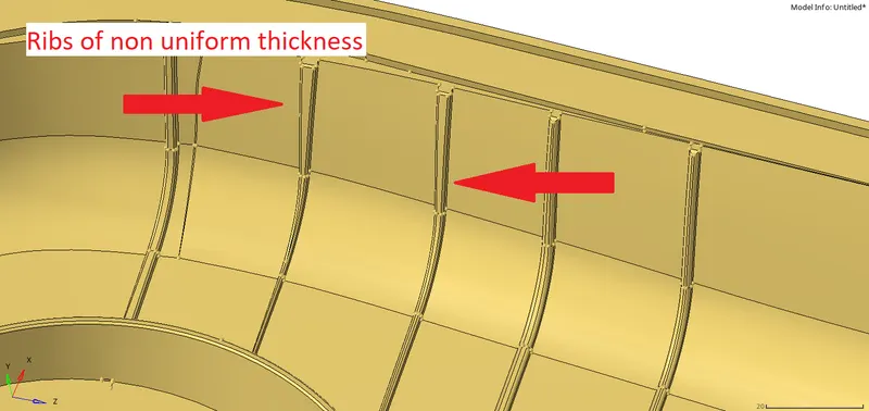
Figure 2.3
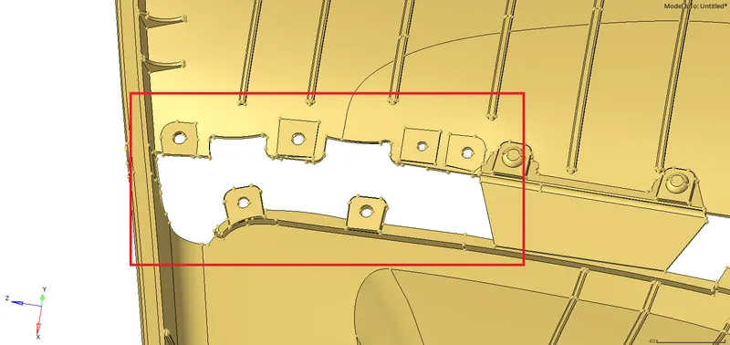
Figure 2.4
3. PROCEDURE: To create midsurface, mesh and assigning thickness.
- The stages in meshing the component
- Import the model.
- Create the Midsurface.
- Mesh as per the given Quality criteria.
- Assigning the Thickness to the mesh.
- 2D meshing is made on the surface since the thickness of the component is very less(less than 5mm), also creating 3D meshing involves many nodes and elements which consumes more space and requires more time for further analysis.
- Therefore a surface is genrated such that on assigning thickness it ressembles the actual component, this surface is called as Midsurface.
3.1 IMPORTING THE MODEL.
- To import the model first file format of the given component is to be known.
- The given component is in the hypermesh format i.e Side_Door_mesh.hm.
- To import the .hm file File>Import>Select the type of format>Browse file by clicking the folder icon>Select the file>Import.(refer fig 3.1.1)
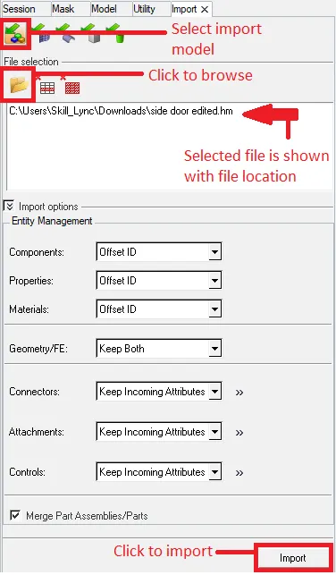
Figure 3.1.1
3.2 CREATING THE MIDSURFACE
- Midsurface can be generated by two ways; Auto midsurface and Manual midsurface.
- For this component midsurface is generated using Manual midsurface procedure.
- To create manual midsurface the thickness of the model is to be known.
- To find the thickness find the distance between the two points between the top and bottom surface Geom>distance> select the points between top and bottom surface.(refer fig 3.2.1)
- The average Thickness of the component, excluding the ribs, was found to be 2.8mm.
- To create midsurface first create a new component where the midsurface is to be created.
- Then the outer surface is offset half of the thickness of the component
- Geom> surface edit> offset> select the inner surface by face> dupicate> current component> set the distance to half of the thickness i.e1.4mm > offset.(refer fig 3.2.2)
- Now to create the midsurface of the ribs there are three ways to generate midsurface
- Offsetting the side surface of the rib
- Using Auto-midsurface
- Creating midline and extending the line to the surface
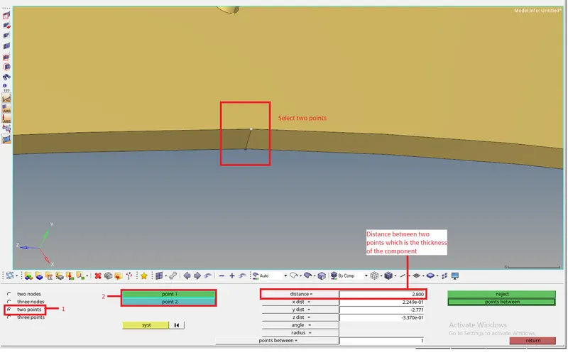
Figure 3.2.1
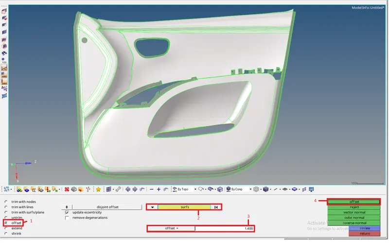
Figure 3.2.2
1. Offsetting the side surface of the rib.
- These ribs have fillet at the all the ends, hence defeature all the fillets.
- To defeature the ribs Geom>defeature>surface fillet>set the min and max radius of the fillet>select the rib surface>Find>now the fillet will be highlighted>Remove.(refer fig 3.2.3 and fig 3.2.4)
- After removing the fillets the side surface of rib is offset half of the thickness.
- Offsetting is done by following the above procedure of offsetting.(refer fig 3.2.5)

Figure 3.2.3
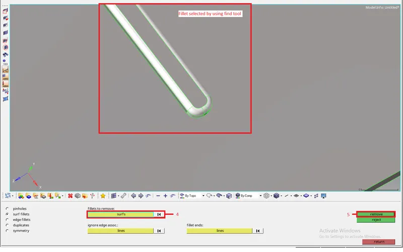
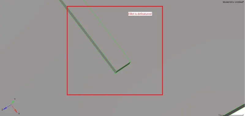
Figure 3.2.4
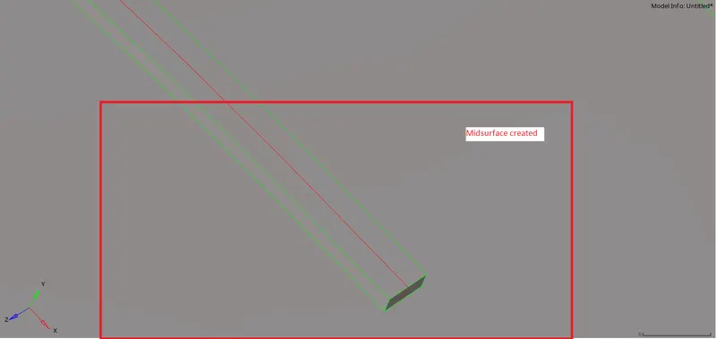
Figure 3.2.5
2.Using the Auto-midsurface
- To create misdurface the surface using auto midsurface the ribs should not have fillets hence fillet is to be defeatured.
- To create the midsurface using the Auto-midsurface, Geom>midsurface>Change the extracting option to offset>change the closed solid to incomplete solid in the auto midsurface option> untick the select outbound surface>select the surface of the rib on either side.>extract.(refer fig 3.2.6)
- This will create a new component named Midsurface and the midsurface of the rib will be there in that component.
- This procedure will work better on the ribs without fillets.
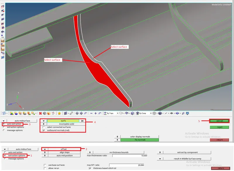
Figure 3.2.6
3. Creating the midline and extending the line to the surface.
- In this procedure a line is created in the middle of the top surface of the ribs.
- To create a line in the middle of the surface Geom>lines>Lines between>select the edges of the ribs>create.(refer fig 3.2.7)
- A line will be created in the middle of the surface now trim the midsurface of the outer offset surface using the trim with lines.
- To trim the surface geom>surface edit>tim with lines>Select the surface> change the vector to normal to surface>select the free lines>Trim.(refer fig 3.2.8)
- The midurface of side door will be trimmed. Now create surface using these lines.
- To create surface using the lines Geom>Surface>Ruled>select the lines>create.(refer fig 3.2.9)
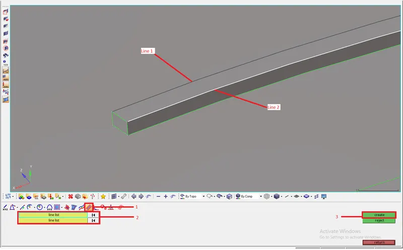
Figure 3.2.7
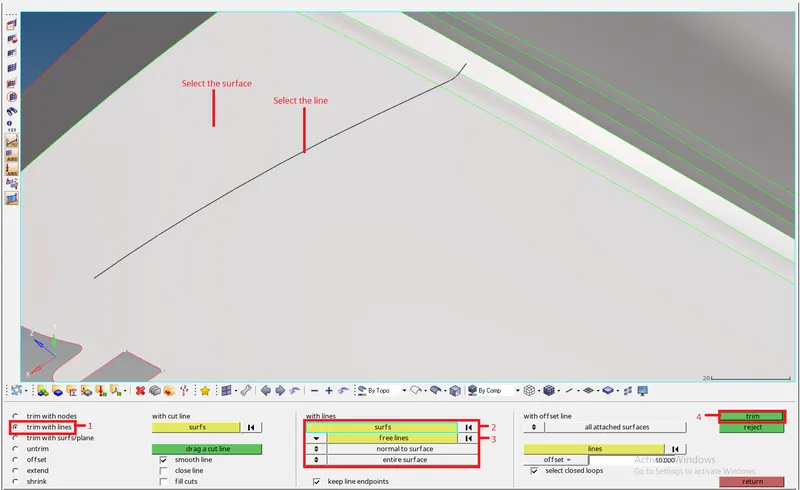
Figure 3.2.8
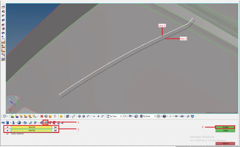
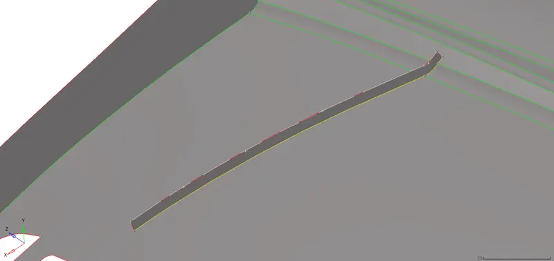
Figure 3.2.9
- To creating the midsurface of the cylinder in the component follow any of the three procedure described above.
- Here Offset procedure is followed ot create the midsurface of the cylinder.
- Even after creating the midsurface of the ribs and cylinder, these surfaces are not attached to the main midsurface.(refer fig 3.2.10)
- To connect these surfaces onto the midsurface extend the rib and cylinder midsurface onto the main midsurface.
- To extend these surface Surface edit>extend>change max extension to surface over edges>change cross extension to surface to target> select the edge of the ribs> select the outer midsurface as surface to target>Extend.(refer fig 3.2.11)
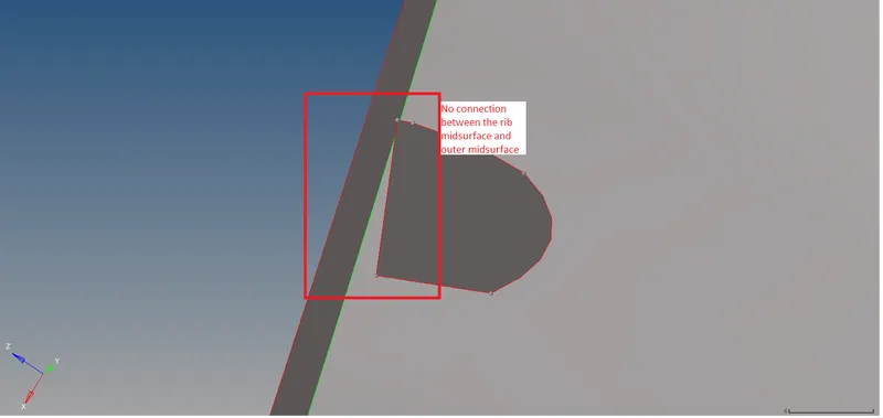
Figure 3.2.10

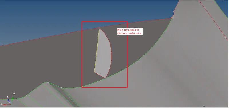
Figure 3.2.11
3.3 GEOMETRY CLEAN-UP OF THE MIDSURFACE
- After attaching the rib surface onto the outer midsurface, it is to be cleaned i.e to remove uneccessary trim lines which will make elements to fail.
- In this midsurface there are many trim lines which are uneccessary and is toggled using toggle edge tool.
- Some of the lines toggled are shown below.
- After toggling surface are trimmed using surf-node trim and surf-line trim tool in the quick edit pane to create segments of surface for better mesh flow and quality.
- Some of the trim lines on the midsurface are shown below.(refer fig 3.3.1)
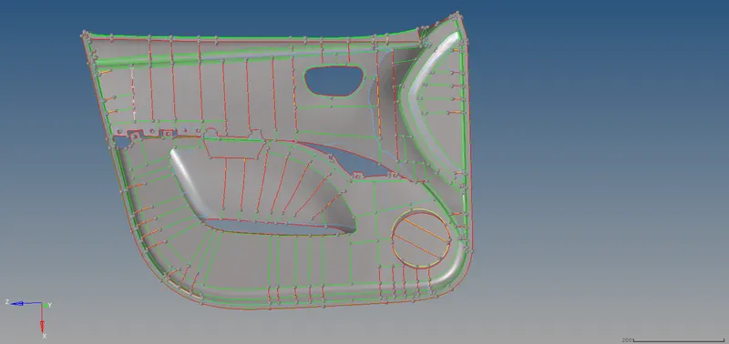
Figure 3.3.1
3.4 MESHING THE MIDSURFACE
- To mesh the generated midsurface as per the given quality criteria, first quality criteria is to be set.
- To set the Quality Criteria Values Preferences>Criteria File Settings.(refer fig 3.4.1)
- Enter the values of the Quality criteria given and save the criteria file for further use.
- Saving the criteria file helps in saving time as it changes to default values on closing the Hypermesh.
- To mesh the surface 2D>automesh>select the segments of the midsurface and clear the failed elements side-by-side inorder to get good mesh quality and mesh flow.(refer fig 3.4.2)
- To clear/repair the failed 2D>Quality Index>Use cleanup tools such as Element optimize, Smooth, Swap edge, drag tria, etc. to clean up the mesh.
- The following rules is to followed while meshing
- Feature Capturing
- Mesh flow
- Quality Criteria
- Tria Management
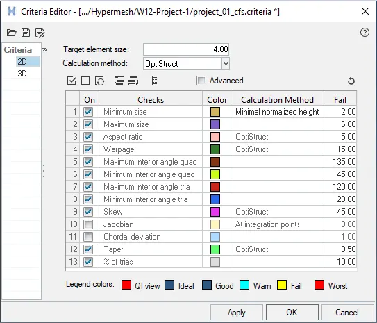
Figure 3.4.1

Figure 3.4.2

Figure 3.4.3
- Also there are some importent parameters in tria management.(refer fig 3.4.4 and 3.4.5)
- No trias in corners/free edge
- No opposite trias
- No back to back trias
- No trias in fillets or hemings
- No rotational quads
- No trias should share boundry with feature line
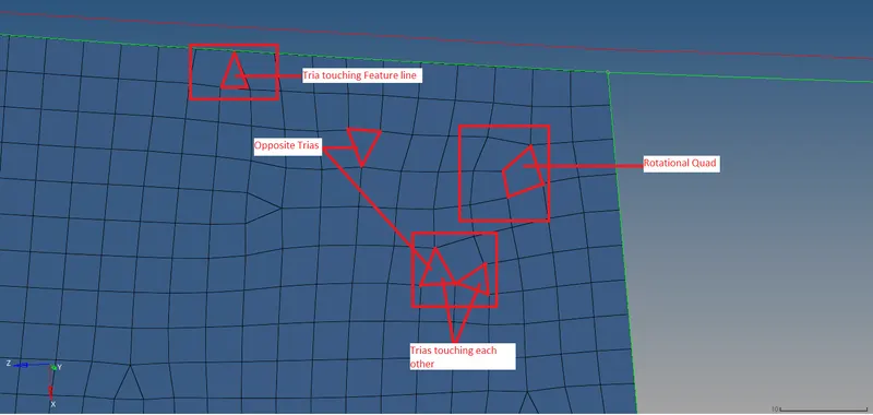
Figure 3.4.4
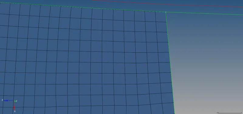
Figure 3.4.5
3.4.1 ELEMENT CLEANUP
- Using the cleanup tools in the Quality index tool elements are repaired as per the above parameters.
- Drag Tria is used to drag the tria elements and can join opposite trias in the mesh.
- Element optimize is the tool used to clear the element failure according to the Criteria file.
- Split quad is used to split the quad element into two trias.
- Combine trias is used to combine two opposing trias touching side by side.
- Smooth is the tool used to smooth the flow of the mesh thereby removing some failing elements.
- If these cleanup tools unable to repair the element failing those elements is remshed.
- Remeshing is meshing the elements again which are failing for quality criteria.
- Also Rebuild mesh is used to remove the failing elements.
- To rebuild mesh 2D>rebuild mesh>Select the elements which are failing and also select the elements around the failed elements.(refer fig 3.4.5)

Figure 3.4.6
3.5 ASSIGNING THICKNESS TO THE MIDSURFACE
- After meshing the component next step is to assign the thickness to the component.
- Since this component has different thickness at different places respective thickness is to assigned to that elements.
- To assign thickness properties is to be defined.
- To define a property right click on the model panel>create>property.(refer fig 3.5.1)
- Now select the property Another panel is opened below the model view.
- In that panel set the thickness to a certain value according to the model.(refer fig 3.5.2)
- In this model 15 property is created inorder to assign the thickness to the component.
- To assign the thickness, elements of same thickness is to be in single component.(refer fig 3.5.3)
- After segrigating the elements of different thicknesses into different component right click on the component and select assign.
- Now new tab will open in that tab select the thickness to be assigned to a particular component.(refer fig 3.5.4)
- After assigning the thicknesses to check whether thickness is assigned or not select the 2D traditional representation to 2D Detailed representation.(refer fig 3.5.5)
- All the elements will become thick and those elements which are not assigned the thickness will look as surface.(refer fig 3.5.6)
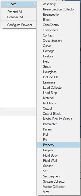
Figure 3.5.1
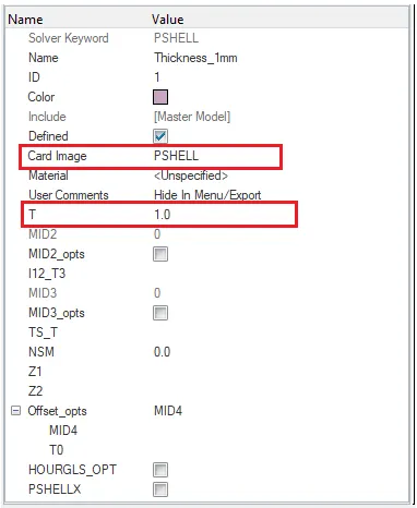
Figure 3.5.2
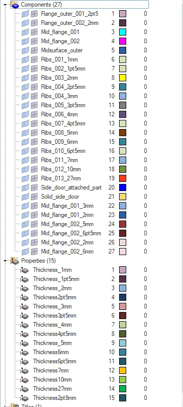
Figure 3.5.3
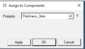
Figure 3.5.4
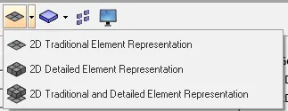
Figure 3.5.5
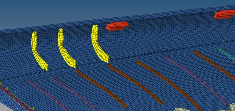
Figure 3.5.6
3.6 IMAGES OF THE SIDE DOOR COMPONENT AFTER COMPLETE MESHING
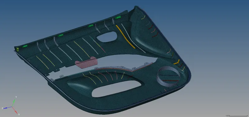
Figure 3.6.1 Component displayed By Property.
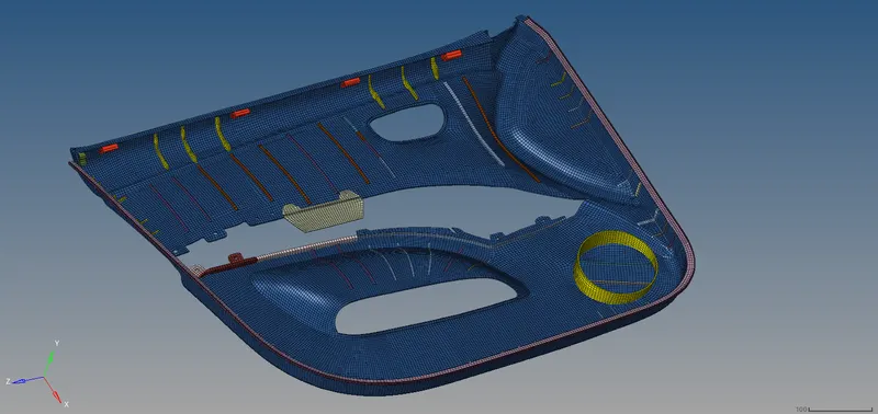
Figure 3.6.1 Component displayed By Component.
CONCLUSION: The given component had a average thickness of 2.8 mm hence 2D meshing is done, according to the given Quality Criteria, on the midsurface created from the component and assigned the thickness.