Shell Meshing on a Side Door Trim using Hypermesh
Project 1 Report.
- Aim: To successfully extract a mid-surface and mesh the given model of a Side door.
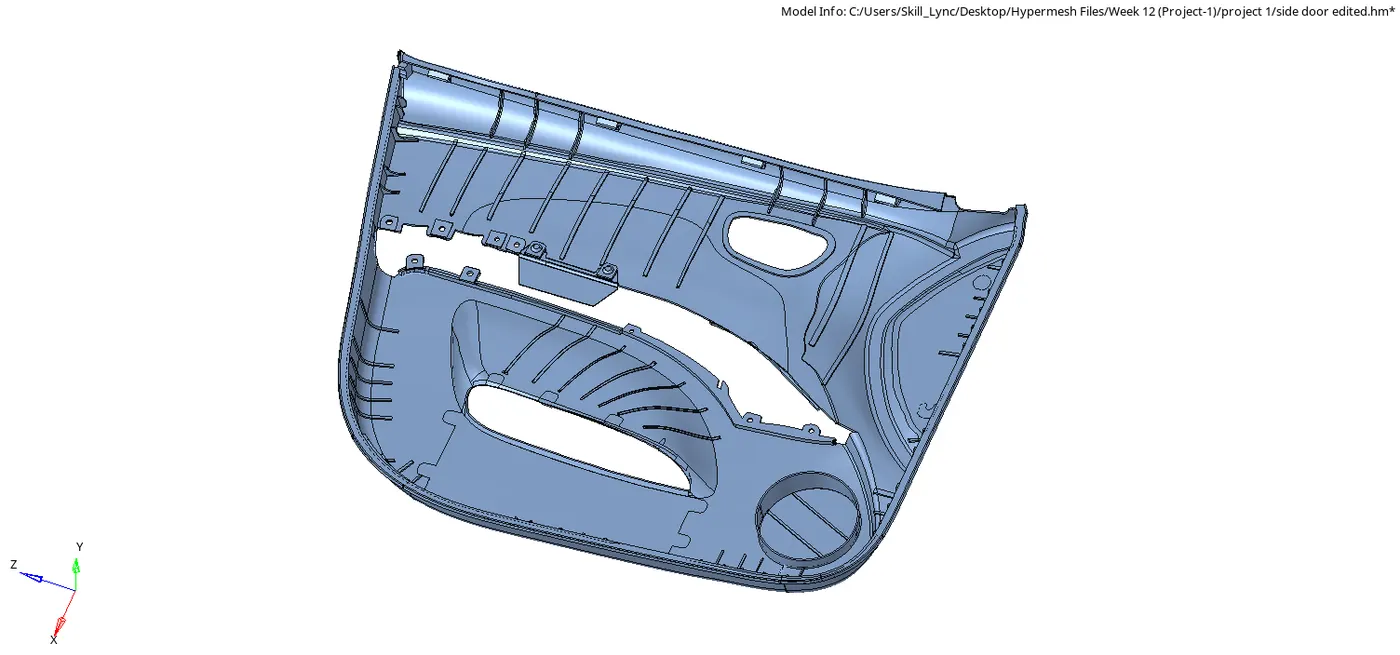
Initial Given model - Objectives: 1. To geometrically clean the given surface for any errors in it.
2. To extract a proper mid surface for the component.
3. To clean the midsurface so as to avoid any minimum length errors in it.
4. To mesh the component with minimum number of tria elements and clearing all the Quality criteria set for the model.
5. To assign thickness to the various parts in the model. - Procedure:
1. To begin with the meshing procedure on the model, the very first step is to Geometrically Clean the model right after we import it. There might be the presence of some errors during the importing process. Another important step during the geometric clean up is the process of defeaturing the all the fillets in the model as the middle surface of them will give tria elements at the edge. So we can either remove them on the parent surface or we can remove them on the mid-surface.
Geometry -> Defeature
Defeature Command.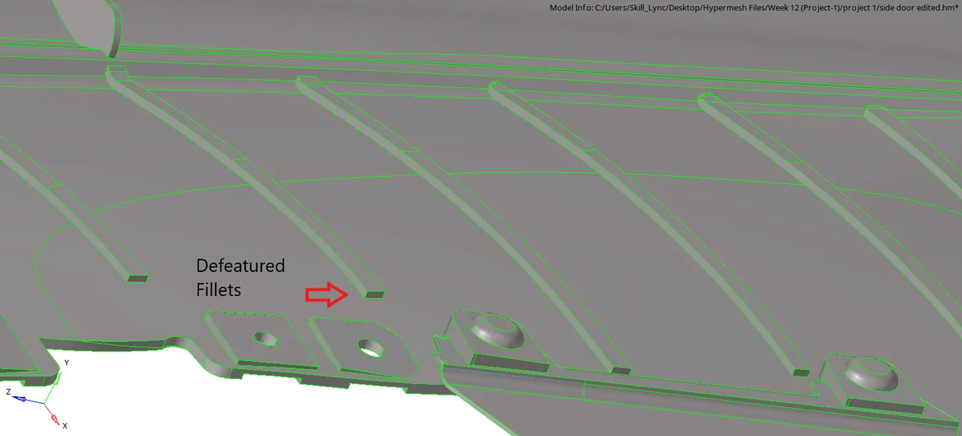
Example for Defeatured Fillets
This is how we can defeature a fillet and thus make the mid surface extraction much more easier and smoother. When we defeature the fillets, we need to check for the presence of any free edges where they should not be there. For this, we can change the surface view to "By topo" and see all the Free edges on the surface.
2. After the defeaturing is done, we then go on to extract the mid surface of all the various parts in the geometry. There are various methods by which we can extract the mid surface of the component. One method is to measure the thickness of the component, and then offset one face of the part to the middle of it. To do this, we can use the surface edit option (Shortcut- Shift+F9) and use the offset command under it.
So, For example, If the thickness of a component is 2.8mm, we need offset one of the faces by 1.4mm. To measure the Distance between two points, we need to use the distance command (shortcut- F4)
Distance command.
We can alter between the available options and measure the distance between two and three points or nodes. The Distance option in it will give out the distance between the two points.
After we get the thickness of the component, we then offset one of the faces by first duplicating it into a particular component. Because of the duplication process was done, we will have the surfaces in both the parent and the midsurface of the component.
Offset command.
Another method is to simply extract a surface right in the middle of the part. To do this, we can use the Midsurface command in the Geometry tab. And in this option, we can use the Final Edit tool. We need to use the Surface pair option in it.
Geometry -> Midsurface
Final Edit Tool command.
In this command, we simply need to select both the surfaces at the ends of the part. Like this, we get a surface in the exact middle of the component. The middle surface will be saved in a different collector called "Middle Surface". We then have to move these newly created surfaces to the middle surface that we have created.
To do this, we need to use the Organize tool in the Tools Tab.
Tool -> Organize
Organize Command.
We then move the surfaces to a Destination component accordingly.
Using all these various tools, we then go ahead and extract the mid surface of all the geometrires in the entire component.
3. The next step would be to extend the ribs onto the base of the mid surface. To extend the ribs, we can use the extend option in the Surface Edit command (shortcut - Shift+F9). The Tool path is Geometry -> Surface Edit.
Geometry -> Surface Edit

Surface Edit Command.
We then select the lines on the surface to extend under the "Lines :to extend over" and then the Surface on which it is to be extended are to be selected under the "Surfs: to target" option. We then get an extended face onto the taget surface.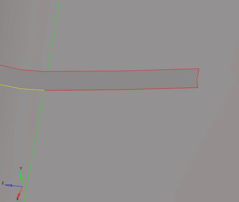 Before Extension.
 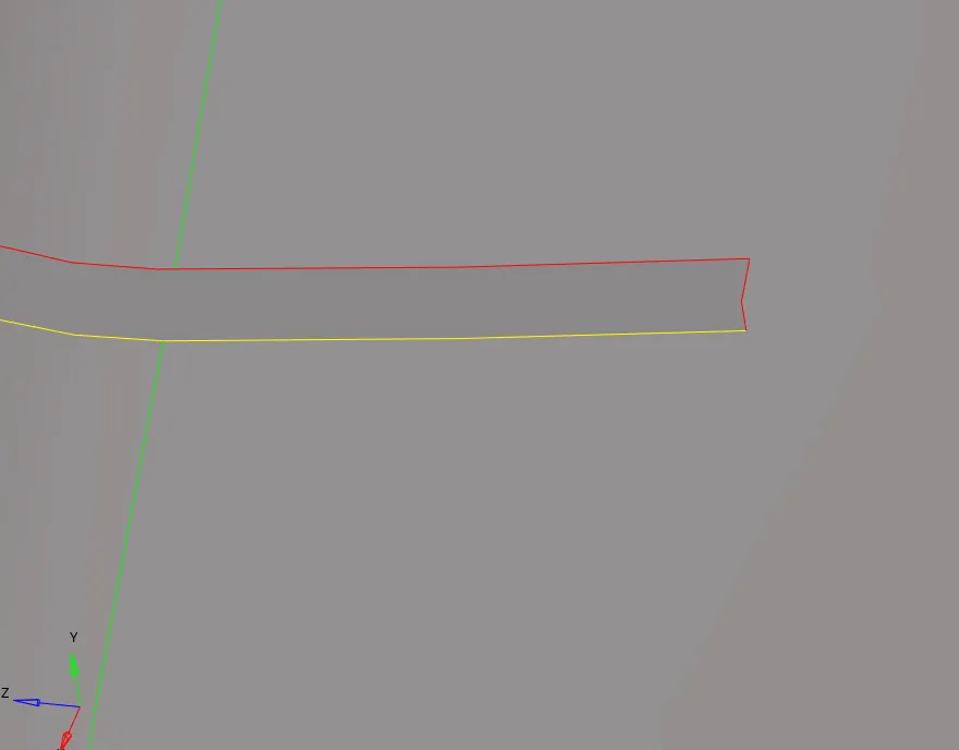 After Extension.
Using this method, we then extend all the ribs onto the base of the mid-surface and complete the mid surface with all the features and ribs. The mid-surface of the entire Side-Door trim should look like the following: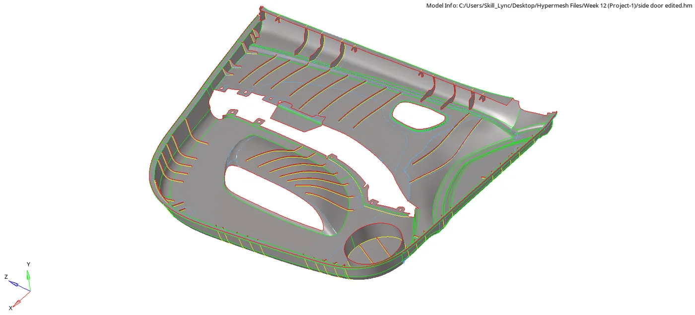
Final Mid-surface of the component.
4. After the Mid-surface was extracted, we then proceed to mesh the surface. Before meshing the component, we first set the Quality Criteria given for the component. To set the Quality Criteria, we go to Prefences and select the Quality Criteria option in it.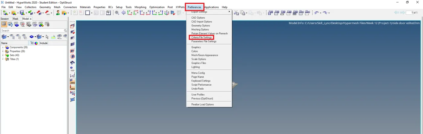
Preferences -> Criteria File Setting.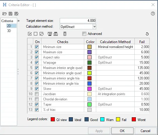
Quality Criteria for the component.
5. After the quality Criteria was set, we then proceed to mesh the mid-surface. To mesh the surface, we firstly need to clean the mid-surface to avoid any minimum length errors in the mesh. We basically trim off the lines and points where the mesh will form any elements with minimum length errors. We simply Toggle these lines using the Quick Edit panel (shortcut-F11) making sure that the Feature is captured properly.
To Mesh the component we use the Automesh command (shortcut - F12) in the 2D Tab. We then set the average element length and select the type of elements as "Mixed". We also select both the Align and Size options to get a much better Mesh flow.
2D -> Automesh.
Automesh Command.
We then Mesh the entire component part by part so as to get a much better control on the flow of the mesh and tria percent as well. In this method, we will divide the entire component into a certain number of surfaces and then mesh them surface by surface.
We need to make sure that no tria element is touching each other and also not present on the Shared Edge of any feature. We also need to avoid any Rotational Quads or Fixed/Pattern Tria Elements. To fix these issues, we need to simply remesh these regions and resolve the rotational Quads into Two seperate tria elements in two different Directions and the fixed tria into three different tria elements. These Tria elements are needed to managed and are to be prefered over the Rotational Quads and Fixed Trias.
After Meshing these surfaces, the component will look something like the following: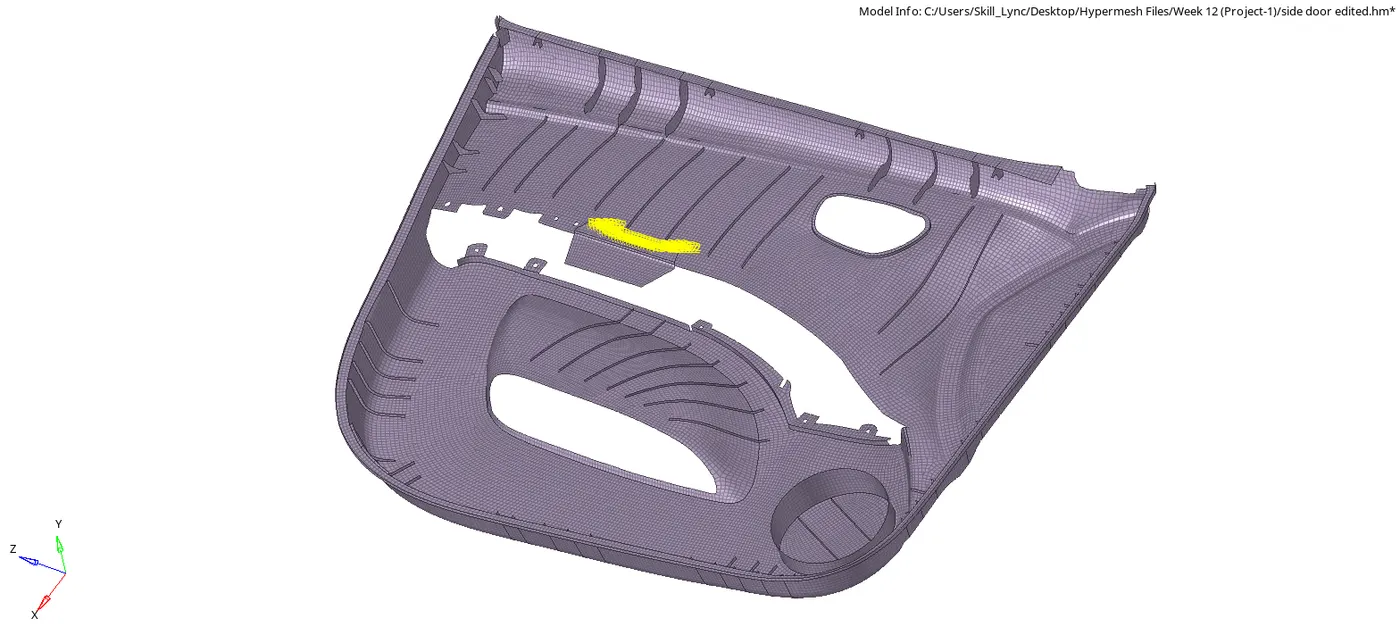
Final Meshed Component.
6. The next step in the meshing process is to check for the elements that have failed the Quality criteria that was set earlier. To do this, we need to check at two places. Firstly go to the 2D Tab and select the option of Quality Check and view all the elements that have failed for all the Quality, like for example we can view all the elements that have failed for Minimum length or even aspect ratio or warpage etc.
2D -> Quality Index
After we identify such elements, we then go on to rectifying them. If the elements are failing for minimum length, then we can increase the length for the edge that is failing for minimum length. Or if the element is failing for maximum length then we can simply reduce the length that is failing for maximum length.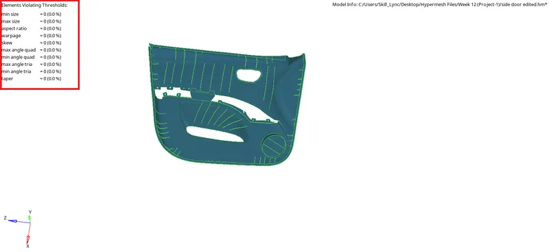
No Elements are failing for the set Quality criteria.
The other place is to check for Quality check (shortcut-F10). We then need to input all the values according to the Quality criteria given. We then click on all the Quality Criteria set and view all the elements that have failed for a particular Quality criteria. The Quality criteria need to be cleared before submitting the model.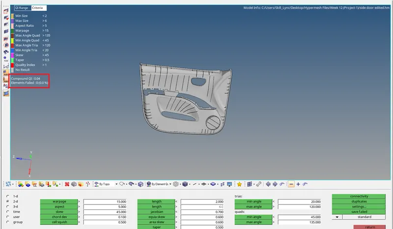
We can see that the total number of elements that are failing for that particular Quality criteria is zero.
7. Now that the model has cleared all the required Quality criteria, the next step is to assign thickness to the various components in the model. Certain components may have uniformly varying thickness or some components may have uniform thickness all over. To assign thickness, we need to firstly need to seperate all the component with similar thickness into a particular component. Like for example, If two ribs have similar thickness then we need to put them into one component. To create a new component, we need to right click on the tree and select the option of create.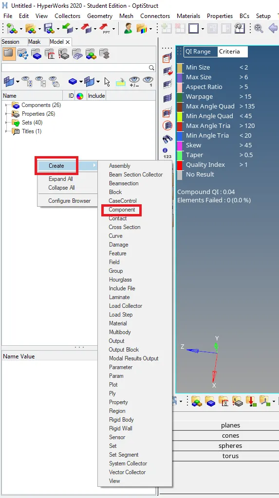
Creating Component.
If for example, the component has a thickness of 2mm, then we can name the component as "comp_2mm".
So, like this we can create seperate components for seperate set of thickness in the component.
To assign proper thickness to the component, we need to assign a property to it. In this property, we need to assign the thickness that we are needed to assign to that particular component. To create a property, we again need to right click in the tree and select the property option in it.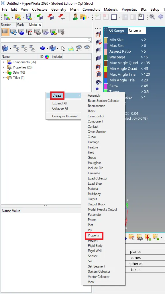
Creating Property
This is how we can create a property. Now, to assign thickness, we simply need to open the property tab and assign the value under the option of "T" as it represents thickness.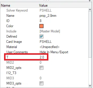
Thickness assigned as 2mm.
As shown, the property is created for all the components with thickness as 2mm, so the value for "T" in this case will be 2mm. Just like this we need to create different properties for different thickneess in the model.
Now for the thickness to refelct in the component, we need to assign this property to the component that was created for 2mm thickness. To assign the property to the component, we need to right click on the component and select the assign option. Under this we need to select the property option and select the property that was created for that particular thickness.
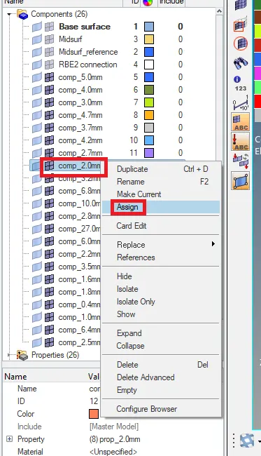
To assign a property to a component.
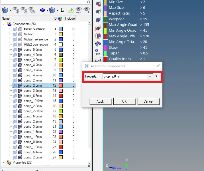
Property for 2mm component.
8. Like this, we need to assign all the different properties to their respective components. And to finally view the thickened mesh, we simply need to change the view from "2D Traditional Element Representation" to "2D traditional and Detailed Element Representation." This can be done by changing the view from the below given way.
Element viewing tab.
The final model with all the thickness assigned to it, will look like the following: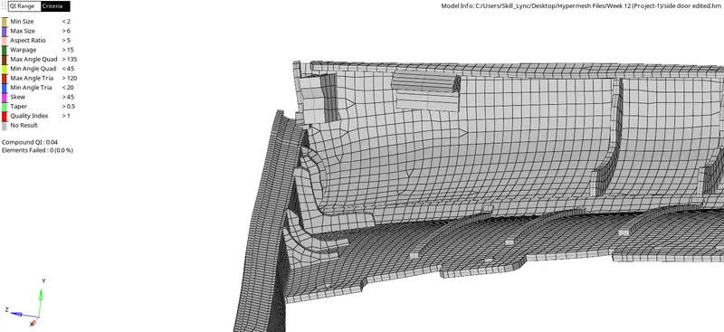
Elements with Thickness assigned.
9. The next step in this of model is to create an RBE2 Connection between the plate and the main body of the Side Door trim. To create such 1D Connections, we need to use the option of Rigid under the 1D tab.
1D -> Rigid.
After selecting this option, we then need to simply select a pair of nodes, one on each surface, i.e. the plate and the main body of the side door trim and connect them with an RBE2 (Rigid Body Element) connection. This will simply connect both the plate and the main body and constraint the plate according to the given Degree of Freedom.
10. After the Rigid connections were made on the model, the final step would be to check for Free edges and Element Normals on the component. To check for the Free edges on the component, we need to use the shortcut of Shift+F3 and select the option of free edges. We then need to select all the elements and view for any errors in the Free edge of the component. If there are free edges somewhere in the middle of the component (except in the case of a hole) then we need to fix it by checking for the connectivity between the nodes. If the connectivity is missing then we need to connect them using the node connectivity (Shortcut- F3) and paste them to create connectivity in between the nodes for a proper flow of energy and get a proper result.
Find edges command.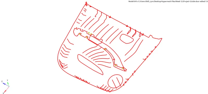
Free edges on the model.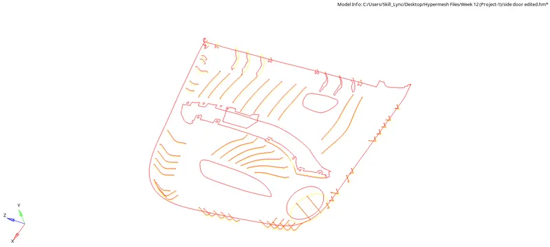
Free edges with non manifold lines. - Conclusion: In conclusion I would like to state that, this project helped get a better review of all the Meshing steps and how to counter a particular problem, be it Quality clearing or even the Geometric clean up.