Week 12 - Project-1
OBJECTIVE:
- To mesh the given component i.e side door with all the quality parameters.
- To assign the thickness to all the components.
GENERAL TRIVIA ABOUT SIDE DOORS :
A car door is type of door, typically hinged, but sometimes attached by other mechanisms such as tracks, in front of an opening which is used for entering or exiting vehicles. A vehicle door can be opened to provide the access to the opening, or closed to secure it. The doors can be opened manually, powered electronically. The exterior side of door is made of steel or other material like the rest of the vehicle's interior. Door panels serve as an interface between the interior of the car and the inner workings of door, between vehicle occupants and the door. They are expected to design a variety of design specifications regarding safety, asthetics and functionality. In addition they are expected to continue the material theme of dashboard and pillars while concealing electrical and mechanical components for operating locks, windows and other features. The door panel has evolved from a simple two part system of latch and simple winding mechanism to a more sophisticated enclosure. Doors currently have an inner width panel consisting of electonic windows, central locking system and speakers. These panels typically consist of a foamed core covered with either textiles or plastics.Door panels are expected to meet one of the toughest type of requirements amoung ineterior car components. These panels should be designed to withstand and channel loads into the body of the car while being thin. These loads could be horizantal and vertical in nature, like the force applied on openeing or closing the doors while leaning or resting on them or while stepping on the armrest to access the roof. Conventionally door panels consisted of Polyvinylchloride (PVC) foamed core with appropriate textile fabric coverings.
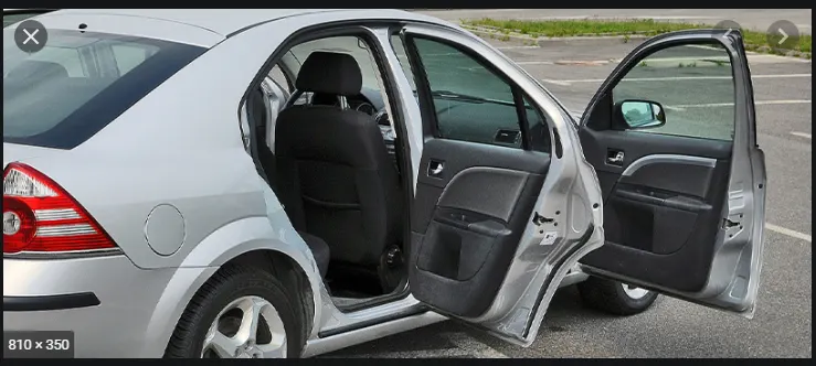
Fig(1).
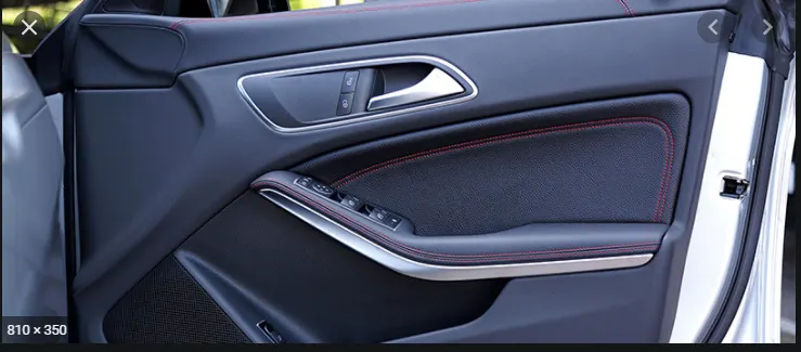
Fig(2). Interior side of a sidedoor.
CAD MODEL IMAGES:
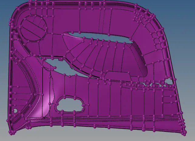
Fig(3).
PROCEDURE :
- The entire sidedoor has to be meshed and assigned thickness for the surfaces. The side door consists of ribs,circular surfaces. Sidedoor is a plastic component,so the thickness varies along the entire length.The entire process can be split into Three main phases, they are Geometry cleanup of the model and midsurface extraction, Meshing of the model with all the given quality parameters, Assigning the thickness to the model.The three phases are explained as below,
- GEOMETRY CLEANUP OF THE MODEL AND MIDSURFACE EXTERACTION :
- The basic prelimnary step is to import the model and geometry clean up of the imported model.
- To import the model, select import options and select the model and click on import.
- Set the model to topo mode, topology mode displays how the surfaces are connected to each other. The model will appear as shown in the below image,
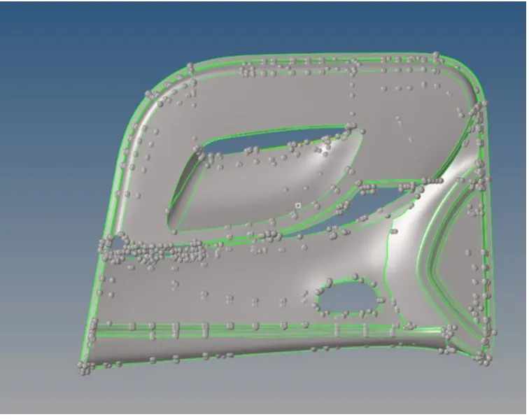
Fig(4). Model in topo mode
- The model will be in STEP/IGES/SOLIDWORKS format before importing to it in hypermesh.
- Once the model is imported into the hypermesh GUI, the next step is to clean the geometry of the model.
- Some surfaces may get auto deleted while importing, Recreate the surfaces using suitable options present in the Geomerty section.
- Check for any duplicates present in the model, if found delete them.
- Now the midsurface can be extracted from the model manually as the thickness varies along the surfaces.
- The part consists of a central base whose thickness is 2.8 mm and the rest of the features are of varying thickness.
- The part have some solid features which have complex geometry which are unsuitable for 2d meshing.
- There are strengthing ribs of varying thickness which we have to extract accordingly.
- There are some geometrical erros and free edges which we have to fix before meshing.
- The midsurface has to be extracted manually from the component, a new collector should be added and the midsurface have to be extracted for the central base.
- The rootpath is geometry-surface edit- offset- select surface(duplicate it to the current component)-specify the value of thickness-check the direction-click offset. The surface will be generated,
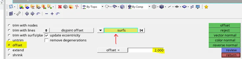
Fig (5). Surface edit panel
- Various features such as ribs can be created using midline extraction method, or offseting manually and then extending the ribs to the surface.
- The two methods are explained as shown below:
- Using midline method:
- In this method select the edges of the model as shown in the figure and genrate the midline for it.
- Trim this midline on the surface using surface trim options.
- Create the required surface by using this two lines.
- The rootpath is Geometry-Lines-Midlines option-select the edges of the ribs-click on middle mouse button, the line will be generated.
- Now goto surface edit-surface trim with line- select the central base surface-select the line-select the normal to the plane option - click ok, the second line will be genrated,
- Now goto surfaces-ruled-select the lines-click on the middle mouse button, the surface will be generated.
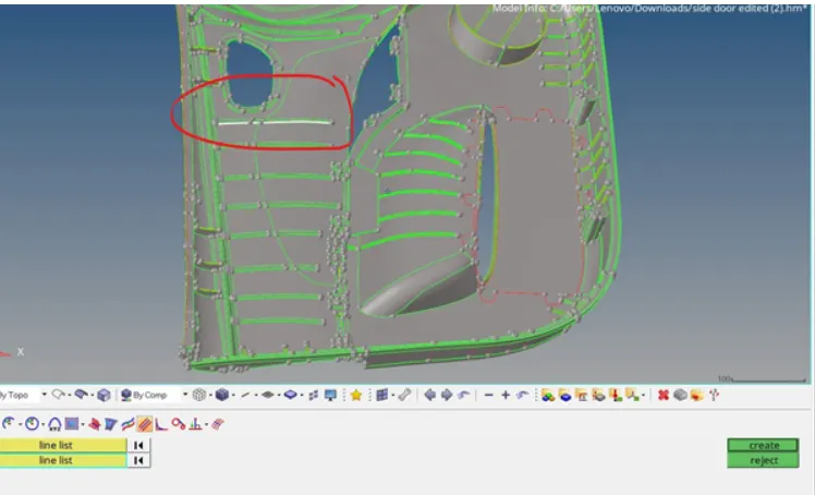
Fig(6). Selection of lines for midline

Fig(7). Trim the surface using lines option

Fig(8). Create the surface using both the lines
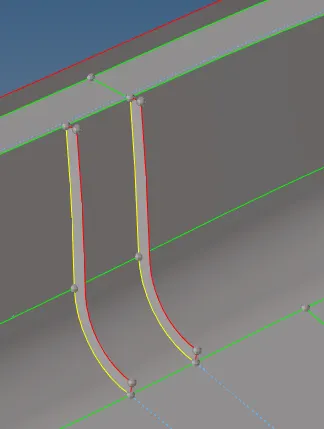
Fig(9). Ribs created using midline method
ii. Using Offset option and extending the rib to the surface:
- Goto surfaceedit-Offset-select any side of rib(duplicate the surface to the current component)- specify the distance- click on offset, the surface will be generated,
- Now goto surface edit-extend- select the surface- select target surface-click on extend. The rib will be generated.
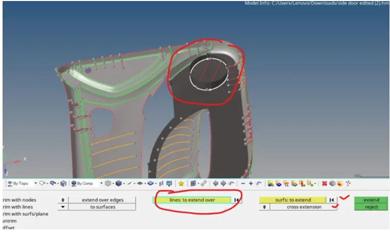
Fig(10). extend options
- Repeat this procedure for all the ribs present in the model. The midsurface will be as shown in the below figure,
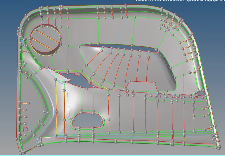
Fig(11). Final midsurface
2.MESHING THE MODEL WITH THE GIVEN QUALITY PARAMETERS :
- The next step is to mesh the model as per the quality parameters. Before meshing the model, We have to specify the quality parameters.
- The quaity parameters have to be entered in the criteria file settings in preferences option.
- The below is the set of images explaining these steps, The rootpath for quality parameters is preferences- Criteria file settings,
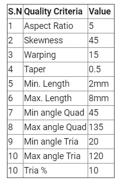
Fig(12). Given quality criteria
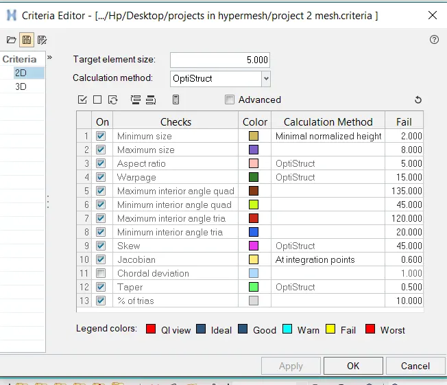
Fig(13). Criteria file editor
- Once all the quality parameters are filled, the model is ready to mesh. The meshing has to be done surface by surface to get a better mesh flow and quality.
- To perfrom 2d meshing on the model, Select 2d-automesh-specify element length- click on mesh, Here the target length is 5 and the type of elements are mixed.
- The mesh an be enhanced by using various tools in the quality index available in the 2d panel, many tools are available to enhance the quality of the mesh and to improve the mesh.
- The following are some of the tools constantly used while meshing for fixing the quality of the elements,

Fig(14). 2d panel in hypermesh

Fig(15). Quality index panel

Fig(16). Automesh panel
- Place node - This tool is used to adjust the nodal location of the element.
- Smooth - This tool is used for uniform mesh flow.
- Drag tria - This tool is used to eleminate tria elements from the surface if posiible and also to manipulate the location of the tria elements.
- Swap edge , this tool is used to change the location of the element.
- Element optimise, This tool enhances the element quality.
- Split quad, this is used to spli the quad element.
- Combine tria, As the name itself suggests this tool is used to combine two tria elements.
- Smooth option is also available in 2d outside the quality index panel, The following is the image of the smooth panel present in 2d.

Fig(17). Smooth panel
- While mehsing the trias have to be eliminated from the surface as the trias are more stiffer when compared to quad elements. The tools such as swap edge, drag tria, combine tria help to remove trias.
- Also rotating quads are also not prefered while meshing because they deviate the applied force in a unwnated directon resulting in the inaccuracy of the solution. Instead trias are prefered in that region.
- There are some ground rules while handling these trias, they are listed as follows:
- No trias should touh each other.
- Trias facing in the opposite direction should be eliminated.
- There shouldnot be back to back trias.
- Trias shouldnot be present near the surface of the holes.
- Trias should not be present in the fillet regions.
- Trias concentration shouldnt be more, there should be considerable distance between them. The following are some of the examples of tria region that have to be eliminated,
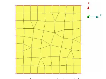
Fig(18). Bad mesh quality
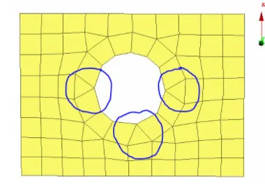
Fig(19). Trias near holes should be eliminated
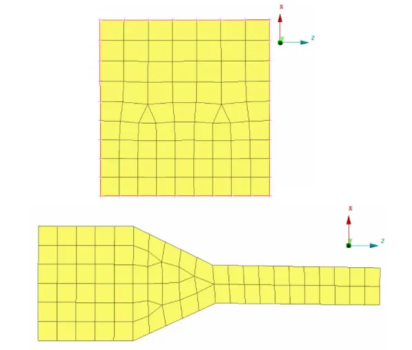
Fig(20). Better mesh flow
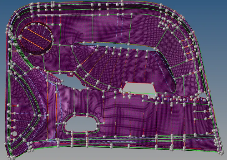
Fig(21). Mesh generated on the surface
3. ASSIGNING THE THICKNESS TO THE SURFACES:
- For the surfaces, thickness has to be assigned. This can be done by creating the property and assigning it to the component as shown in the below figure,
- The ribs have to be moved to different collectors and the thickness have to be assigned as below,
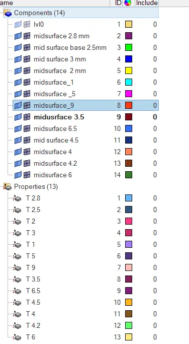
Fig(22). Component and thickness tab
RESULT :
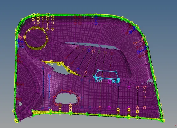
The image of the side door meshed fe model is as shown below,