SHELL MESH AND MID SURFACE EXTRACTION ON SIDE DOOR INNER PANNEL
AIM:-To perform shell mesh on the side door inner pane.l
PROCEDURE:-
- Import the model by going to import and select import cad and select the format of the file and click import.
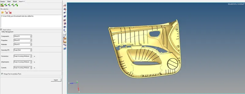
- Then we need to give the parameters to the component for meshing.
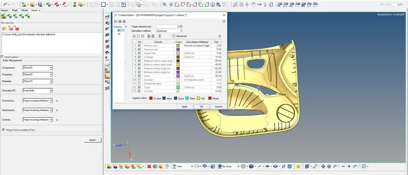
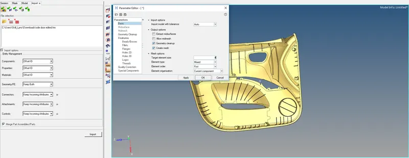
- To give the parameters we need to go to preferences and select criteria file setting and give the conditions of mesh-like target size.
- Here we need to specify the quality criteria given to the component.
- Open the parameter and give target element size and press ok.
- To save the criteria and quality we need to select the save button.
- As the geometry is complex so we need to split the component.
- To split, we need to select the node and then we need to specify the axis and we need to select trim.
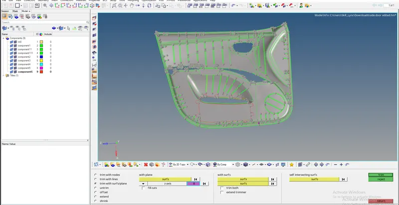
- After that, we need to organize the model into two different components.
- To organize we need to go to tools and select organize and select surfaces and move the surface to a different component.
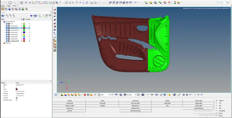
- After that, we need to measure the dimensions of every part and we need to extract the mid surface.
- To measure the dimension we need to go to the geometry and then go to the surface panel and select dimensions.
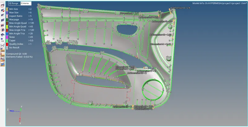
- Then after we need to extract the mid surface
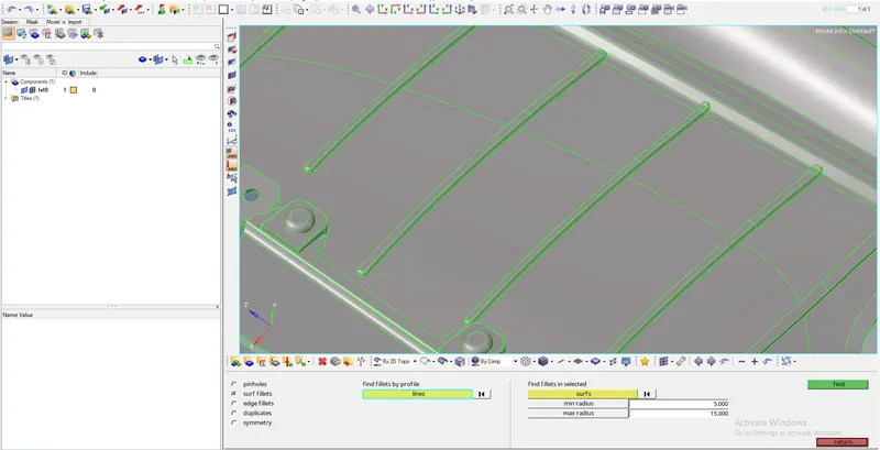
- To defeature we need to go for defeature in surface option in geometry and then we need to select the surface fillets and we need to specify the min and max radius
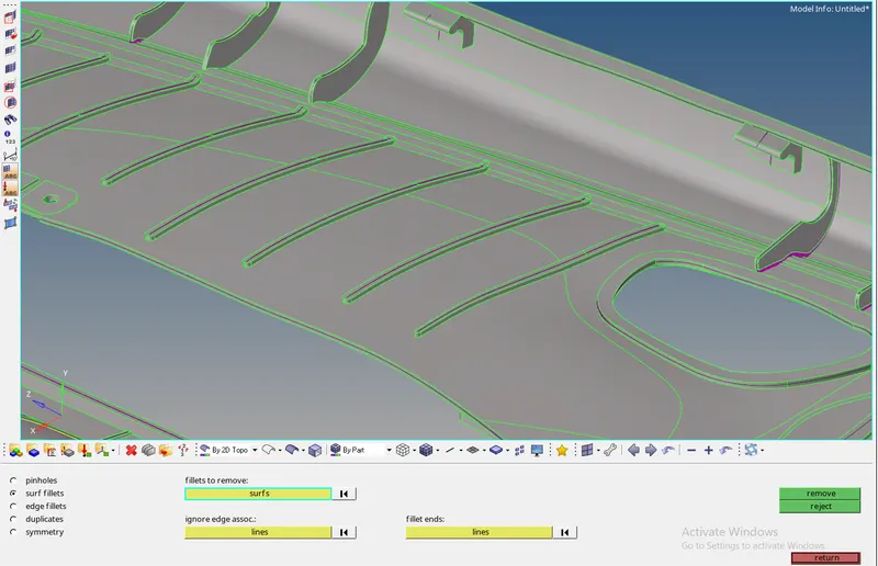
- To extract the mid surface we need to go to geometry and select the mid surface in the column of surface
- We need to change the options of auto mid surface we need to goto extract option and we need to set the option as skin offset
- If this mid surface is not working properly then we need to select the offset option
- To offset we need to select the surface and duplicate the surface and give the offset distance
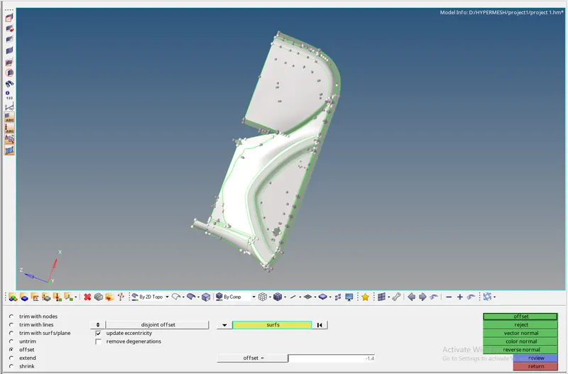
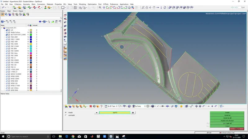
- The tools which are used majorly in extracting the mid surface are
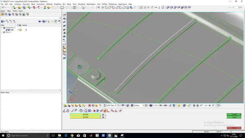
- Select the second line list and from the middle line
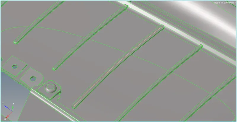
- Then we need to use trim the line with the surface and form a new surface

- And the other option is to take the middle of the surface
- To take the middle between the surface we need to go to auto mid and select the final edit tool and select one surface and other surface and press enter

- Then we need to extend the surface to connect them properly


- By these options, we had extracted the mid surface
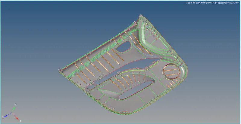
- After extracting the mid surface we need to goto geometry clean up and clean the geometry
- For geometry cleanup, we need to go to geometry and select quick edit

- To split the surface we use split with node and split with line
- To reduce the concentration at the hole we need to select the washer
- To unsplit surface, we need to use unsplit surface
- To paste or to trim we use toggle edges
- The raw geometry has the missing surface to fill the surface we need to use the filler surface
- To delete surface we use delete surf
- To replace or combine the points we need to use replace point
- To add or remove a point we need to use the add/remove point
- Mid surface after cleaning the geometry
- After cleaning geometry we need to mesh the surface
- To mesh we need to select the surface and give the target element size and mesh the part
- To alter the mesh we need to change the number of nodes
- We need to mesh the part by using auto mesh
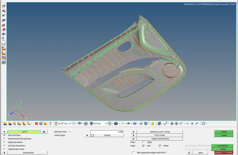
- The major option for doing meshing is to perform the mesh if any flow issue is there we need to mesh

- For quality issues, we use the quality index

- PLACE NODE to move the nodes freely to reduce the quality
- Element optimizer will optimize the element quality
- Smooth will smooth the mesh flow and adjust with respect to the min and max size
- Split edges are used to split the edge of the quads
- Drag tria which used to drag the trias from one point to another point
- combine trias it will combine two tria in a quad
- Parts that are been meshed

- It will reduce the quality and gives the mesh
- But it does not give the option to change the number of nodes

- It refines the mesh and gives good mesh flow
- But by using this we will have lot of connectivity issues

- F3 is used to paste the nodes of the mesh which are not in connectivity

- It is used to refine the size of the mesh when it is been distorted

- If the mesh has quality issues it will cover all sort of errors
- Component after completion of mesh
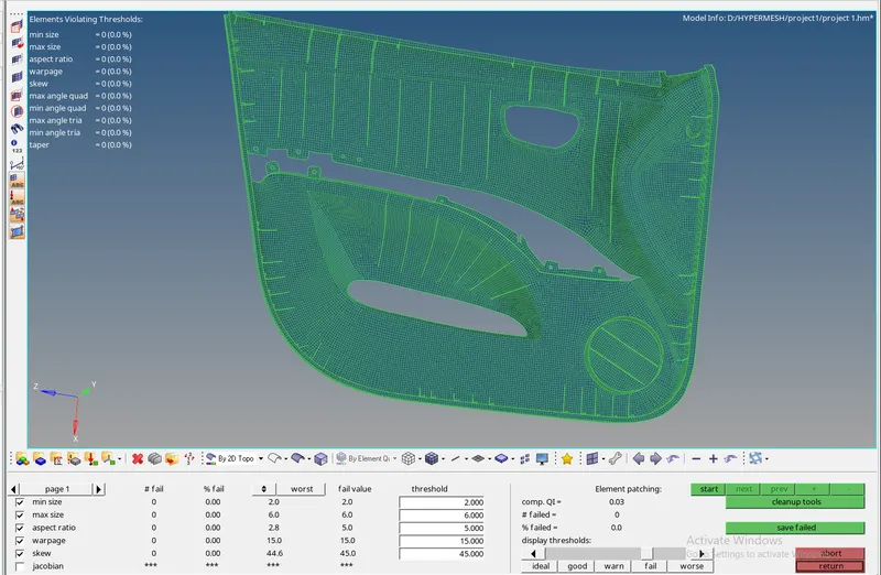
- And after meshing we need to assign the thickness of every subcomponent
- To assign we need to create the property and assign thicknesses
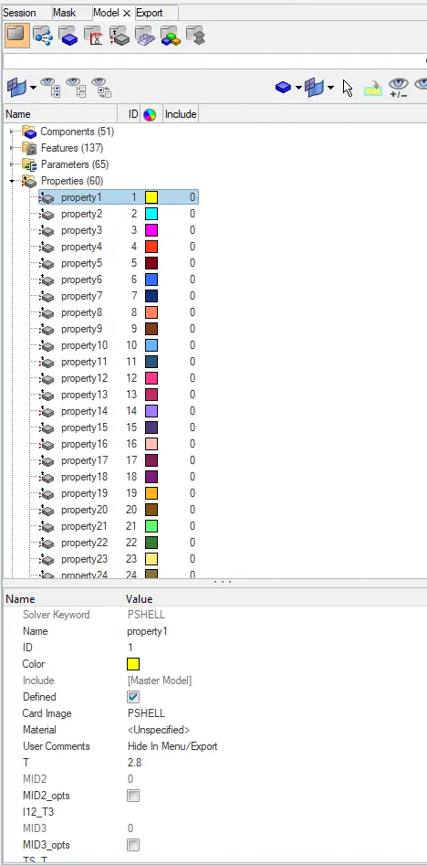
- And another method is to assign the thickness automatically
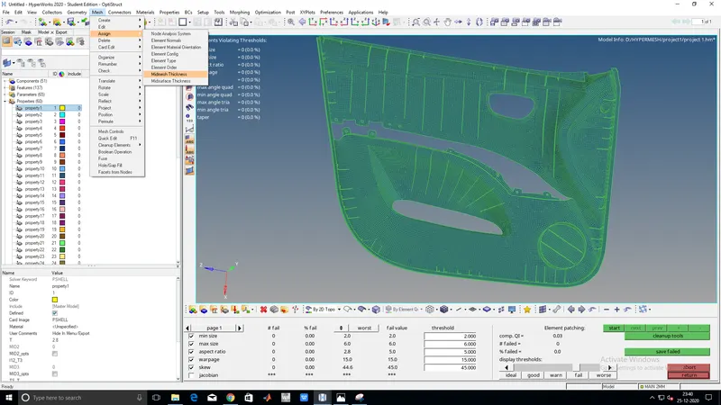
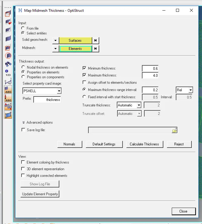
- It will assign the thickness automatically
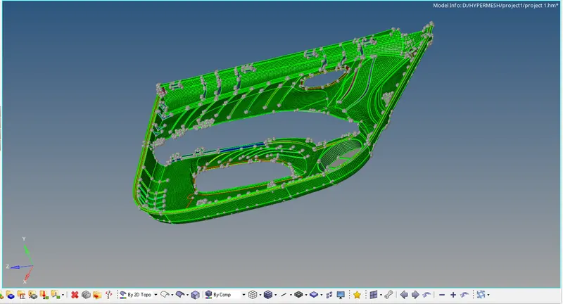
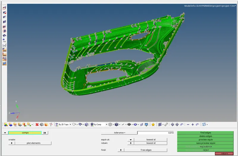
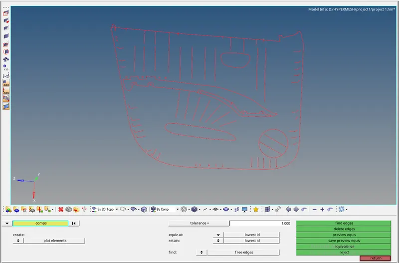
- The final evaluation is to check free edges

CONCLUSION:-
- We must clean the geometry of mid surface before entering into the mesh
- We must avoid trias that are facing opposite and back to back
- We must provide a perpendicular construction line that enhances the quality of the mesh
- Avoiding trias in a certain area is difficult then we must give space between them
- While comparing tria vs quality, we must give importance to quality first
- By understanding the symmetrical structure of the part we can minimize the time