Week 12 - Final Project - Modelling and Analysis of a Datacenter
Objective:
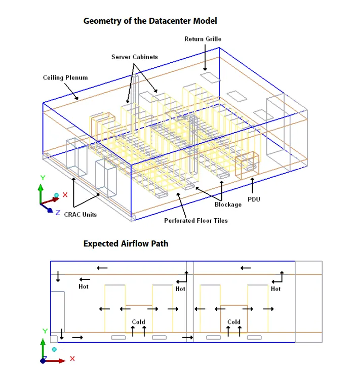
To create a model of the data center which includes computer room air conditioning units (CRACs), server cabinets, power distribution units (PDUs), and perforated floor tiles in the data center. and study the flow distribution and behavior of server stacks in the data center
Problem description:
This tutorial considers a 1200 sq. ft. datacenter with a slab-to-slab height of 12 ft. The data center consists of a 1.5 ft underfloor plenum and a 2 ft ceiling plenum. The CRACs discharge cold air into the underfloor plenum. The cold air enters the main data center space mainly through the perforated floor tiles and returns back to the air conditioning units. The cooling load, as summarized below. The size and Capacity of Heat Sources in Datacenter correspond to the heat output from the server cabinets and the PDUs. A PCB board, library files, and traces are imported to create the model. The model is first solved for conduction only, without the components, and then solved using the actual components with forced convection.
|
Heat Source |
Size |
Power |
|
Server Cabinet |
2 ft x 3 ft x 7 ft |
3000 W |
|
High Density |
2 ft x 3 ft x 7 ft |
7000 W |
|
PDU |
4 ft x 2 ft x 5 ft |
3600 W |
Datacenter:
A data center is a building or a dedicated space within a building, or a group of buildings used to house computer systems and associated components, such as telecommunications and storage systems.
Since IT operations are crucial for business continuity, it generally includes redundant or backup components and infrastructure for power supply, data communication connections, environmental controls and various security devices. A large data center is an industrial-scale operation using as much electricity as a small town.

Geometry:
1. Create the Geometry of the cabinet with the given dimensions
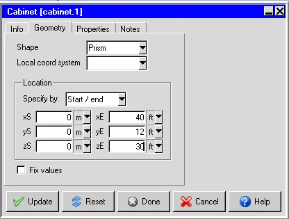
2. Pictures of cabinet
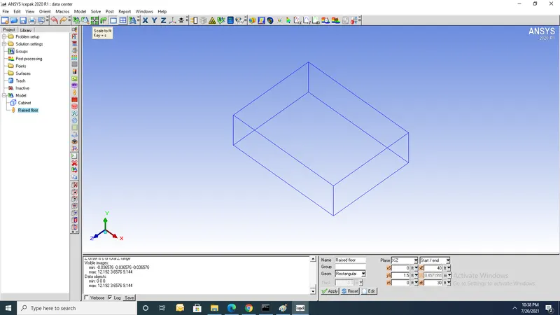
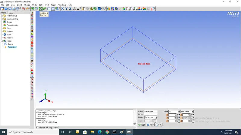
3. Create geometry of the Raised floor
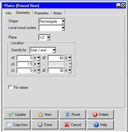
4. Picture of Raised floor
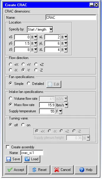
5. Geometry of CRAC
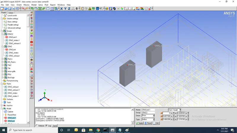
6. Copy CRAC and translate to get another CRAC2 together to form a group CRAC
7. Create racks with a heat load of3000W
8. Create copy of racks translated by x=7ft
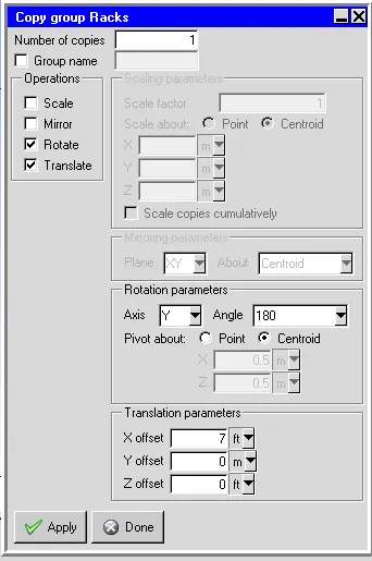
8. Picture of racks
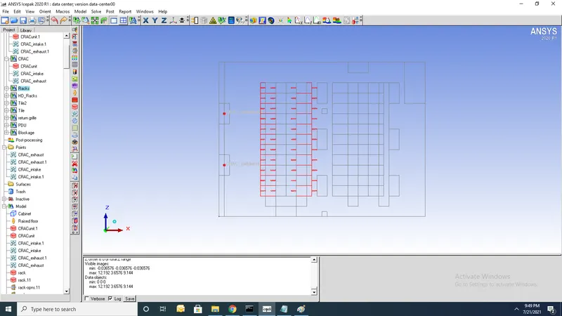
9. Create HD Racks with a heat load of 7000W
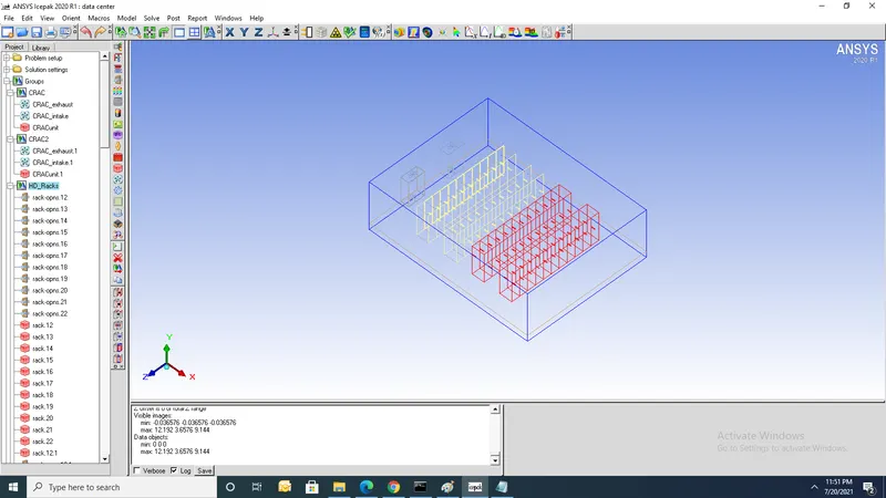
10. Create Tiles with the geometry
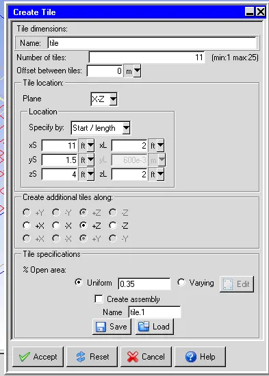
11. Picture of tiles(n=11) is shown
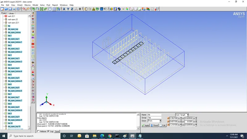
12. Copy Tiles and Translate in x-direction to get another set of Tiles
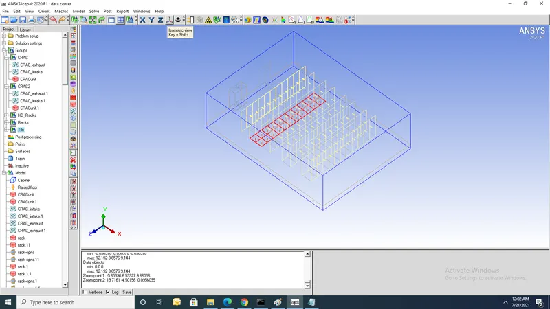
13 Similarly create Tiles on another side
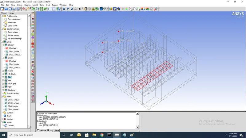
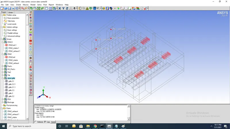
14. Create grills for flow to be exhausted
15. Create PDU with a heat load of 3600W
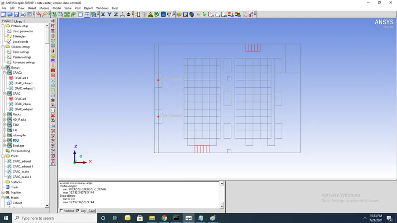
Meshing:
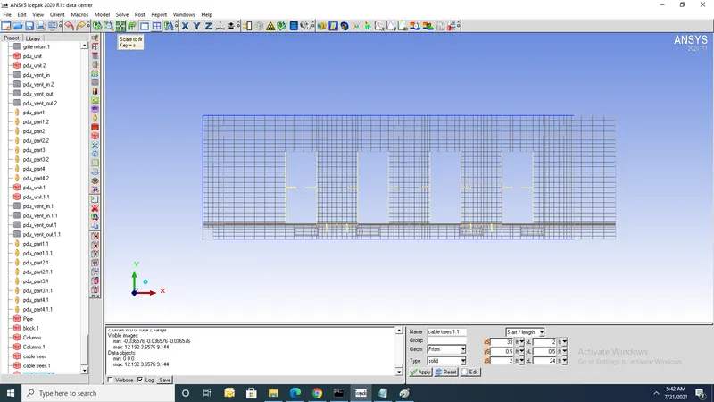
1. Total Number of elements=141917 and Total number of nodes=167936
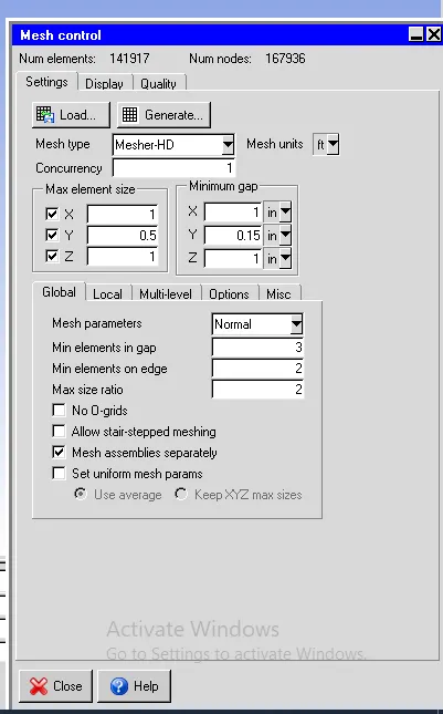
2. Do mesh separately for CRAC and give x,y, and z count
3.Cutplane along x-axis
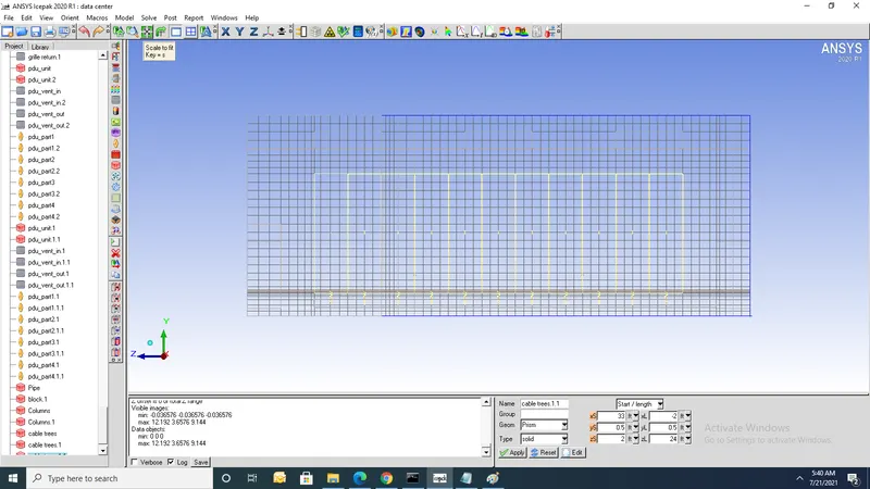
4. Cutplane along y-axis
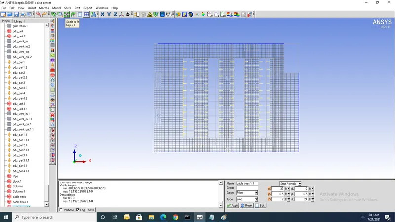
5. Cutplane along z-axis
Numerical setup:
1. solve for velocity,Pressure, temperature and species
2. Flow has an inlet/outlet (Forced convection)
3. Set the flow regime as turbulent
4. Turbulent model (Zero equation)
5. ignore heat transfer due to radiation
6. Apply steady state
7. Enable gravity in the negative y direction (g=-9.81)
8. Natural convection Ideal gas laws of pressure=101325 N/m2
2. Solution settings
- set no of iterations 500 and convergence criteria for energy to 1e-12
- Temperature Linear solver: F cycle is selected for Type Enter 1e-6 for both the Termination criterion and Residual reduction tolerance
- Select Double for the solver Precision.
Contours:
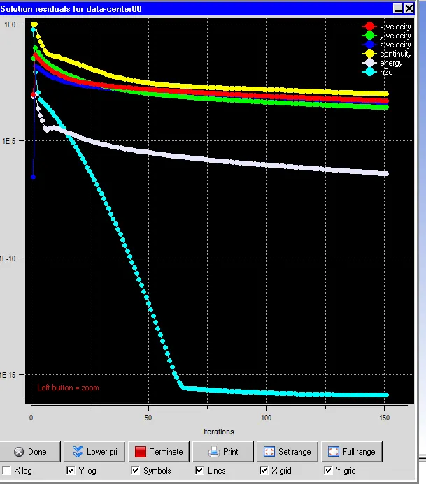
1. Residuals
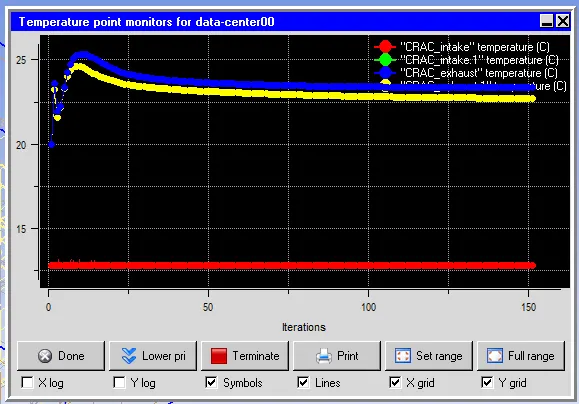
2.Monitor points
Temperature contours:
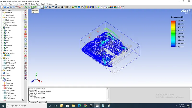
1. From contours it shows that min temp=12.77oC and Max temp=29.7oC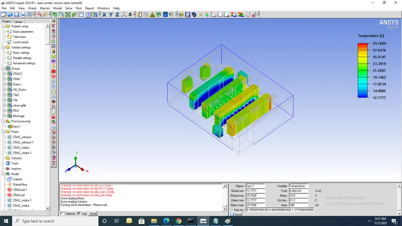
Cut plane contours:
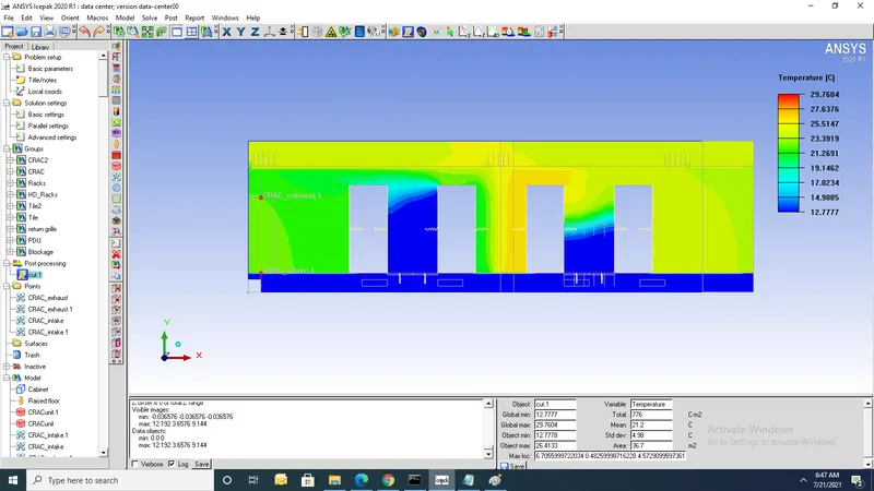
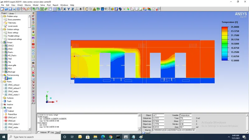
Contours of partices:
1.Flow of particles are shown in fig