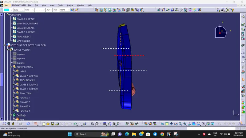
Week 12- Final project
- FINAL PROJECT - DEVELOPMENT OF DOOR TRIM PANEL
DESIGN PROCEDURE -
1) Class A surface check.
2) Creating tooling axis.
3) Draft analysis on Class A surface.
4) Creation of Class B surface.
5) Creation of Class C surface.
6) Final trimmed surface.
7) Convert surface to solid.
8) Creation of flanges and engineering features by folllowing master sections (Heat stakes).
9) Creation of additional engineering features (Dog house & locators).
10) Assemble push pin with dog house.
DOOR TRIM PANEL -
A) CLASS A SIDE B) CLASS B SIDE
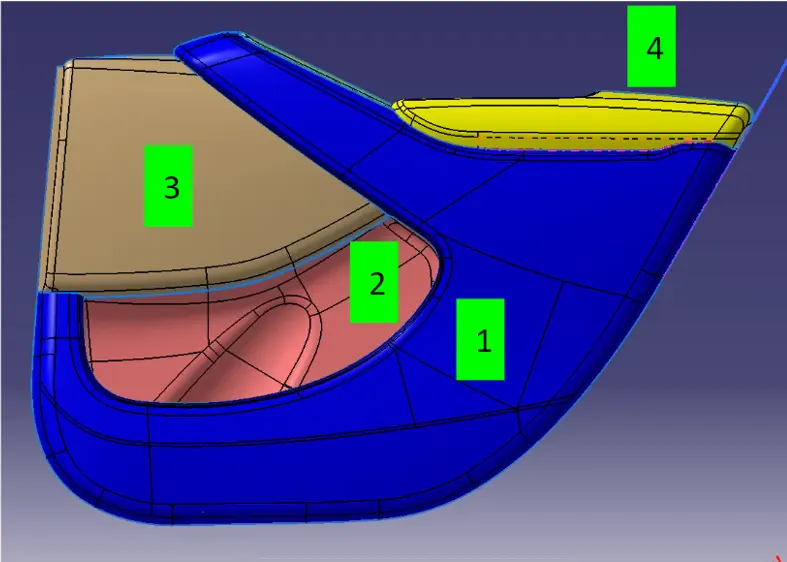
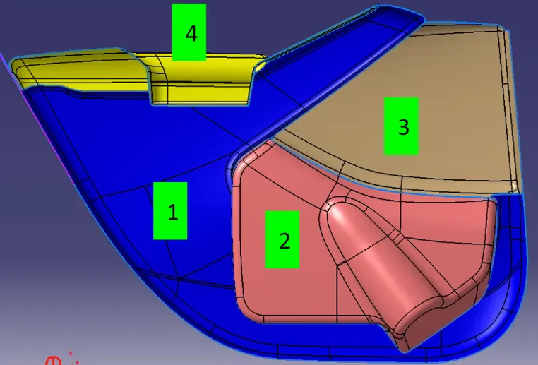
PARTS IN DOOR TRIM PANEL -
1) Lower Substrate.
2) Bottle Holder.
3) Map pocket.
4) Arm Rest.
We are following same design procedure for all above four parts.
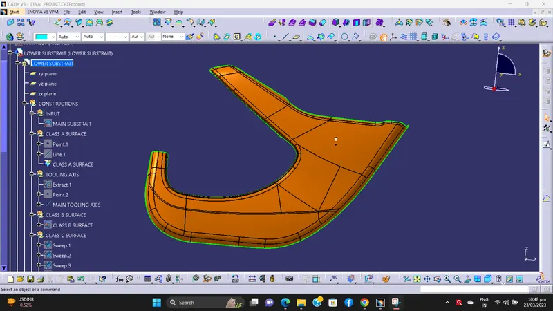
1) Class A surface check -
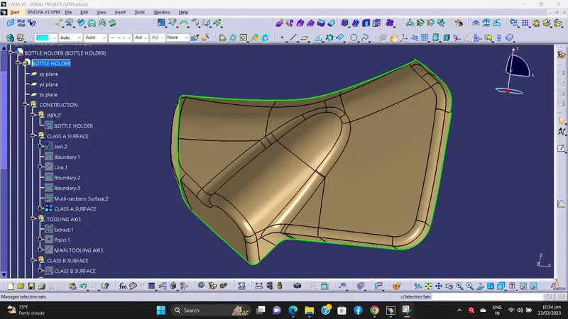
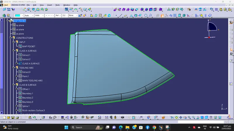
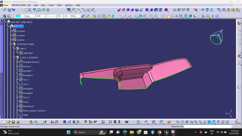
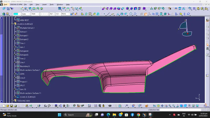
This surface is provided by styling team. This Class A surface is check by using boundary command, if there is irregularities then it is clear by using join command.
Then by using publication tool Class A surface is published.
a) Lower Substrate -
b) Bottle Holder -
c) Map pocket -
d) Arm Rest -
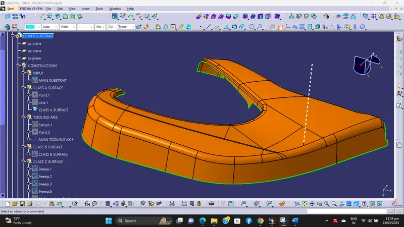
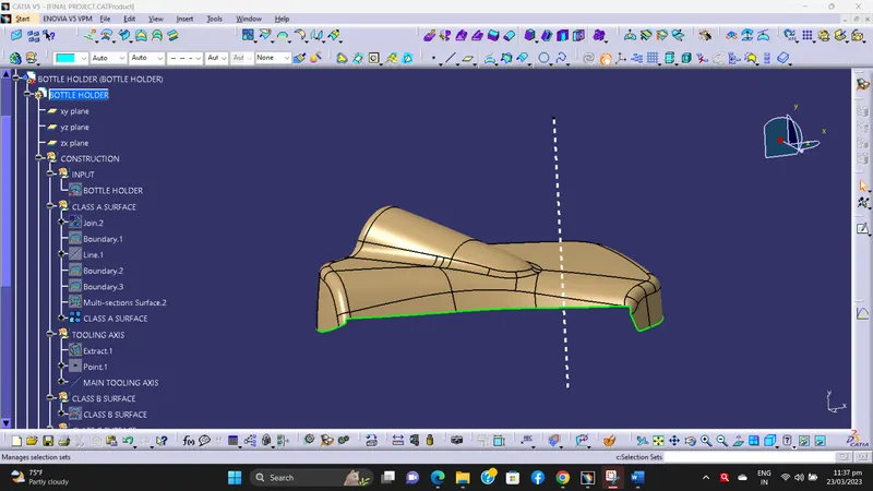
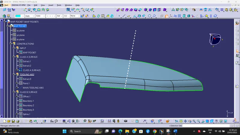
2) Create tooling axis -
In this project we used normal to the surface tooling axis as per our convenient.
Main tooling axis -
a) Lower Substrate –
b) Bottle Holder –
c) Map pocket –
d) Arm Rest -
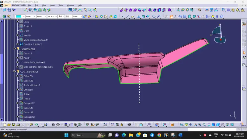
b) Side core axis for Arm Rest -
In the arm rest we also create side core tooling axis along with main tooling axis to perform the operation in Y direction.
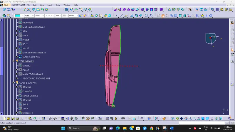
Then published tooling axis by using publication tool.
3) Draft analysis for Class-A surface -
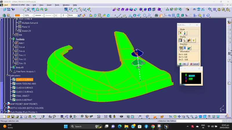
By changing the view mode to custom view, in the parameters – Material mode is selected. Then the feature of draft analysis is enabled.
Then the compass was activated and placed with the tooling axis by dragging the red pointer and then locked it.
Then, by selecting the quick analysis mode, the nominal value will be 3 degrees and checked for the components draft angle.
The green colour area shows that it satisfies the 3-degree draft angle.
If not satisfied then by using the running point tool the area is measured and then altered to get a successful draft for the created tooling direction.
a) Lower Substrate -
b) Bottle Holder -
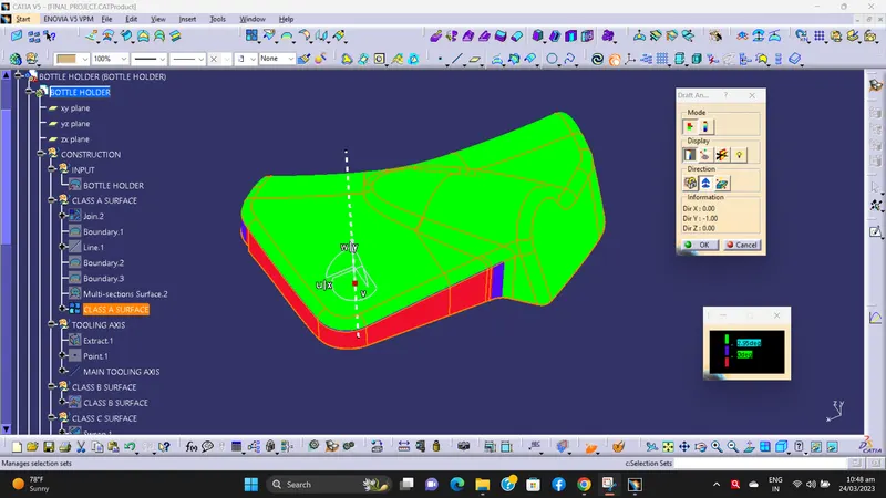
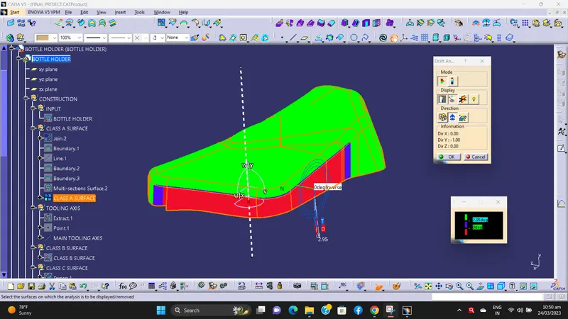
In above image, the RED colour show the Class-A surface is not cleare the draft analysis with 2.95deg.
There is the minimum 0 deg draft.
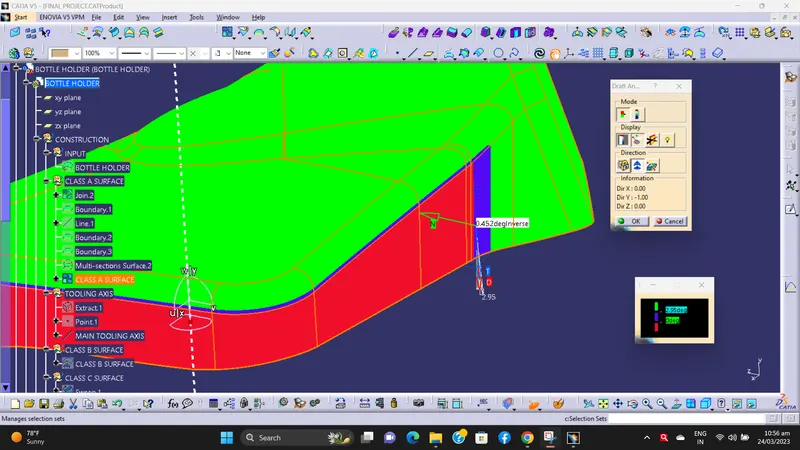
In above image, the BLUE colour show the Class-A surface is not cleare the draft analysis with 2.95deg.
There is the minimum 0.452 deg draft.
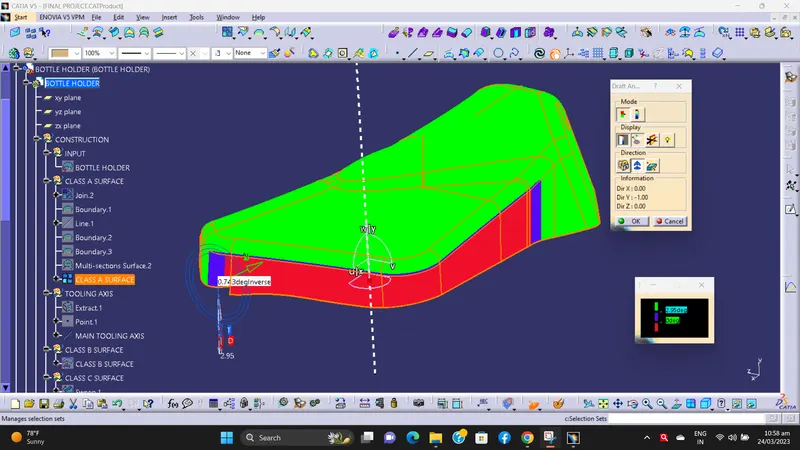
In above image, the BLUE colour show the Class-A surface is not cleare the draft analysis with 2.95deg.
There is the minimum 0.743 deg draft.
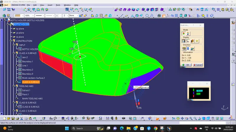
In above image, the BLUE colour show the Class-A surface is not cleare the draft analysis with 2.95deg.
There is the minimum 1.771deg draft.
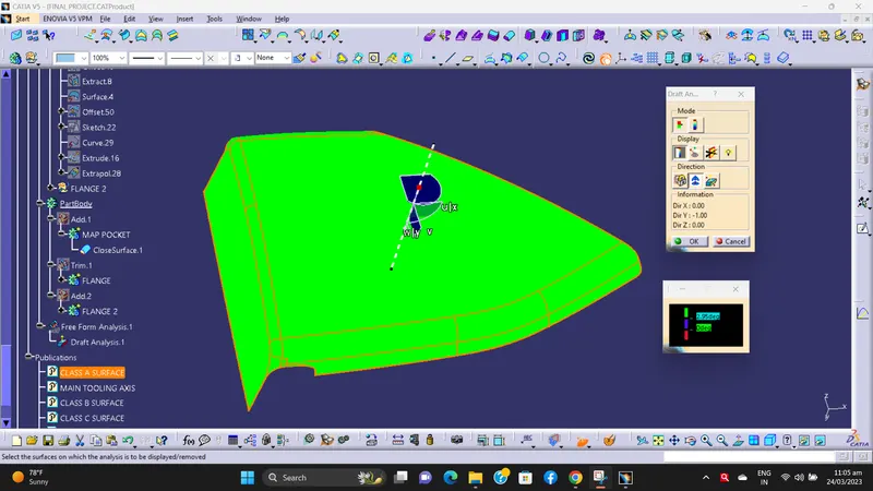
c) Map pocket -
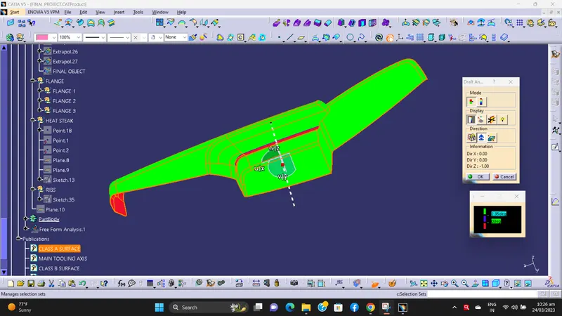
d) Arm Rest -
A) Draft analysis with main tooling axis -
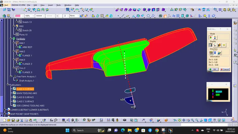
B) Draft analysis with side coring tooling axis -
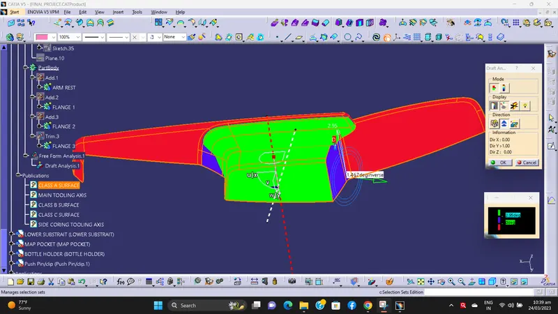
In above image, the BLUE colour show the Class-A surface is not cleare the draft analysis with 2.95deg for side core axis. There is the minimum 1.467 deg draft.
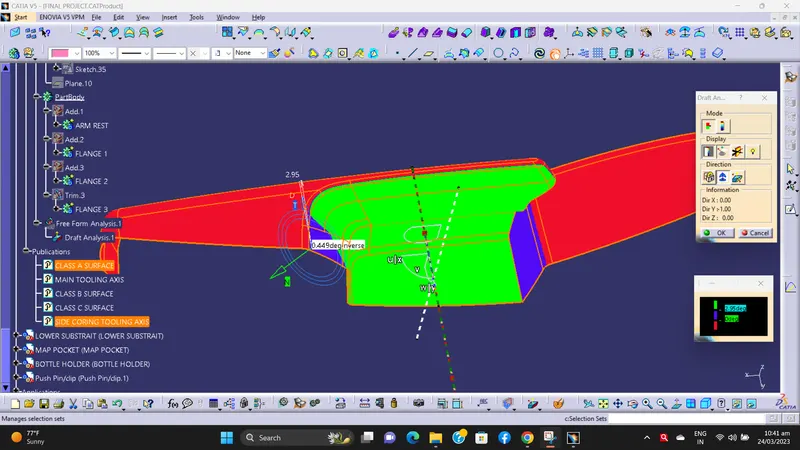
In above image, the BLUE colour show the Class-A surface is not cleare the draft analysis with 2.95deg for side core axis. There is the minimum 0.449 deg draft.
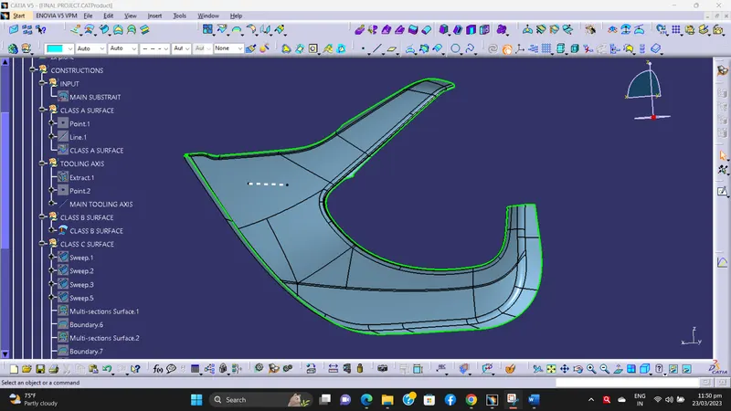
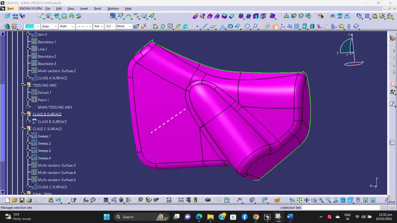
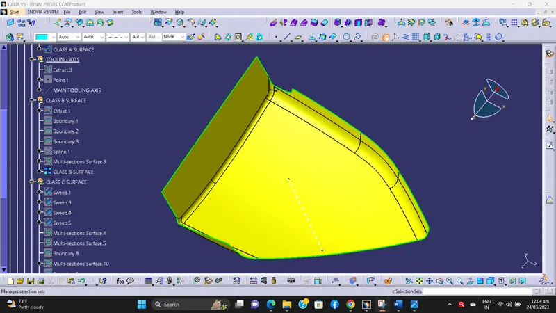
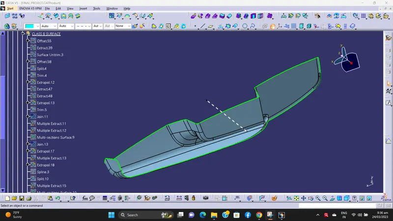
4) Creation of Class-B surface -
For creating the Class-B surface, we offset Class-A surface in downward direction by 2.5mm.
Then all the missing fillet patches or other surfaces are created by using multipale extract,extrapolate and trim command.
Finally, the required corners have been filleted by reducing the thickness value 2.5mm
Then published Class-B surface by using publication tool.
a) Lower Substrate –
b) Bottle Holder –
c) Map pocket –
d) Arm Rest -
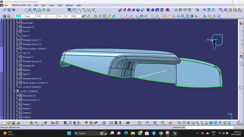
5) Creation of Class-C surface -
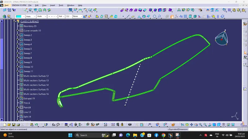
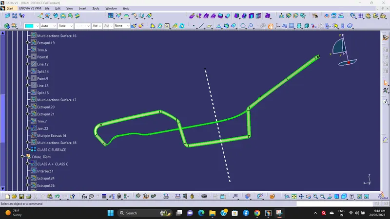
For the creation of Class-C surface, creating the boundary for Class-A surface.
Then by using the sweep command the surface was created by selecting respective boundary.
So get our Class-C surface.
After that we published Class-C surface by using publication tool.
a) Lower Substrate -
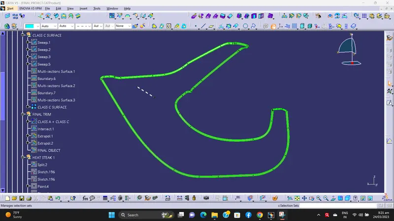
b) Bottle Holder -
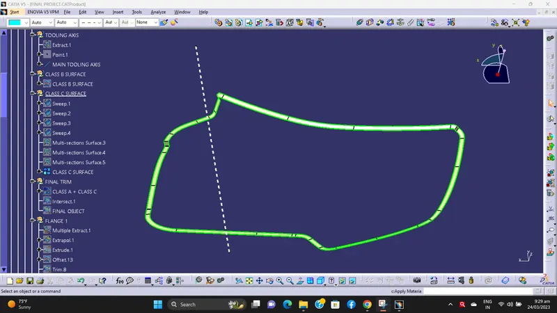
c) Map pocket -
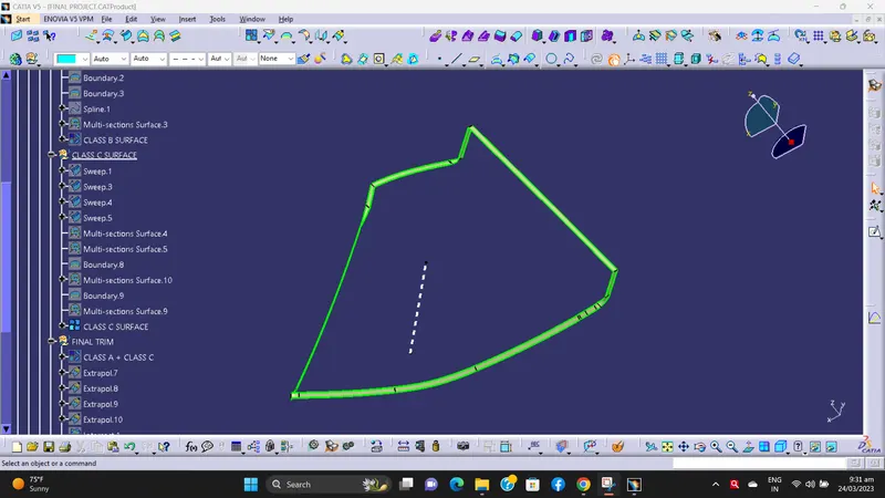
d) Arm Rest -
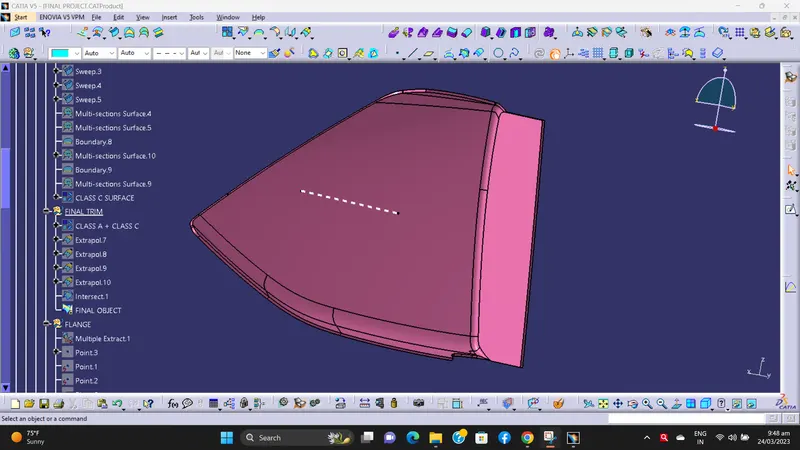
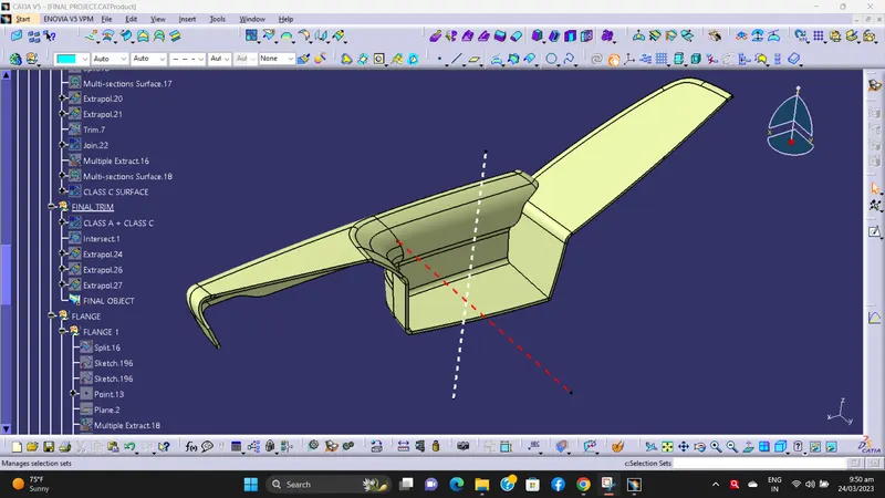
6) Final trimmed surface -
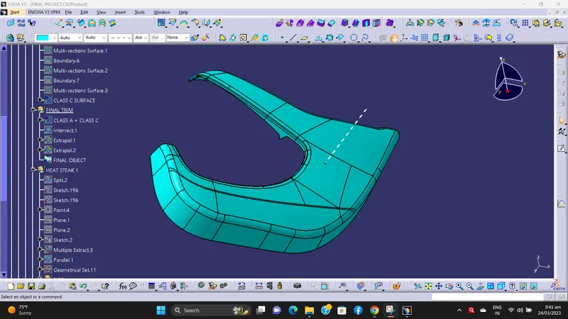
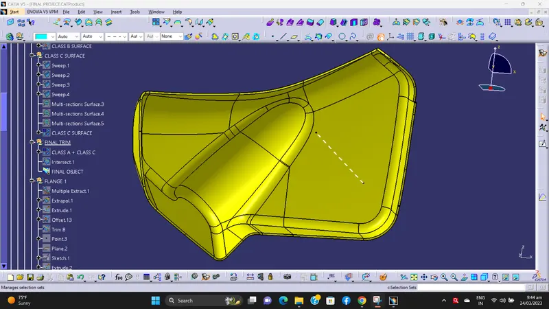
Now the Class–A surface is join with the surface which created by using sweep command.
Now this join is trimmed with Class-B surfaces.
We got required final trimmed surface.
Then published final trimmed surface by using publication tool.
a) Lower Substrate -
b) Bottle Holder -
c) Map pocket -
d) Arm Rest -
7) Convert surface to solid -
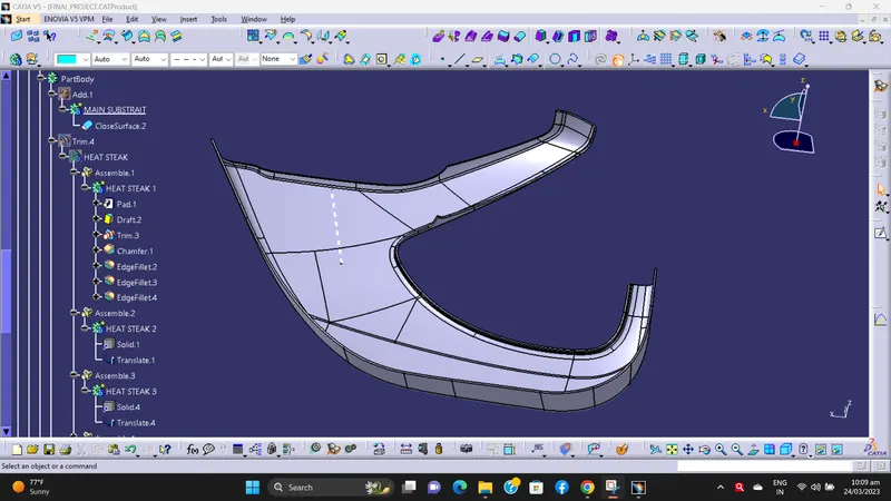
Now in part design workbench the final trimmed surface is converted into solid part by using close surface command.
a) Lower Substrate -
Solid Body -
Draft Analysis For Solid Body -
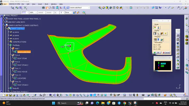
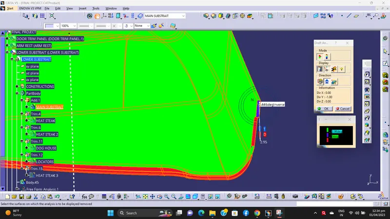
In above image, the BLUE colour show the Class-C surface is not cleare the draft analysis with 2.95deg for side core axis. There is the minimum 2.446 deg draft.
b) Bottle Holder -
Solid Body -
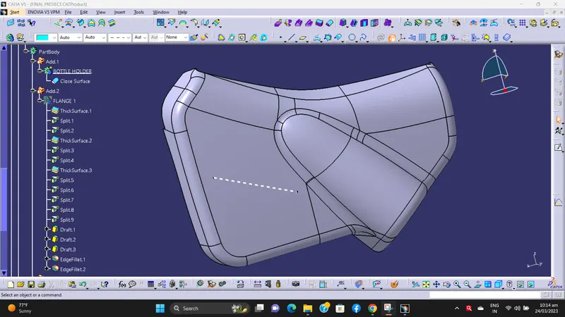
Draft Analysis For Solid Body -
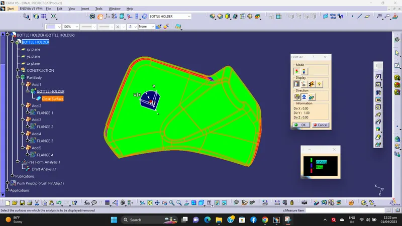
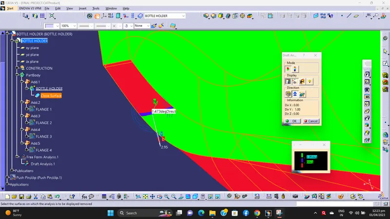
In above image, the BLUE colour show the Class-C surface is not cleare the draft analysis with 2.95deg for side core axis. There is the minimum 1.473 deg draft.
c) Map pocket -
Solid Body -
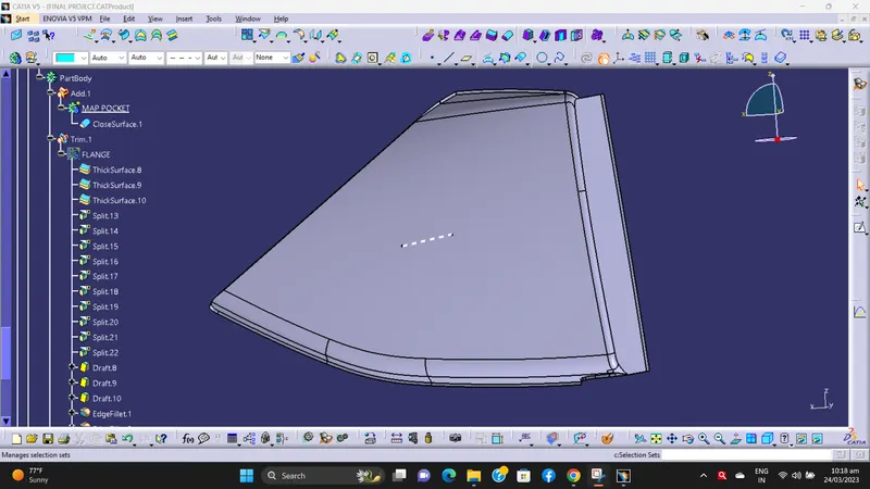
Draft Analysis For Solid Body -
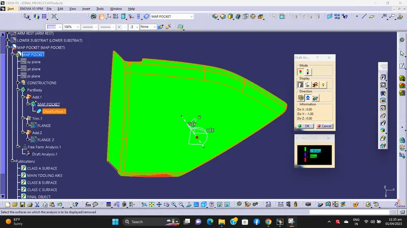
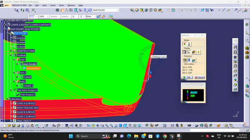
In above image, the RED colour show the Class-C surface is not cleare the draft analysis with 2.95deg for side core axis. There is the minimum -0.44 deg draft.
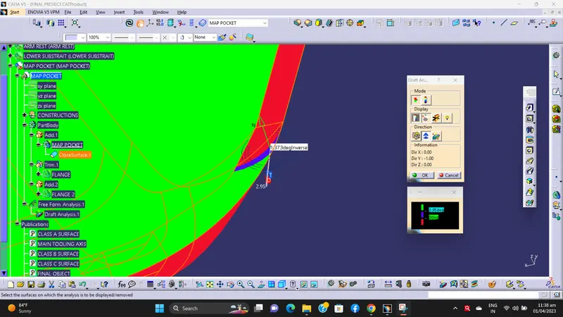
In above image, the BLUE colour show the Class-C surface is not cleare the draft analysis with 2.95deg for side core axis. There is the minimum 1.37 deg draft.
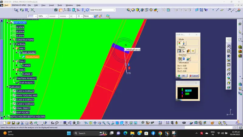
In above image, the BLUE colour show the Class-C surface is not cleare the draft analysis with 2.95deg for side core axis. There is the minimum 1.248 deg draft.
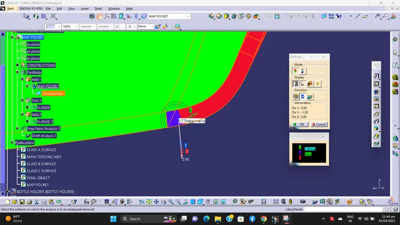
In above image, the BLUE colour show the Class-C surface is not cleare the draft analysis with 2.95deg for side core axis. There is the minimum 0.776 deg draft.
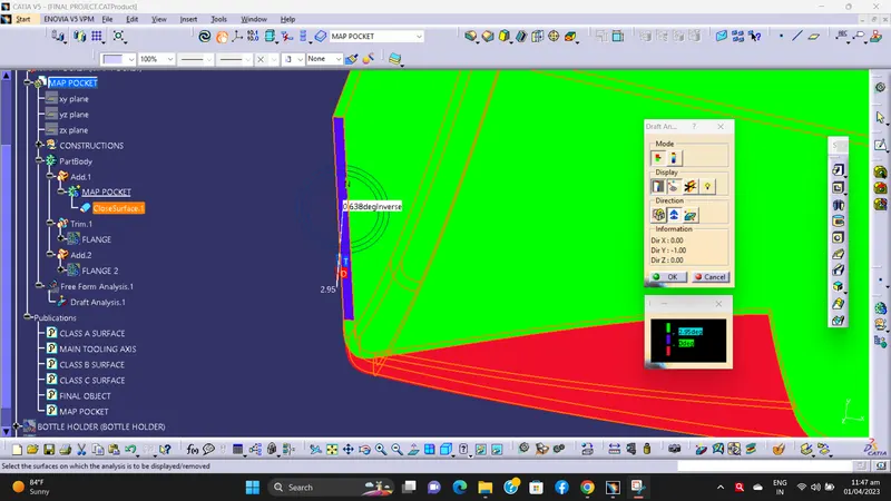
In above image, the BLUE colour show the Class-C surface is not cleare the draft analysis with 2.95deg for side core axis. There is the minimum 0.638 deg draft.
d) Arm Rest -
Solid Body -
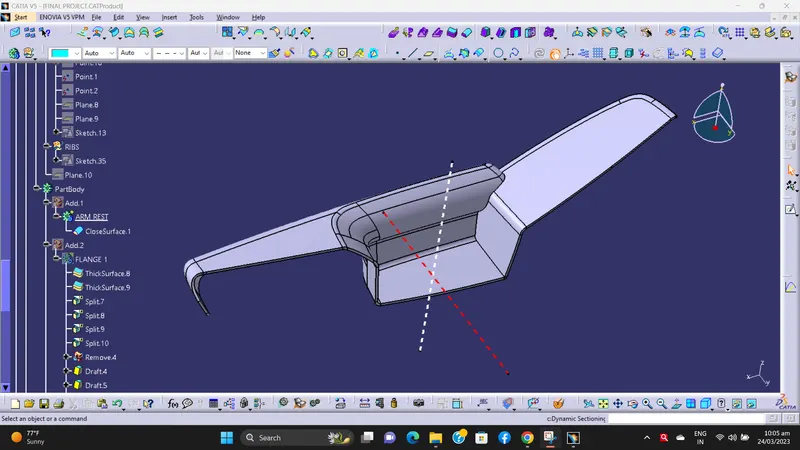
Draft Analysis With Main Tooling Axis For Solid Body -
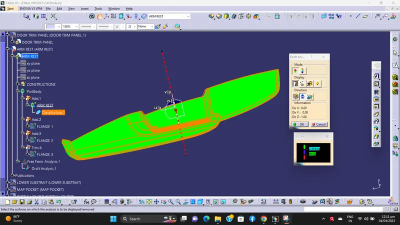
Draft Analysis With Side Core Tooling Axis For Solid Body -
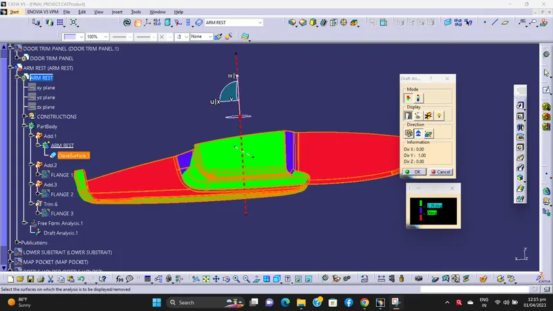
8) Creation of flanges and engineering features by folllowing master sections -
A) FLANGES -
By following master sections we are create flanges for Arm Rest and Map Pocket.
a) Arm Rest -
- Master Section for Arm Rest -
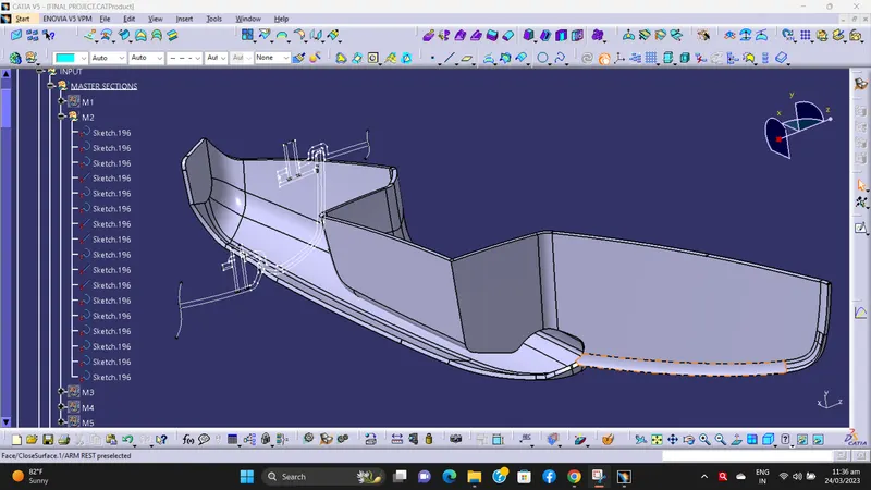
- Creation of flange -
FLANGE 1 -
Sketch 1 -
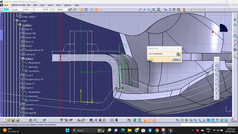
Sketch 2 -
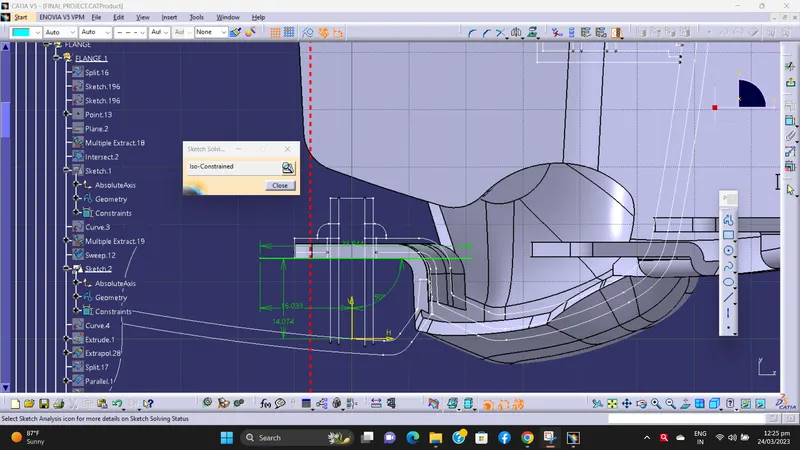
Sketch 3 -
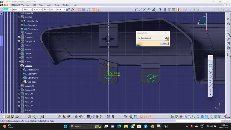
Surface oprations -
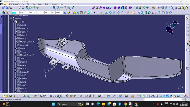
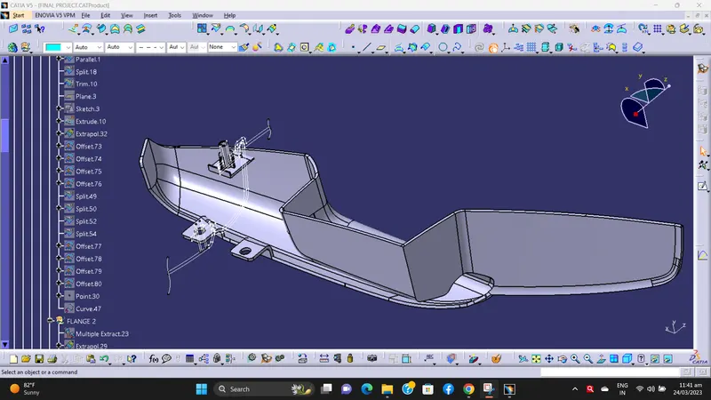
For solid body we are use thicken command in part body workbench.
For edge fillet we are following the master section.
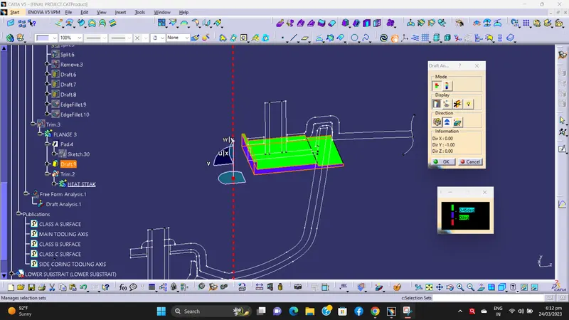
We are given 0.5deg draft for outer faces of flange.
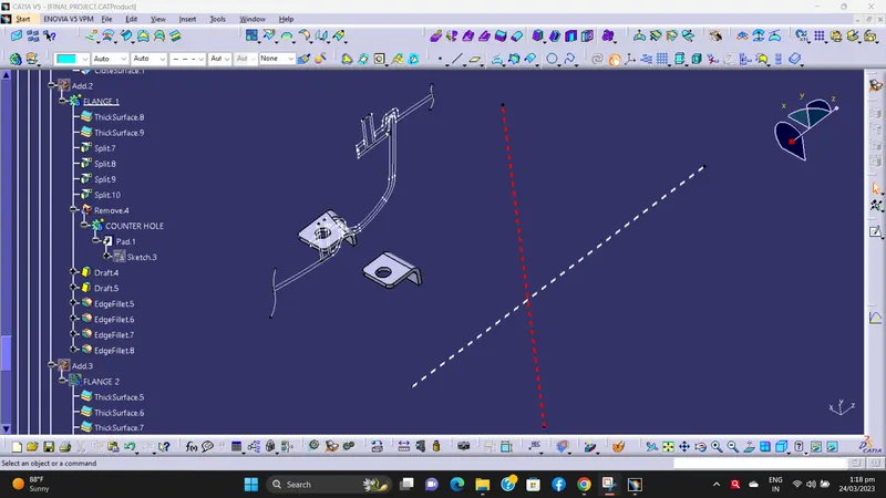
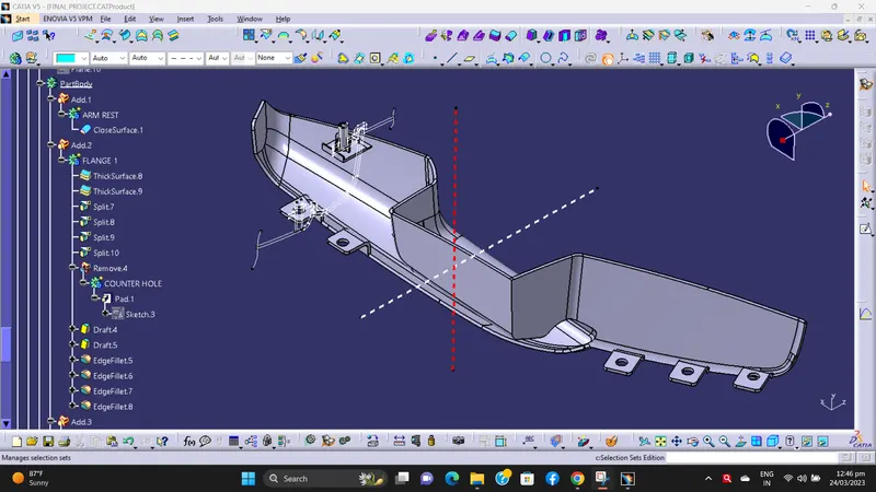
Draft analysis -
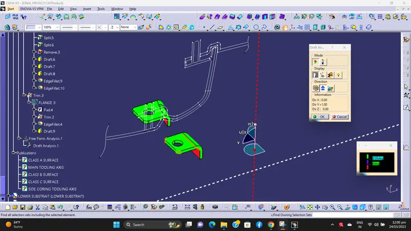
NOTE -
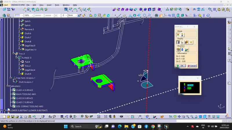
AS PER DISCUSSION WITH TECHNICAL SUPPORT MENTOR, DRAFT ANALYSIS FOR FLANGE WITH SIDE CORE TOOLING AXIS IS NOT SHOWING ACCURATLY WITH 0.45 DEG ANGLE IN MY CATIA VERSION. THATS WHY I AM PERFORMING DRAFT ANALYSIS WITH 0.35 DEG ANGLE.
KINDLY REFER THE BELOW IMAGE.
FLANGE 2 -
Sketch 1 -
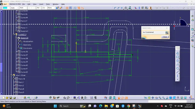
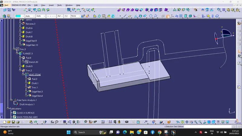
For solid body we are use pad command in part body workbench.
We are given 0.5deg draft for outer faces of flange.
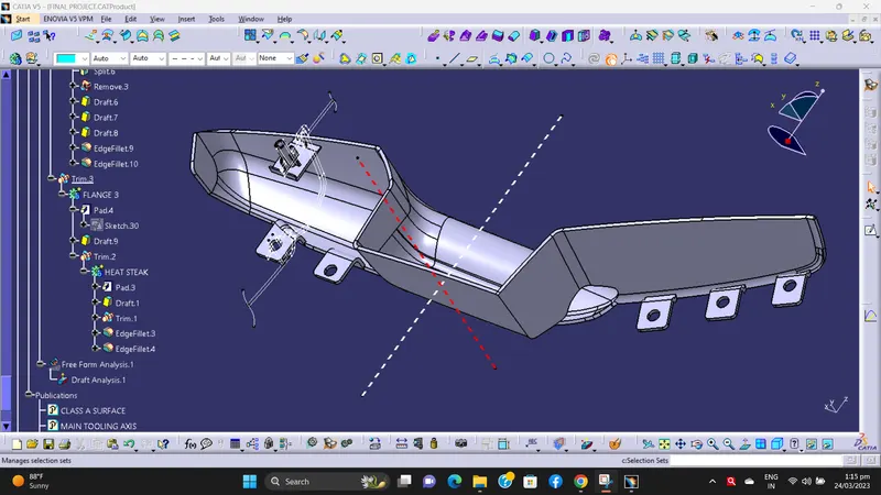
Draft analysis -
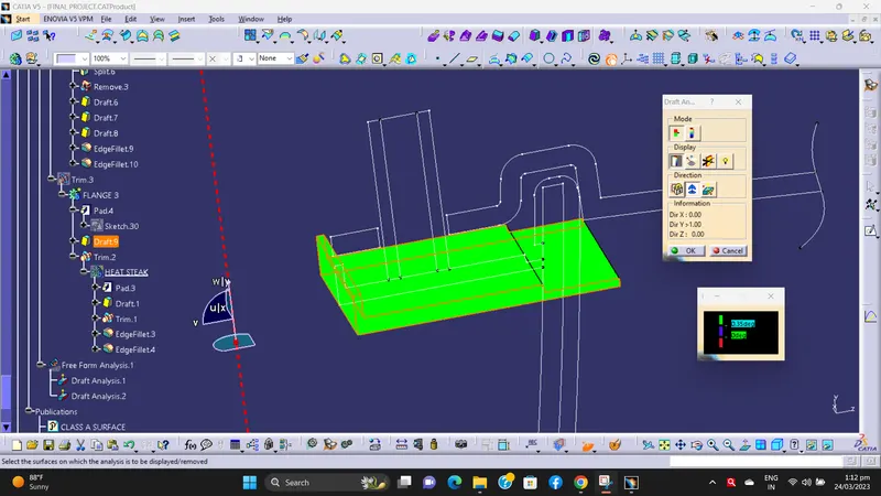
NOTE -
AS PER DISCUSSION WITH TECHNICAL SUPPORT MENTOR, DRAFT ANALYSIS FOR FLANGE WITH SIDE CORE TOOLING AXIS IS NOT SHOWING ACCURATLY WITH 0.45 DEG ANGLE IN MY CATIA VERSION. THATS WHY I AM PERFORMING DRAFT ANALYSIS WITH 0.35 DEG ANGLE.
KINDLY REFER THE BELOW IMAGE.
b) Map Pocket -
- Master sections for Map Pocket -
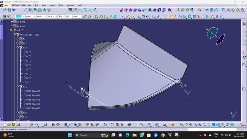
- Creation of flange -
FLANGE 1 -
Sketch 1 -
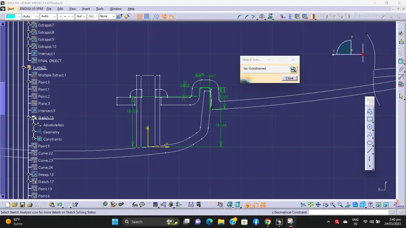
Sketch 2 -
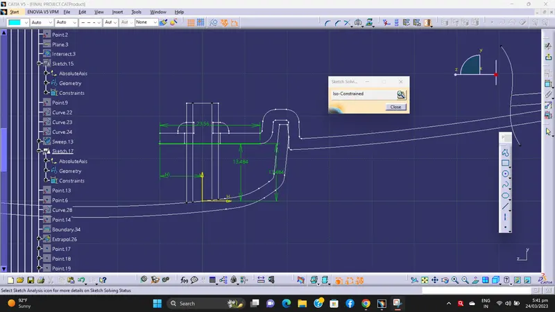
Sketch 3 -
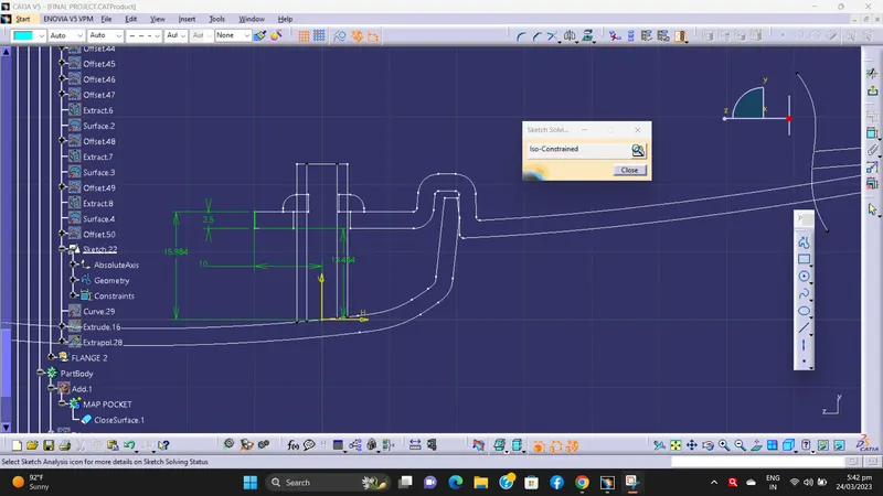
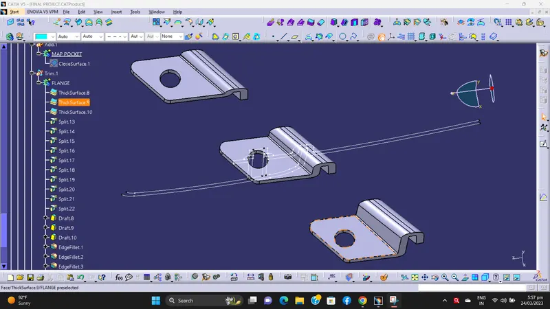
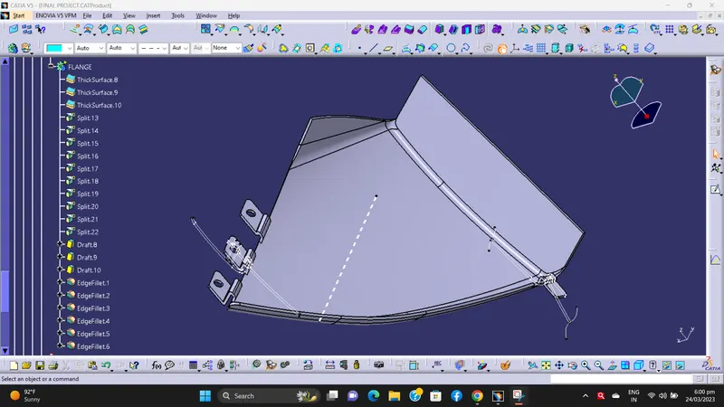
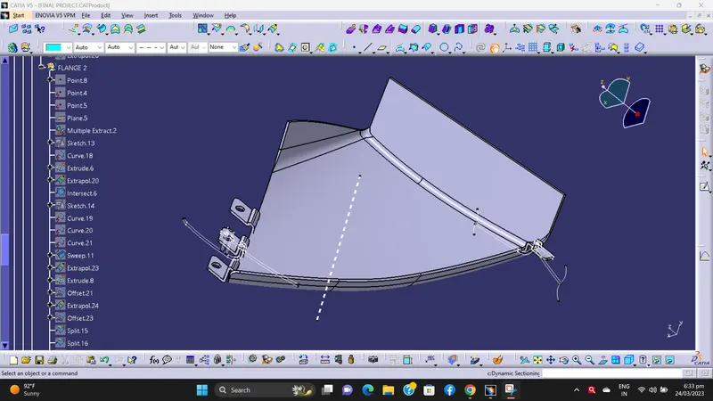
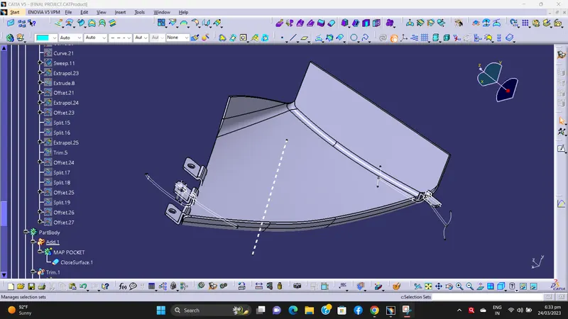
Surface oprations -
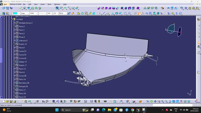
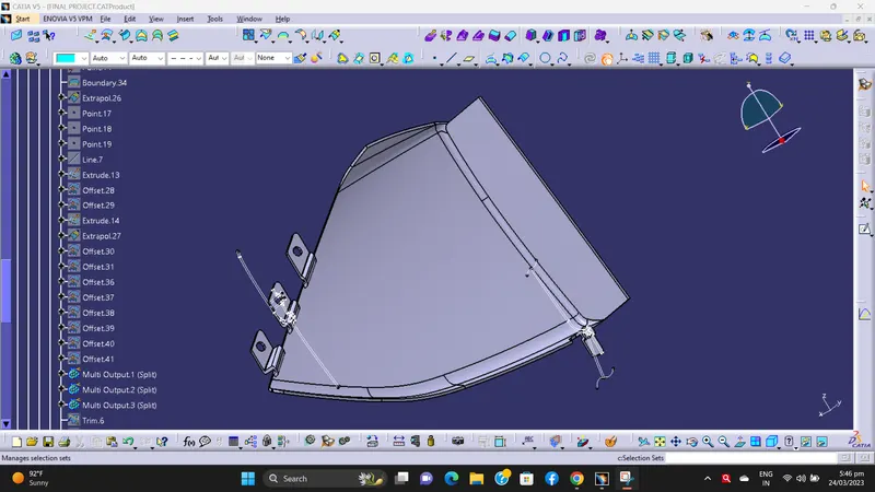
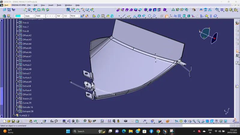
For solid body we are use thicken command in part body workbench.
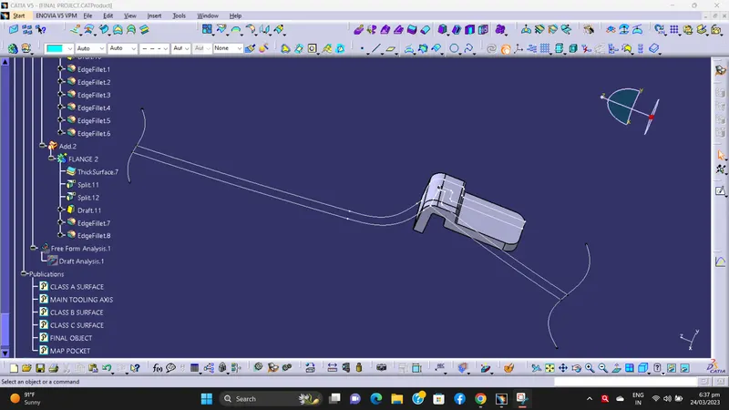
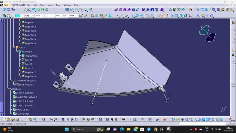
For edge fillet we are following the master section.
We are given 0.5deg draft for outer faces of flange.
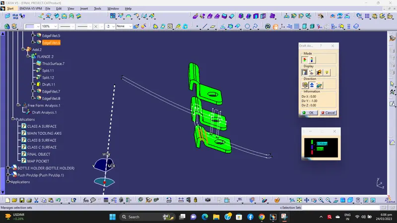
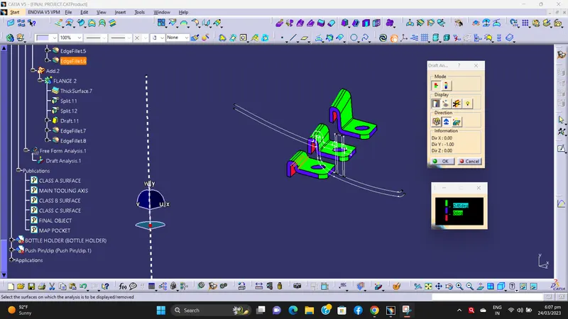
Draft Analysis -
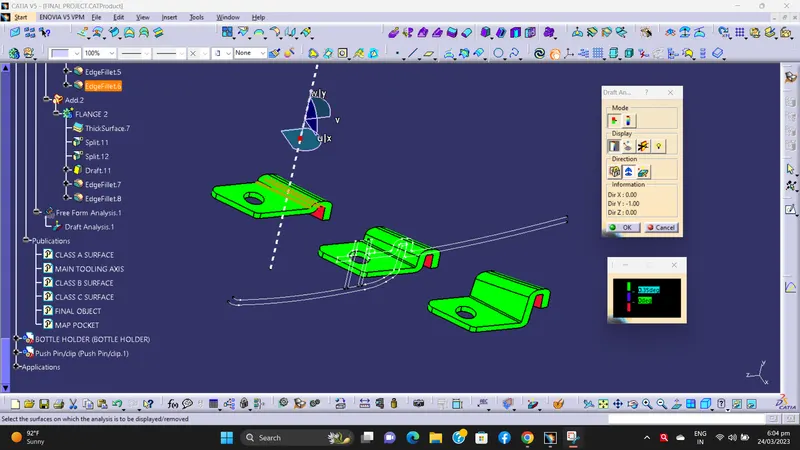
NOTE -
AS PER DISCUSSION WITH TECHNICAL SUPPORT MENTOR, DRAFT ANALYSIS FOR FLANGE WITH MAIN TOOLING AXIS IS NOT SHOWING ACCURATLY WITH 0.45 DEG ANGLE IN MY CATIA VERSION. THATS WHY I AM PERFORMING DRAFT ANALYSIS WITH 0.35 DEG ANGLE.
KINDLY REFER THE BELOW IMAGE.
FLANGE 2 -
Sketch 1 -
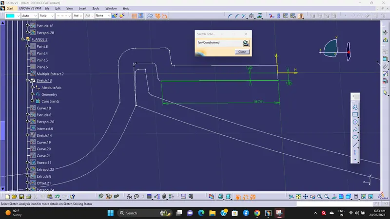
Sketch 2 -
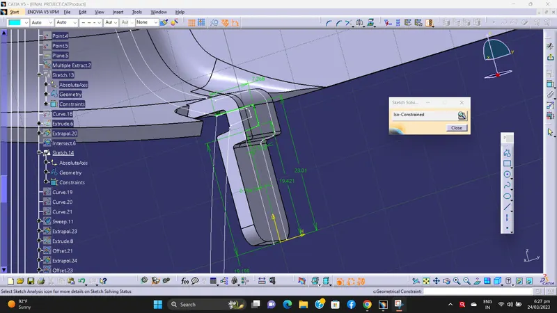
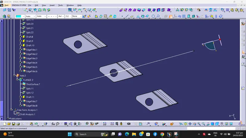
Surface oprations -
For solid body we are use thicken command in part body workbench.
For edge fillet we are following the master section.
We are given 0.5deg draft for outer faces of flange.
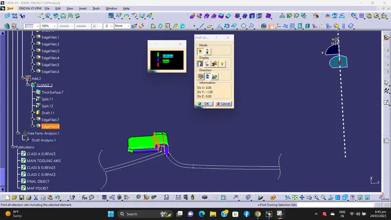
Draft Analysis -
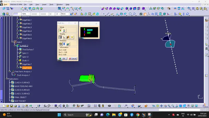
NOTE -
AS PER DISCUSSION WITH TECHNICAL SUPPORT MENTOR, DRAFT ANALYSIS FOR FLANGE WITH MAIN TOOLING AXIS IS NOT SHOWING ACCURATLY WITH 0.45 DEG ANGLE IN MY CATIA VERSION. THATS WHY I AM PERFORMING DRAFT ANALYSIS WITH 0.35 DEG ANGLE.
KINDLY REFER THE BELOW IMAGE.
B) Engineering Features (Heat Stake) -
By following master sections we create Heat Stake for Arm Rest and Lower Substrate.
a) Arm Rest -
Sketch -
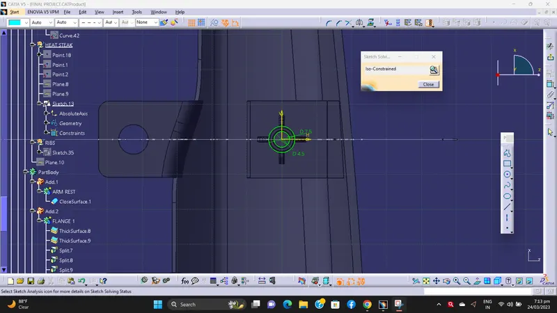
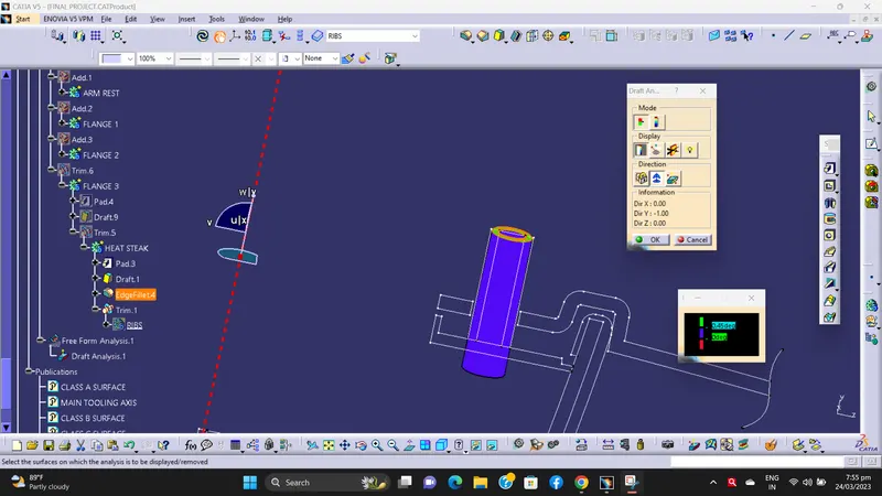
For solid body we performing pad command.
Edge fillet - 0.25mm
Providing draft angle 0.5deg inner and outer surface.
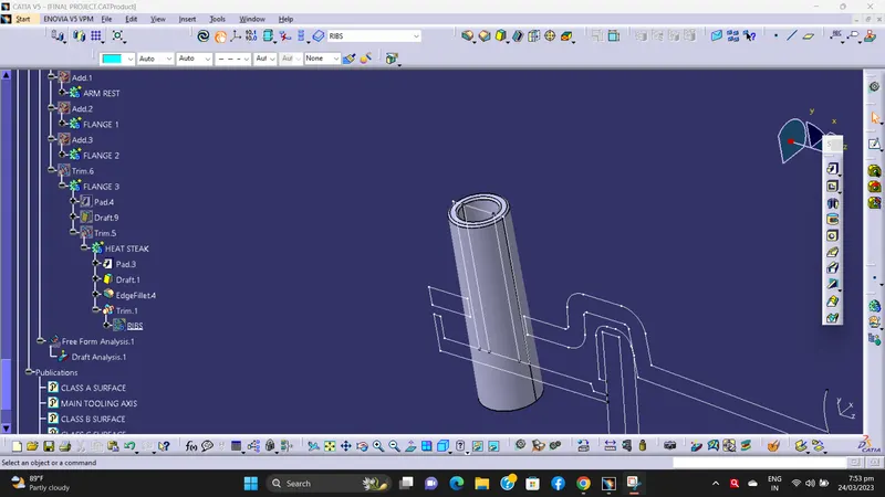
Draft Analysis -
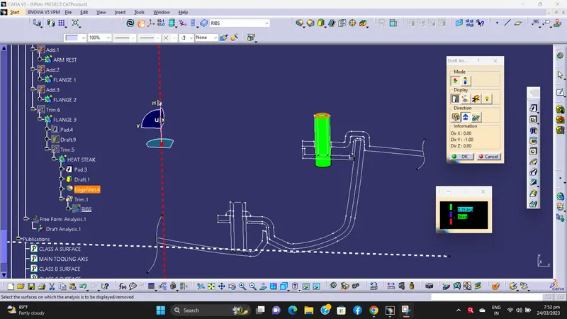
NOTE -
AS PER DISCUSSION WITH TECHNICAL SUPPORT MENTOR, DRAFT ANALYSIS FOR HEAT STAKE WITH MAIN TOOLING AXIS IS NOT SHOWING ACCURATLY WITH 0.45 DEG ANGLE IN MY CATIA VERSION. THATS WHY I AM PERFORMING DRAFT ANALYSIS WITH 0.35 DEG ANGLE.
KINDLY REFER THE BELOW IMAGE.
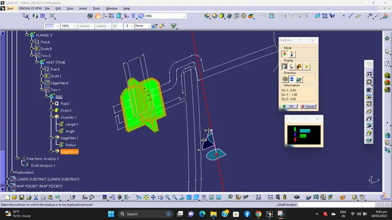
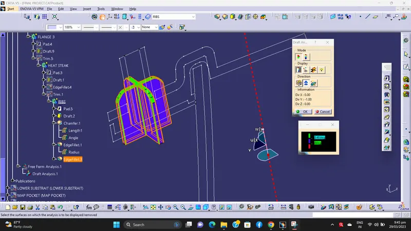
Heat Stake Rib -
Sketch -
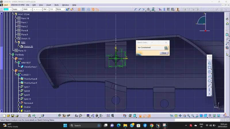
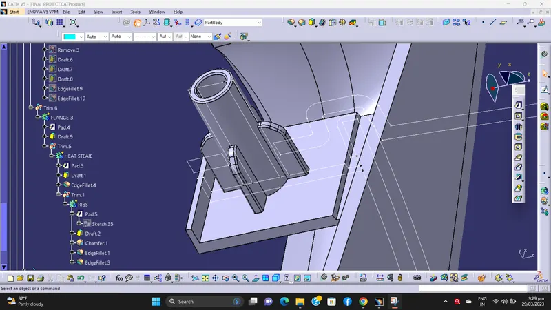
Performing the solid body operation by using PAD command in part workbemch.
Length - 11mm
Chamfer - 2mm
Edge fillet 1 - 2mm
Edge fillet 2 - 0.25mm
Draft Analysis -
NOTE -
AS PER DISCUSSION WITH TECHNICAL SUPPORT MENTOR, DRAFT ANALYSIS FOR RIB WITH MAIN TOOLING AXIS IS NOT SHOWING ACCURATLY WITH 0.45 DEG ANGLE IN MY CATIA VERSION. THATS WHY I AM PERFORMING DRAFT ANALYSIS WITH 0.35 DEG ANGLE.
KINDLY REFER THE BELOW IMAGE.
b) Lower Substrate :-
For master section 1 -
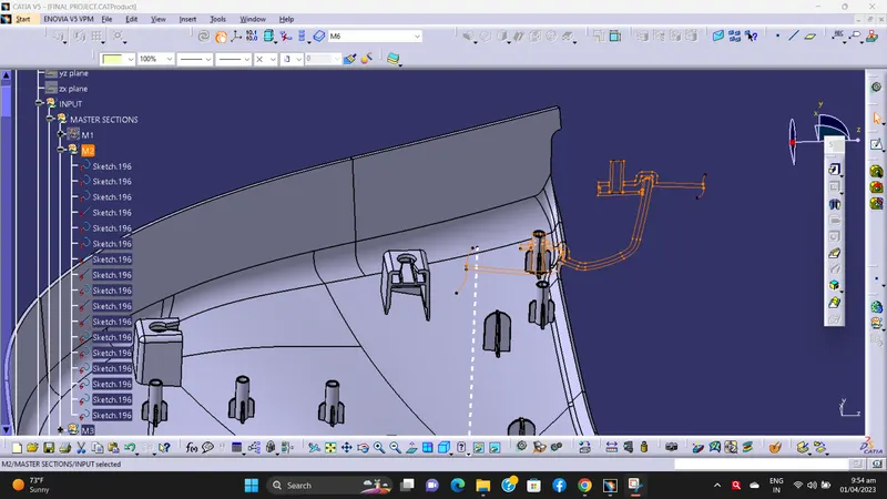
Sketch -
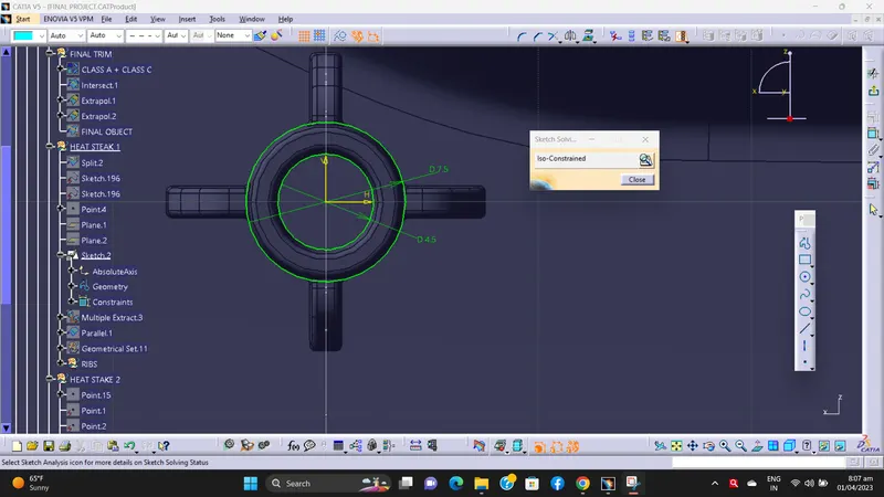
For solid body we performing pad command.
Edge fillet - 0.25mm
Providing draft angle 0.5deg inner and outer surface.
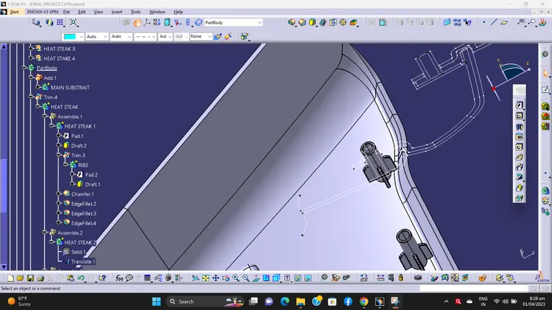
By using point repetition command we create point on lower substrate where the heate stakes are required to fix the arm rest. Then by using translation command the main heate stake is translate where the point is created.
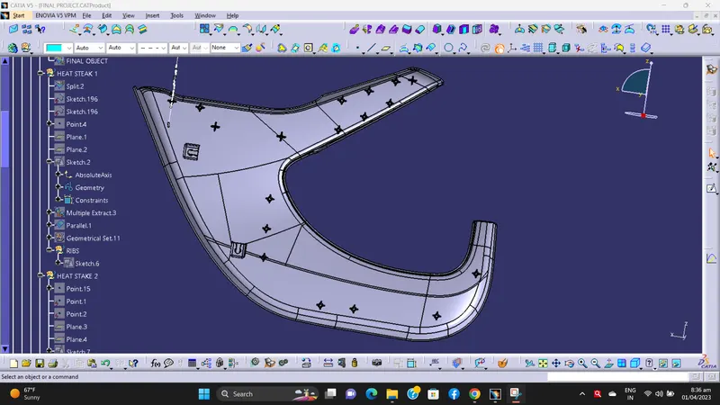
Draft Analysis -
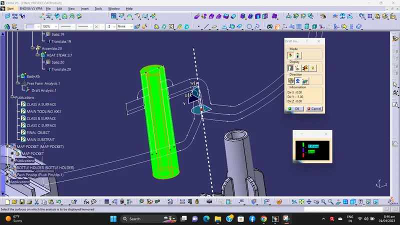
NOTE -
AS PER DISCUSSION WITH TECHNICAL SUPPORT MENTOR, DRAFT ANALYSIS FOR HEAT STAKE WITH MAIN TOOLING AXIS IS NOT SHOWING ACCURATLY WITH 0.45 DEG ANGLE IN MY CATIA VERSION. THATS WHY I AM PERFORMING DRAFT ANALYSIS WITH 0.35 DEG ANGLE.
KINDLY REFER THE BELOW IMAGE.
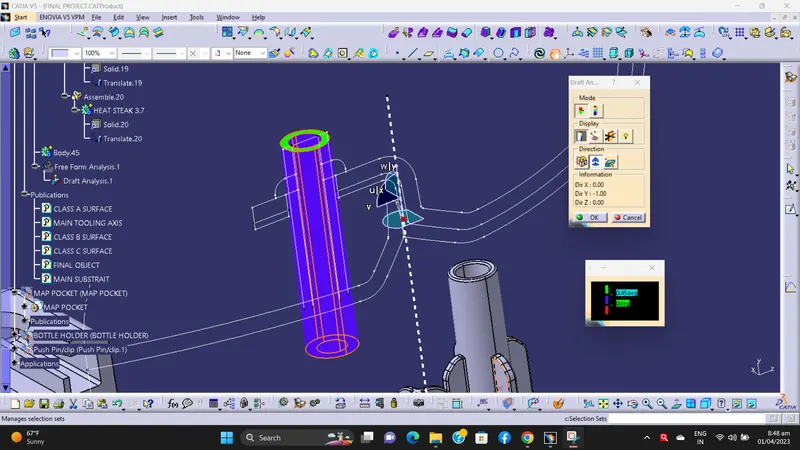
Heat Stake Rib -
Sketch -
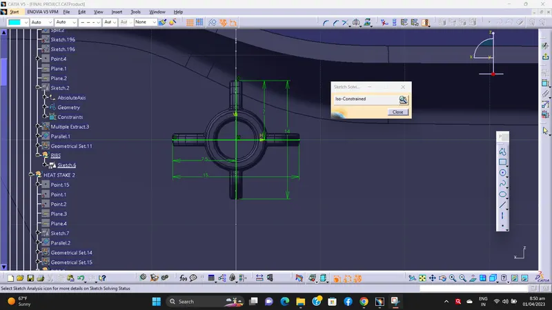
Performing the solid body operation by using PAD command in part workbemch.
Length - 14.023mm
Chamfer - 2mm
Edge fillet 1 - 2mm
Edge fillet 2 - 0.25mm
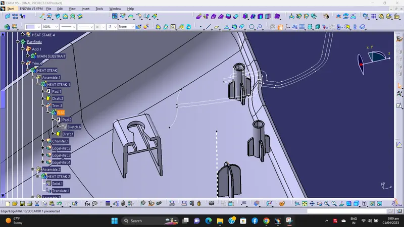
Draft Analysis -
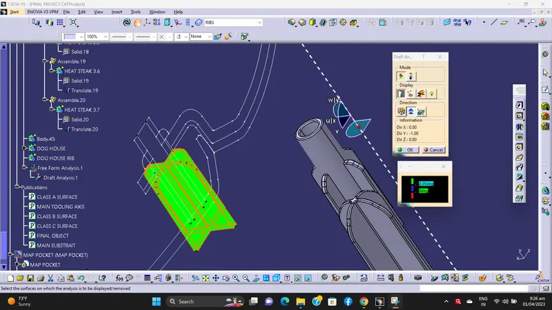
NOTE -
AS PER DISCUSSION WITH TECHNICAL SUPPORT MENTOR, DRAFT ANALYSIS FOR RIB WITH MAIN TOOLING AXIS IS NOT SHOWING ACCURATLY WITH 0.45 DEG ANGLE IN MY CATIA VERSION. THATS WHY I AM PERFORMING DRAFT ANALYSIS WITH 0.35 DEG ANGLE.
KINDLY REFER THE BELOW IMAGE.
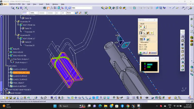
For master section 2 -
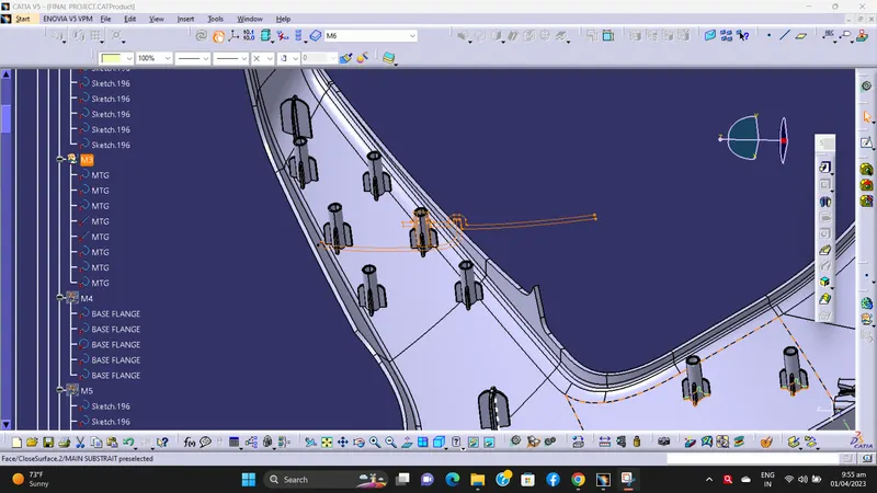
Sketch -
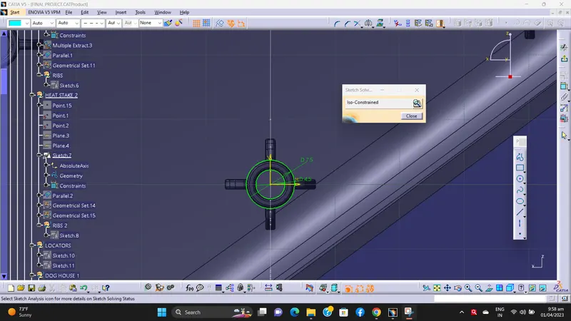
For solid body we performing pad command.
Edge fillet - 0.25mm
Providing draft angle 0.5deg inner and outer surface.
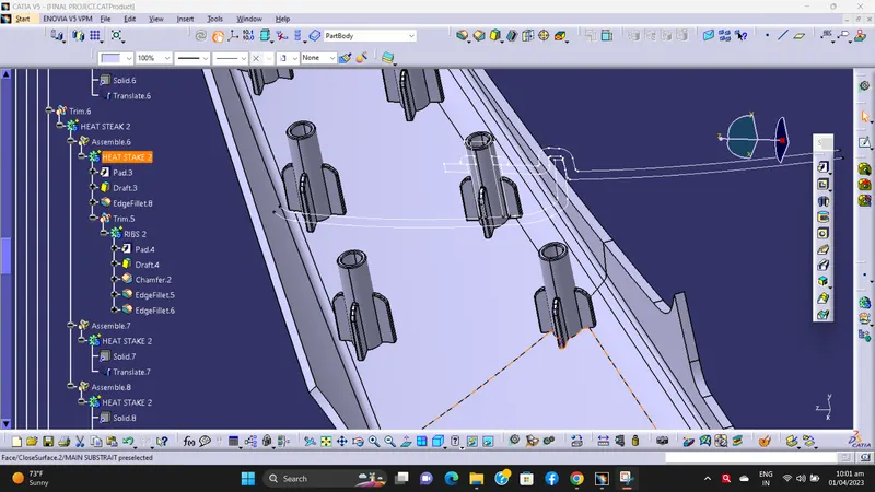
By using point repetition command we create point on lower substrate where the heate stakes are required to fix the map pocket. Then by using translation command the main heate stake is translate where the point is created.
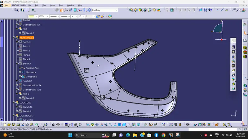
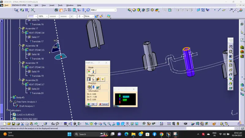
Draft Analysis -
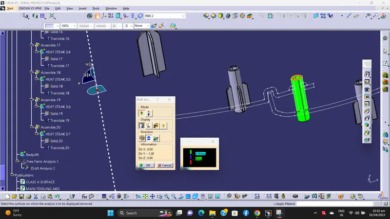
NOTE -
AS PER DISCUSSION WITH TECHNICAL SUPPORT MENTOR, DRAFT ANALYSIS FOR HEAT STAKE WITH MAIN TOOLING AXIS IS NOT SHOWING ACCURATLY WITH 0.45 DEG ANGLE IN MY CATIA VERSION. THATS WHY I AM PERFORMING DRAFT ANALYSIS WITH 0.35 DEG ANGLE.
KINDLY REFER THE BELOW IMAGE.
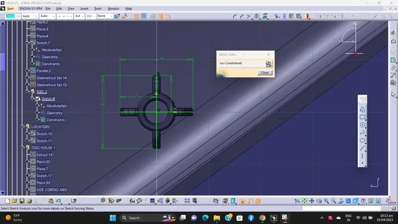
Heat Stake Rib -
Sketch -
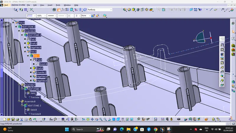
Performing the solid body operation by using PAD command in part workbench.
Length - 12mm
Chamfer - 2mm
Edge fillet 1 - 2mm
Edge fillet 2 - 0.25mm
Draft angle - 0.5deg
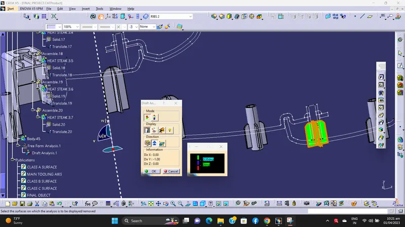
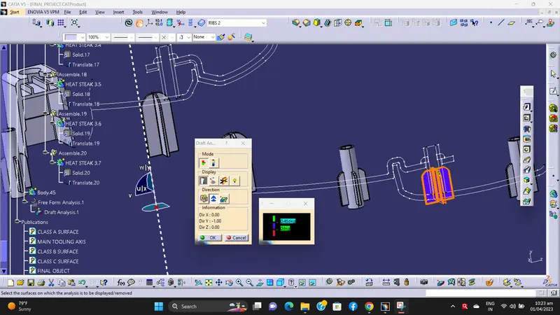
Draft Analysis -
NOTE -
AS PER DISCUSSION WITH TECHNICAL SUPPORT MENTOR, DRAFT ANALYSIS FOR RIB WITH MAIN TOOLING AXIS IS NOT SHOWING ACCURATLY WITH 0.45 DEG ANGLE IN MY CATIA VERSION. THATS WHY I AM PERFORMING DRAFT ANALYSIS WITH 0.35 DEG ANGLE.
KINDLY REFER THE BELOW IMAGE.
9) Creation of additional engineering features (Dog house & locators) -
We are creating dog house and locators on Lower Substrate.
a) Dog house -
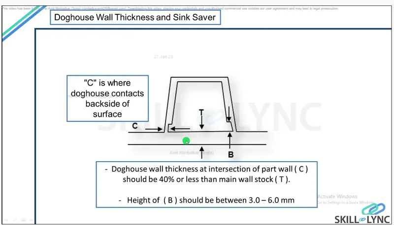
We are design the dog house by following all design standards.
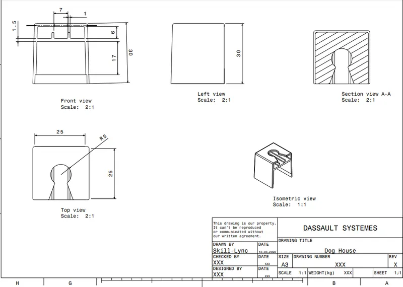
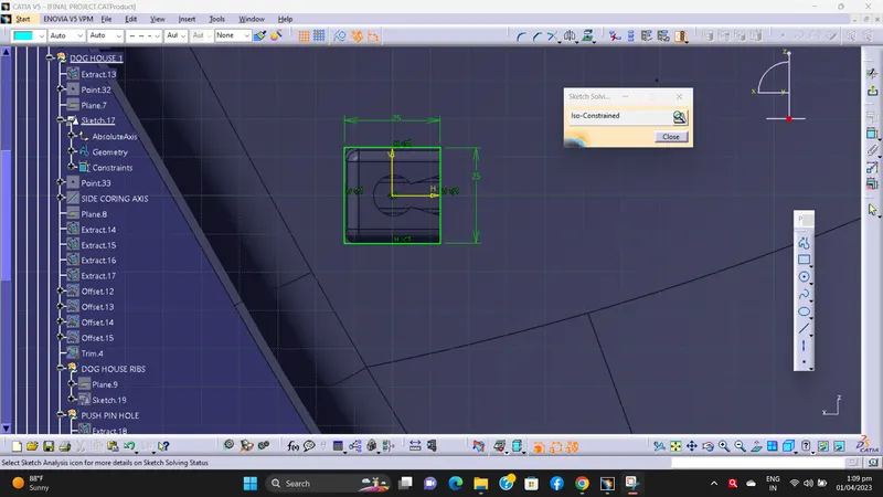
Sketch 1 - Dog House.
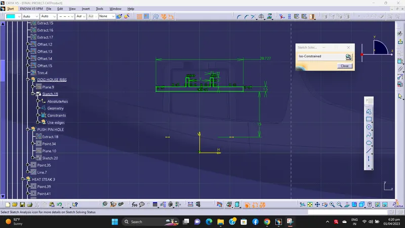
Sketch 2 - Dog House Rib.
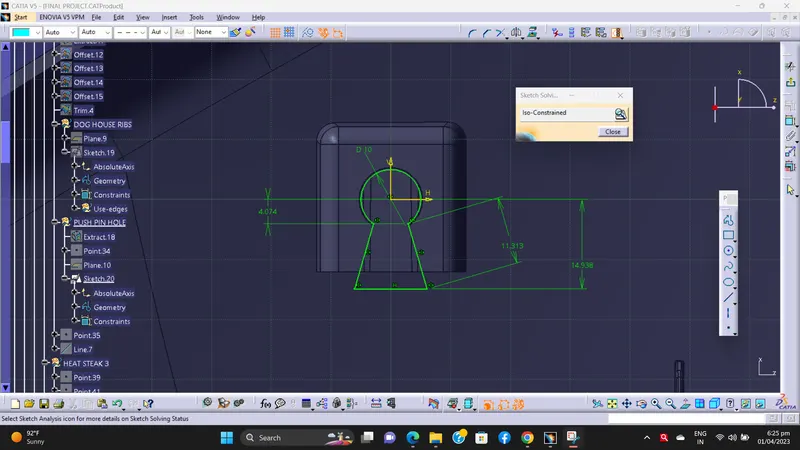
Sketch 3 - Push Pin Hole.
Surface Oprations -
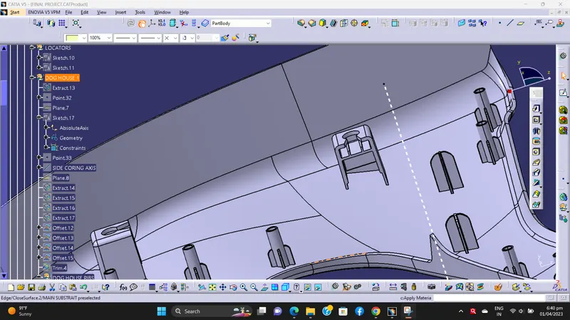
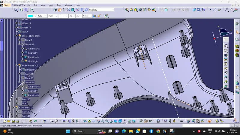
Performing the solid body operation by using PAD command in part workbench.
Draft angle for outer face - 1.5deg.
Draft angle for outer face - 0.5deg.
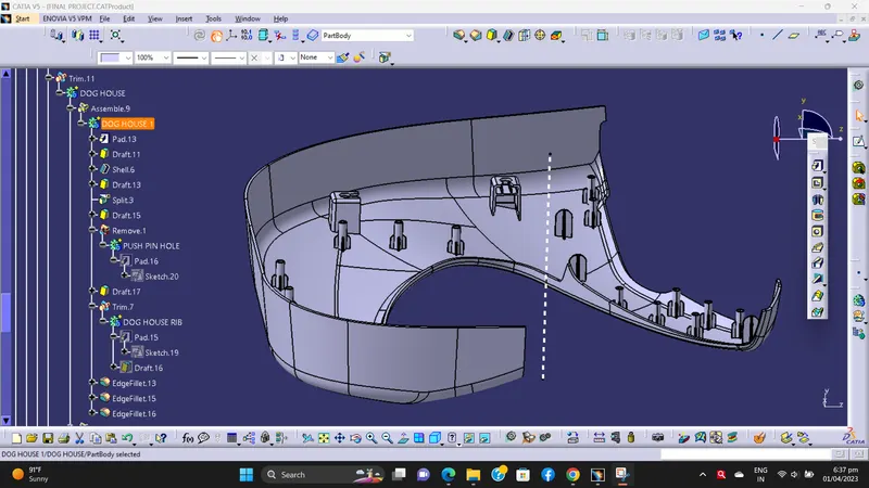
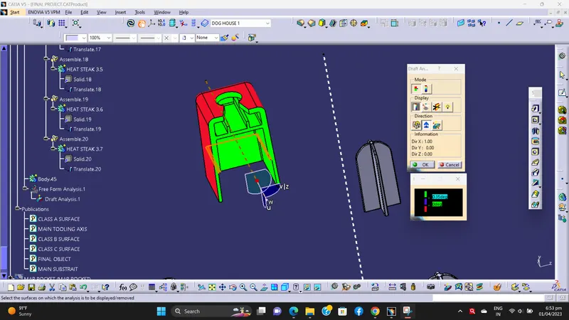
Draft analysis for dog house with main tooling axis -
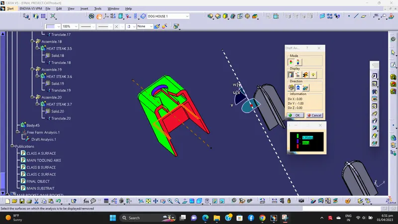
NOTE -
AS PER DISCUSSION WITH TECHNICAL SUPPORT MENTOR, DRAFT ANALYSIS FOR DOG HOUSE WITH MAIN TOOLING AXIS IS NOT SHOWING ACCURATLY WITH 1.45 DEG ANGLE IN MY CATIA VERSION. THATS WHY I AM PERFORMING DRAFT ANALYSIS WITH 1.35 DEG ANGLE.
KINDLY REFER THE BELOW IMAGE.
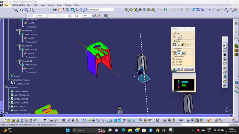
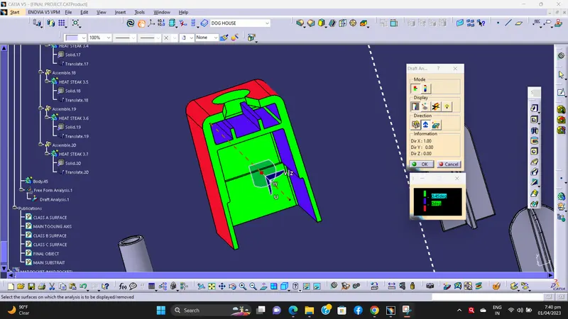
Draft analysis for dog house with side core tooling axis -
NOTE -
AS PER DISCUSSION WITH TECHNICAL SUPPORT MENTOR, DRAFT ANALYSIS FOR DOG HOUSE WITH MAIN TOOLING AXIS IS NOT SHOWING ACCURATLY WITH 0.45 DEG ANGLE IN MY CATIA VERSION. THATS WHY I AM PERFORMING DRAFT ANALYSIS WITH 0.35 DEG ANGLE.
KINDLY REFER THE BELOW IMAGE.
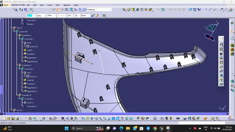
b) Locators -
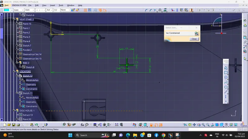
Sketch 1 -
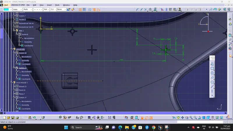
Sketch 2 -
Performing the solid body operation by using PAD command in part workbench.
Thickness - 1.5mm.
Height - 23mm.
Chamfer - 4mm.
Edge fillet 1 - 4mm.
Edge fillet 2 - 0.25mm.
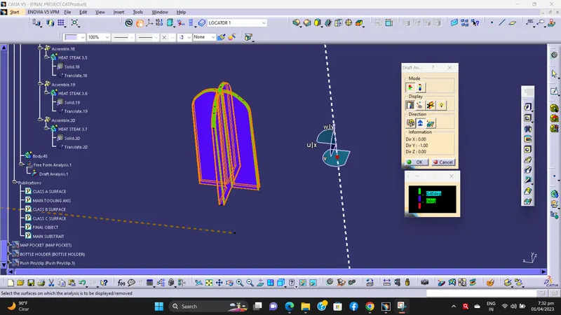
Draft angle - 0.5deg.
Draft analysis -
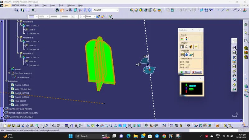
NOTE -
AS PER DISCUSSION WITH TECHNICAL SUPPORT MENTOR, DRAFT ANALYSIS FOR LOCATORS WITH MAIN TOOLING AXIS IS NOT SHOWING ACCURATLY WITH 0.45 DEG ANGLE IN MY CATIA VERSION. THATS WHY I AM PERFORMING DRAFT ANALYSIS WITH 0.35 DEG ANGLE.
KINDLY REFER THE BELOW IMAGE.
c) Flages for Bottel Holder -
Sketch 1 for Flange 1 -
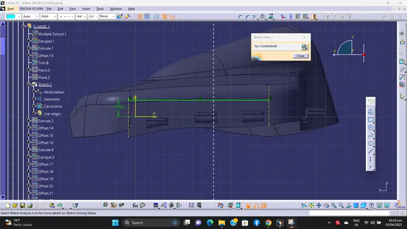
Sketch 2 for Flange 2 -
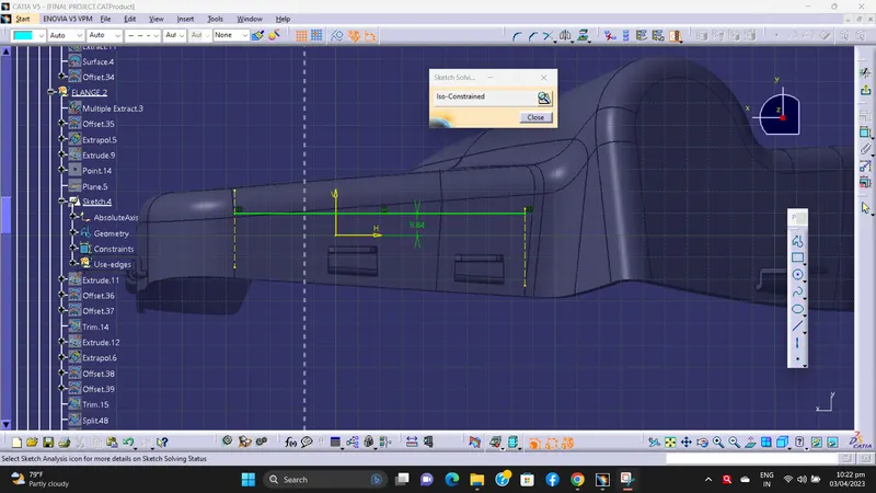
Sketch 3 for Flange 3 -
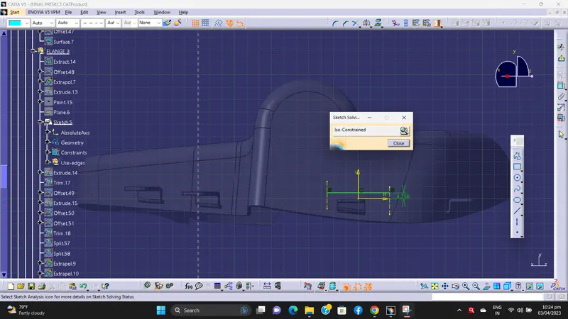
Sketch 4 for Flange 4 -
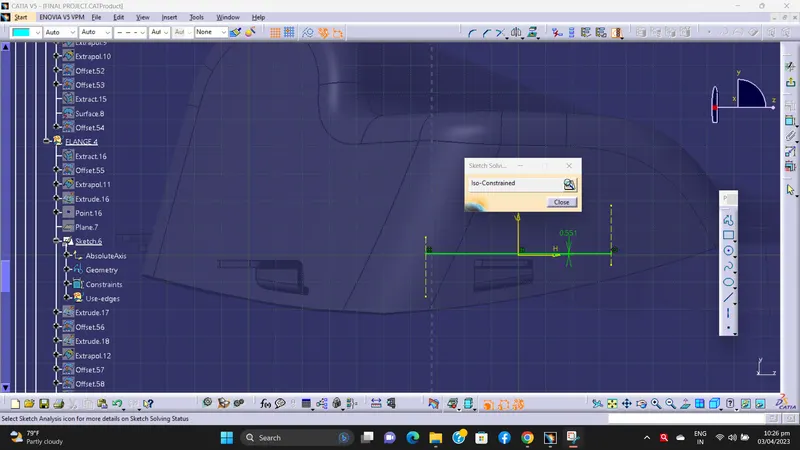
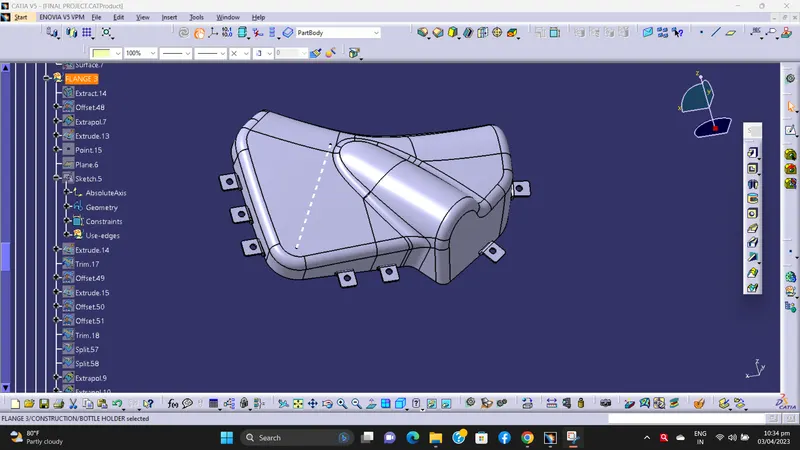
Surfacing oprations used for all four Flanges -
Flange 1 -
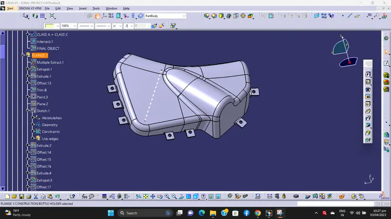
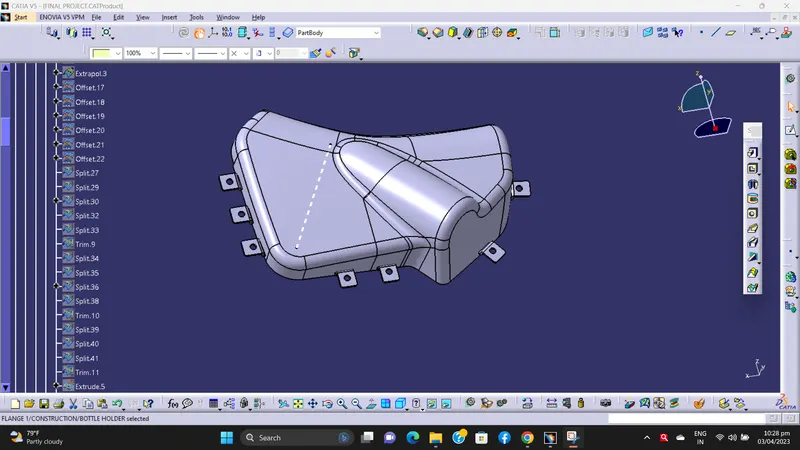
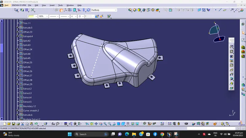
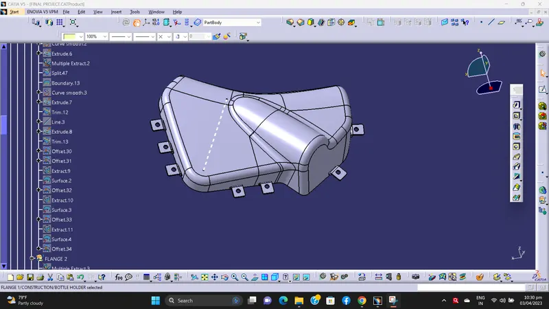
Flange 2 -
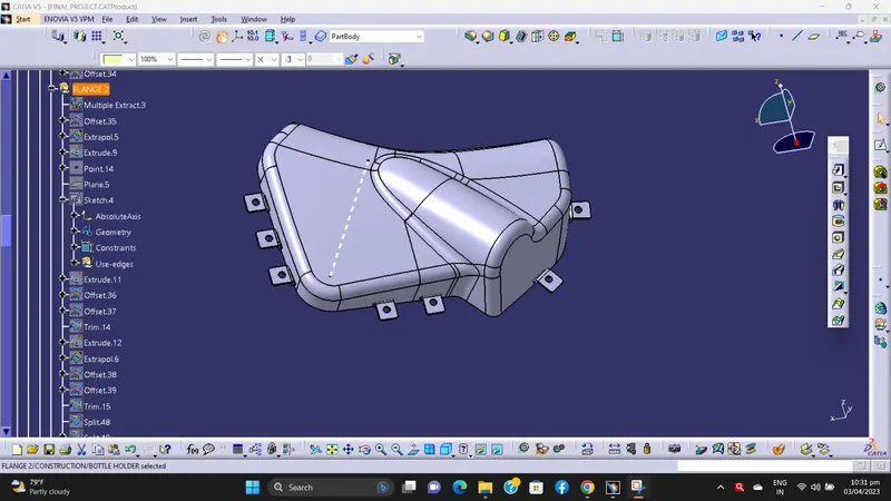
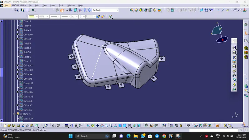
Flange 3 -
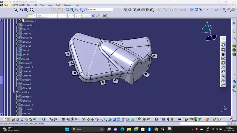
Flange 4 -
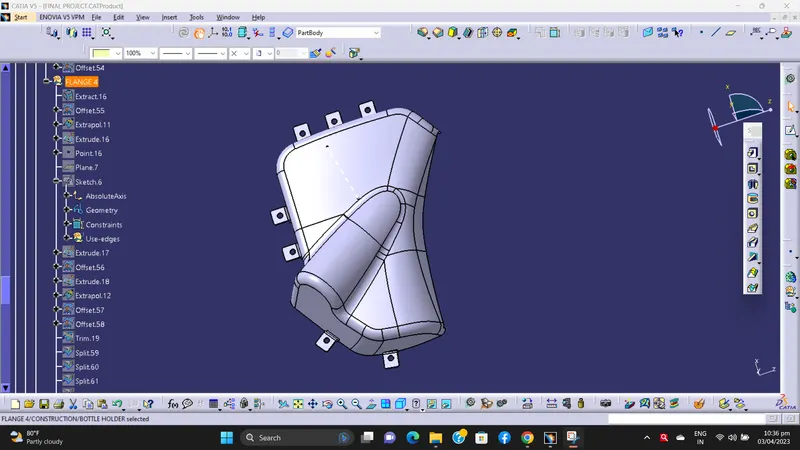
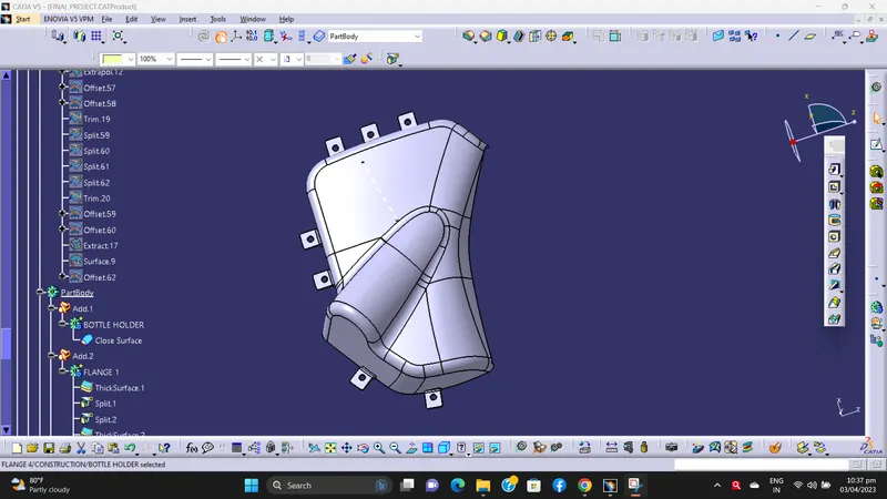
For solid body for all four Flanges we are use Thicken Command in part workbench -
Thick size - 2.5mm
Outer edge fillet - 3mm
Inner edge fillet - 0.5mm
Draft angel - 0.5deg.
Flange 1 -
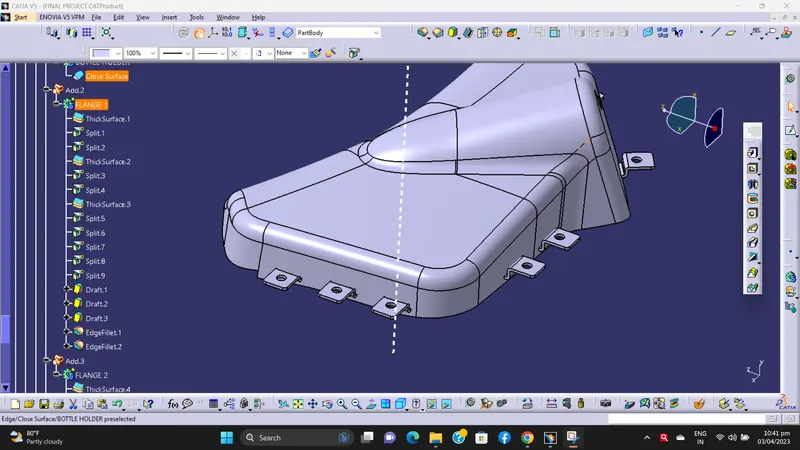
Flange 2 -
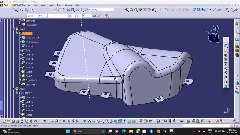
Flange 3 -
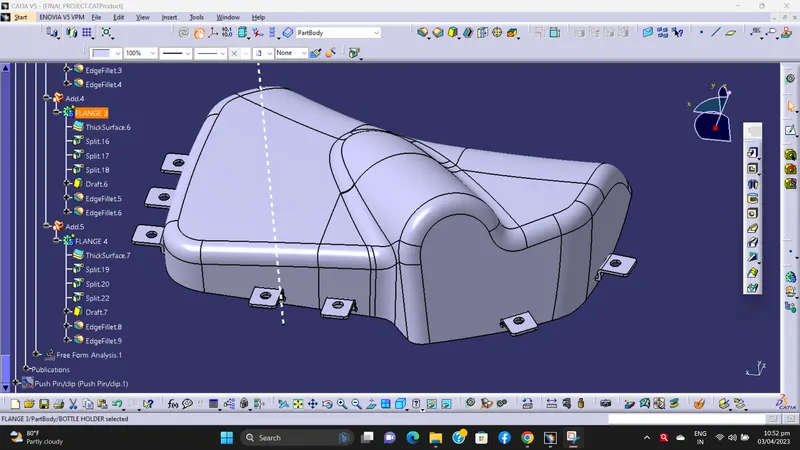
Flange 4 -
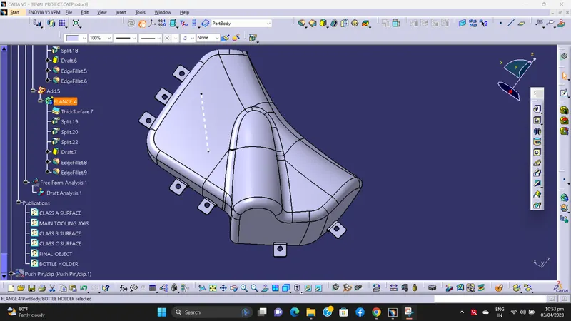
Draft analysis -
Flange 1 -
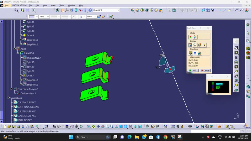
Flange 2 -
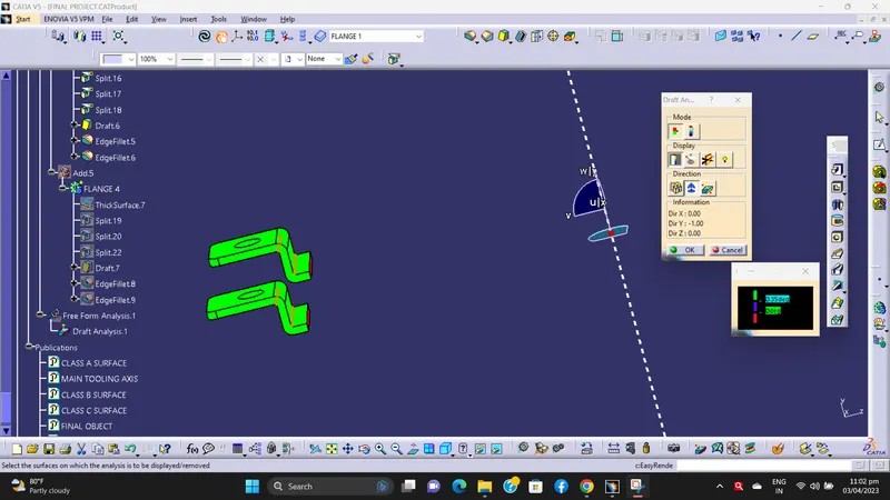
Flange 3 -
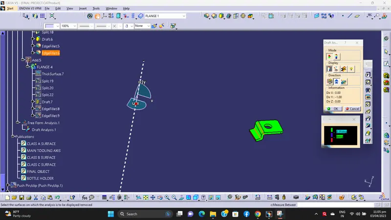
Flange 4 -
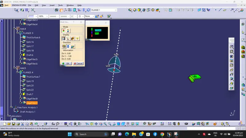
NOTE -
AS PER DISCUSSION WITH TECHNICAL SUPPORT MENTOR, DRAFT ANALYSIS FOR FLANGES WITH MAIN TOOLING AXIS IS NOT SHOWING ACCURATLY WITH 0.45 DEG ANGLE IN MY CATIA VERSION. THATS WHY I AM PERFORMING DRAFT ANALYSIS WITH 0.35 DEG ANGLE.
10) Assemble push pin with dog house -
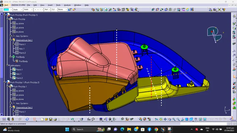
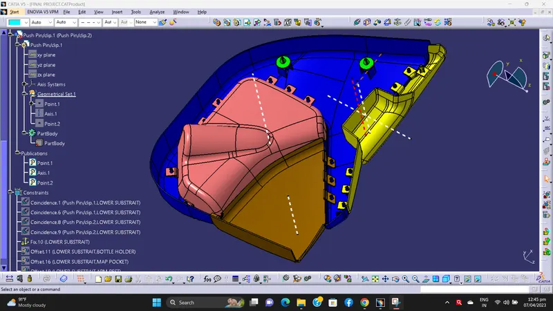
For the assembly of push pin with dog house, we use assembly workbench. In that we fix the lower substrate by using fix constrain. Then by using coinsidence constrain for dog house and push pin, boath are get assembled.
We are use two push pin for two dog house.
Constrains thats we are use -
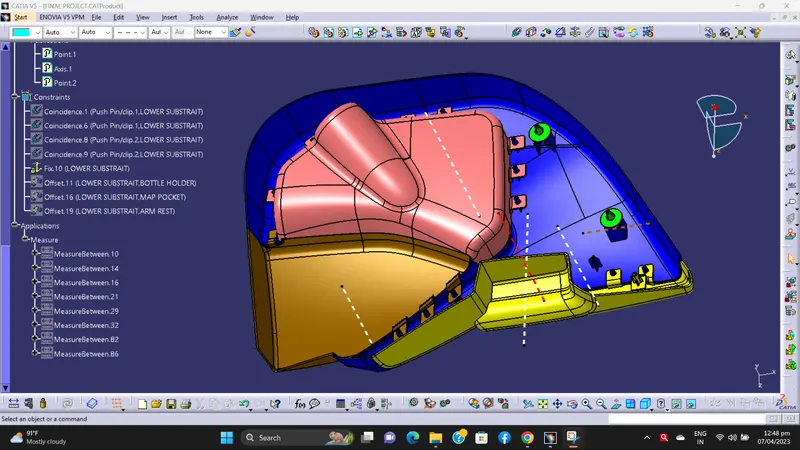
Some other images -
1) Isometric view -
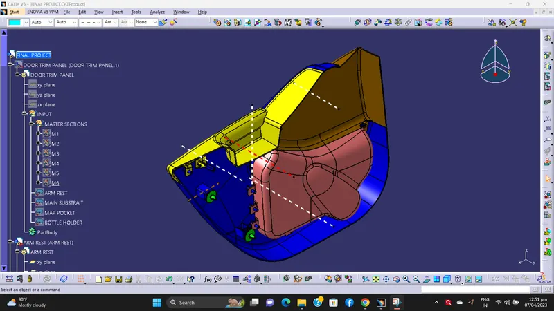
2) Front view -
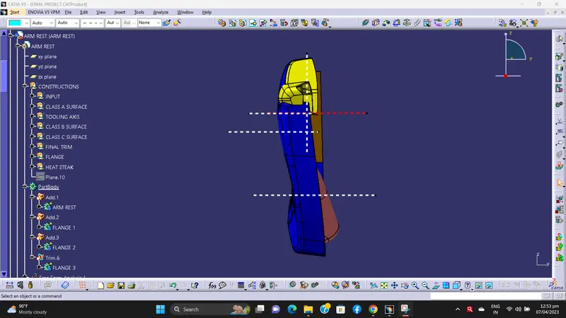
3) Back view -
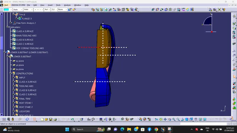
4) Left view -
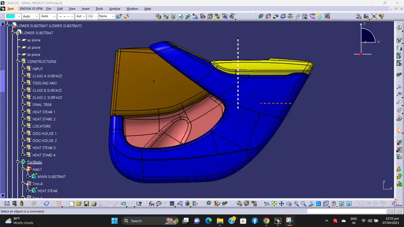
5) Right view -
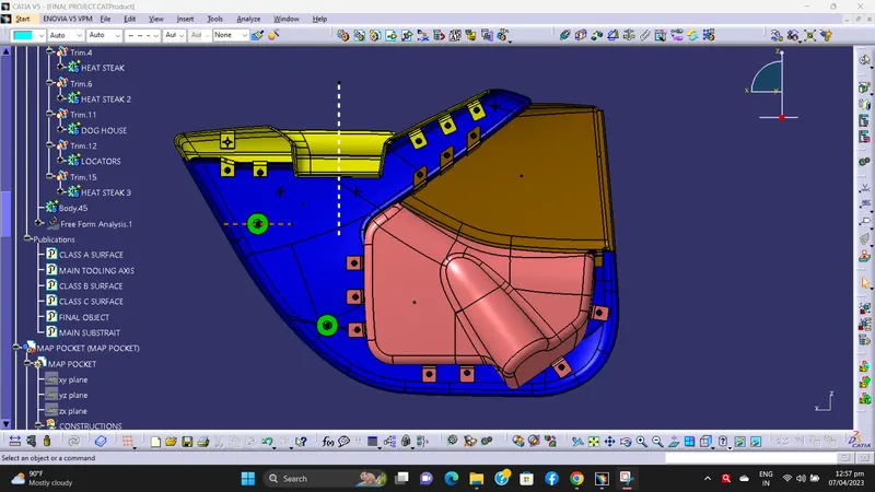
6) Top View -
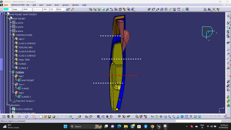
7) Bottom View -