Week 12- Final project
AIM
To create a CAD model for development of a Door Trim panel following inputs as like in OEM and tier1 companies.
OBJECTIVES
- Find an attachment strategy for the door panel complete work.
- Use Push pin with Dog house for Lower substrate – Door panel attachment
- Use heat stakes for part to part attachment.
- Perform draft analysis on the solid part model with all engineering features
REPORT
1. Arranging the assembly file
- First we open a new product file.
- We import the given part file into the assembly.
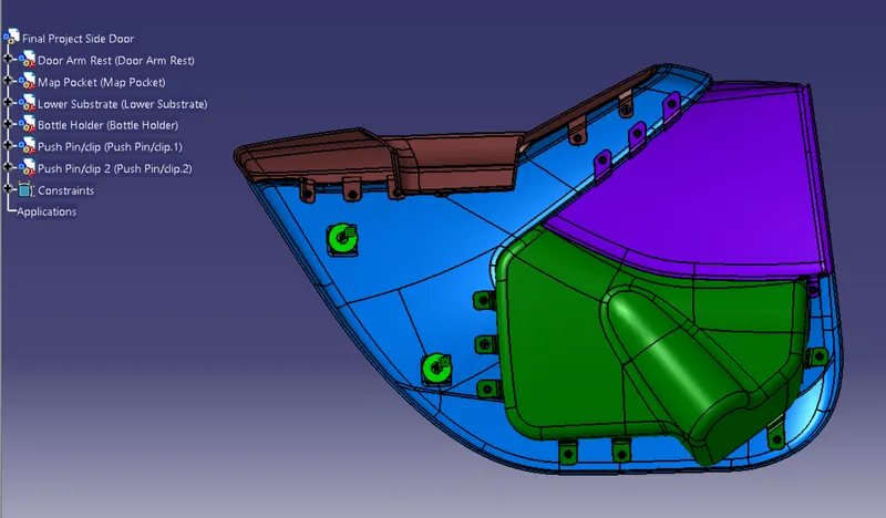
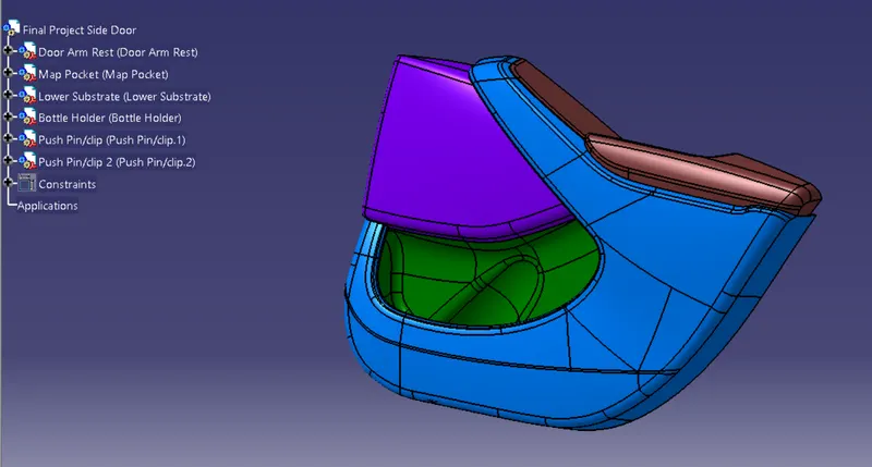
- We import the file four times. Then we seperate the parts by hiding the unneccessary elements as shown below and name them appropiately.
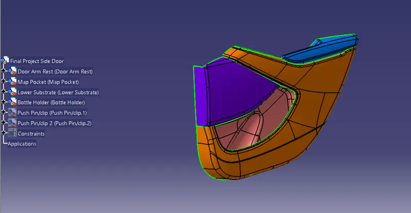
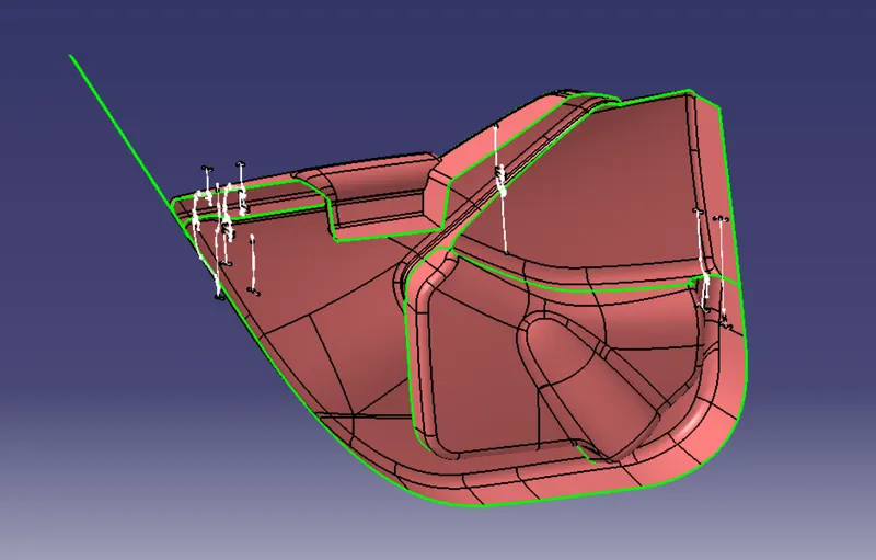
- The above picture represents the class A surface.
- After that save the files into a single folder using save management option.
2. Creation of tooling axis and draft analysis on class A
After arranging the assembly file, we create the tooling axis for each part
1. Tooling Axis and Draft analysis for Door rest arm
- First we check if the given class A surface needs any improvement.
- Once all the improvements are done, we create the tooling axis.
- Here we create the tooling axis by using bisecting line method.
- We take intersection of the side walls, then draw two lines on the side walls.
- We then form a new line bisecting those two lines forming our tooling axis.
- But due to the shape of the surface being complex, we cannot clear the surface using a single tooling axis.
- So we also create another axis called as side core tooling axis to clear the other regions
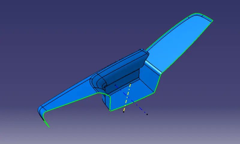
- Below figure the yellow line represents the tooling axis and the blue one represents the side core axis.
- Now we perform the draft analysis on class A surface to show the effectiveness of tooling axis.
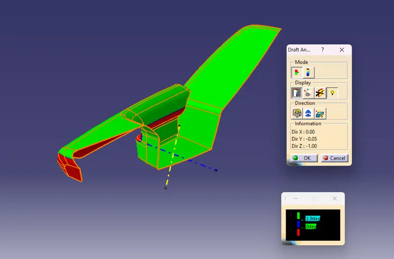
- To do that we click on the draft analysis icon, and then place the compass on the appropriate tooling axis and click on the surface to see the results.
- Given below represents the results of using the main tooling axis;
- The region which are not being cleared are cleared using the side core tooling axis,
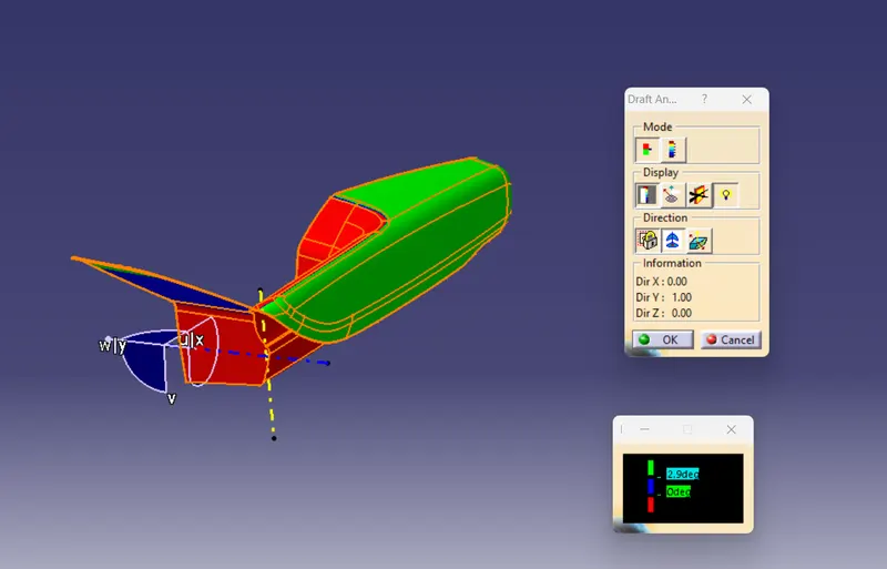
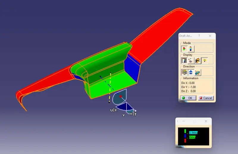
- Here to clear the surface the tool comes form both the side of the side core axis.
- Given below represents the draft analysis of class A by side core axis from one side
- The other region is also cleared by the side core axis as shown below;
2. Tooling Axis and Draft analysis for Map Pocket
- Here to create a tooling axis, we create a point on the center of the surface and draw a line towards the y direction to form our tooling axis.
- Given below is the tooling axis for Map pocket. Similarly we create a side core axis too for this Surface. The yellow line represents the tooling axis and the blue ine represents the side core axis.
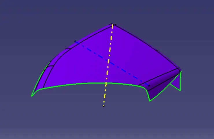
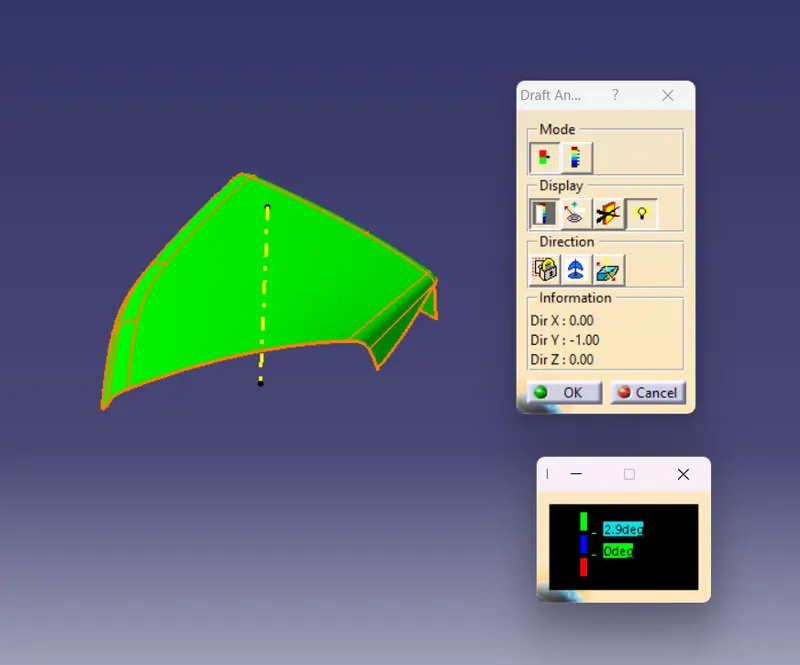
- We then run the draft analysis on class A surface as we done for arm rest. But here the class A clears fully on a single tooling axis.
- The draft analysis is given below;
3. Tooling Axis and Draft analysis for Lower substrate
- Firstly we improve the class A surface.
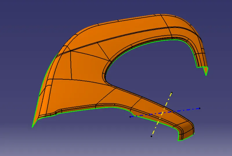
- Then using the point - direction method we create the tooling axis.
- Similarly we create the side core axis too
- Given below is the tooling axis in yellow and side core axis in blue.
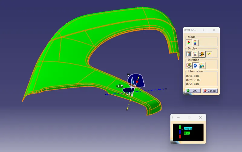
- Similarly we do draft analysis on the class A and the results are given below;
4. Tooling Axis and Draft analysis for Bottle holder
- Using the point - direction method we create the tooling axis.
- Similarly we create the side core axis too
- Given below is the tooling axis in yellow and side core axis in blue.
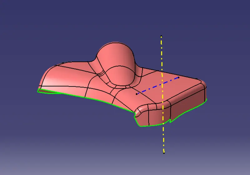
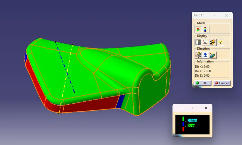
- Similarly we do draft analysis on the class A and the results are given below. From below draft analysis we see that the bottle holder Class A is not manufacturable because at some regions it is showing negative draft and this would be notified to the styling team.
3. Creation of B Surface
1. Creation of B surface for Door arm rest
- To create class B surface we calculate the thickness using the master section.
- It was found out to be 2.5mm.
- So we offset the class A surface 2.5mm inside to form the B surface
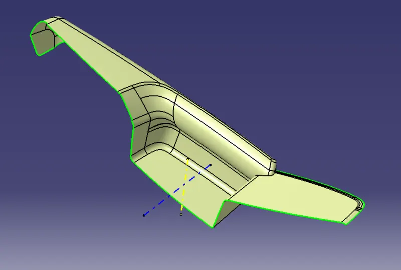
- Any surface irregularities observed will be fixed to form the class B surface as shown below:
2. Creation of B surface for Map Pocket
- Similarly we calculate the thickness from master section.
- It was found out to be 2.5mm.
- So we offset the class A surface 2.5mm inside to form the B surface
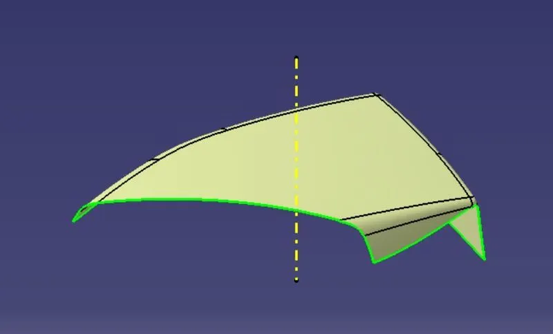
- Any surface irregularities observed will be fixed using spline , multi section etc to form the class B surface as shown below:
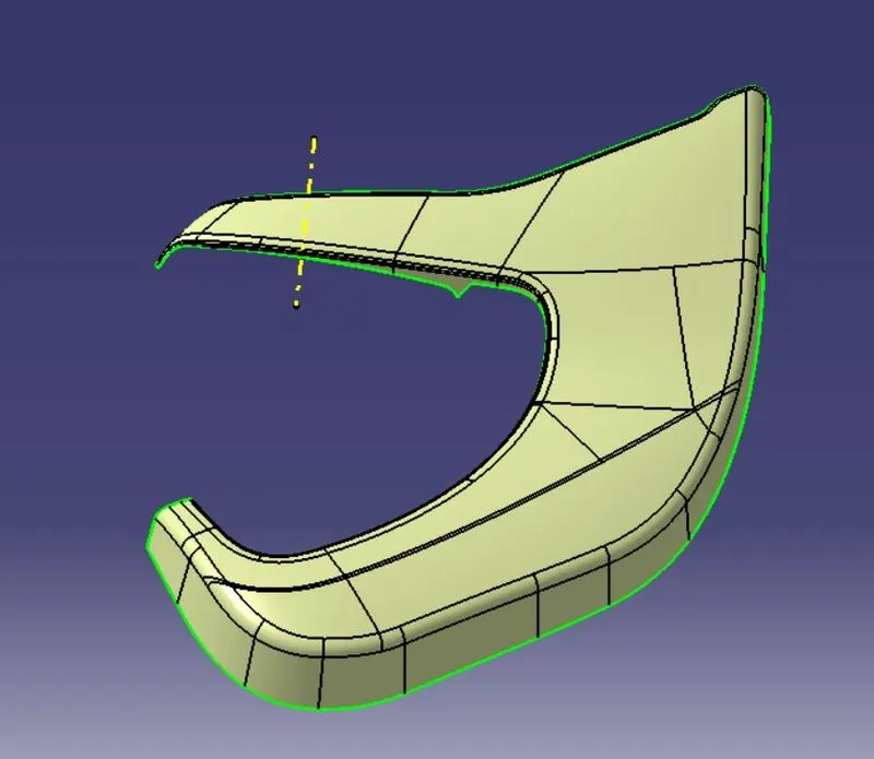
3. Creation of B surface for Lower substrate
- Here too the thickness was found to be 2.5
- We offset the class A to form the B surface.
- Here the B surface turned out fine and hence no improvements was required.
- The B surface is shown below;
4. Creation of B surface for Bottle holder
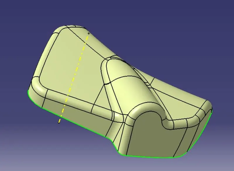
- Here we assume the thickness to be 2.5 since no master section is given for this region.
- We offset the class A to form the B surface.
- Here the B surface turned out fine and hence no improvements was required.
- The B surface is shown below;
4. Creation of C Surface
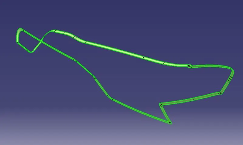
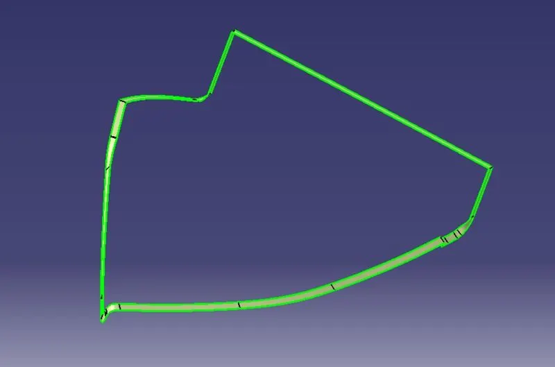
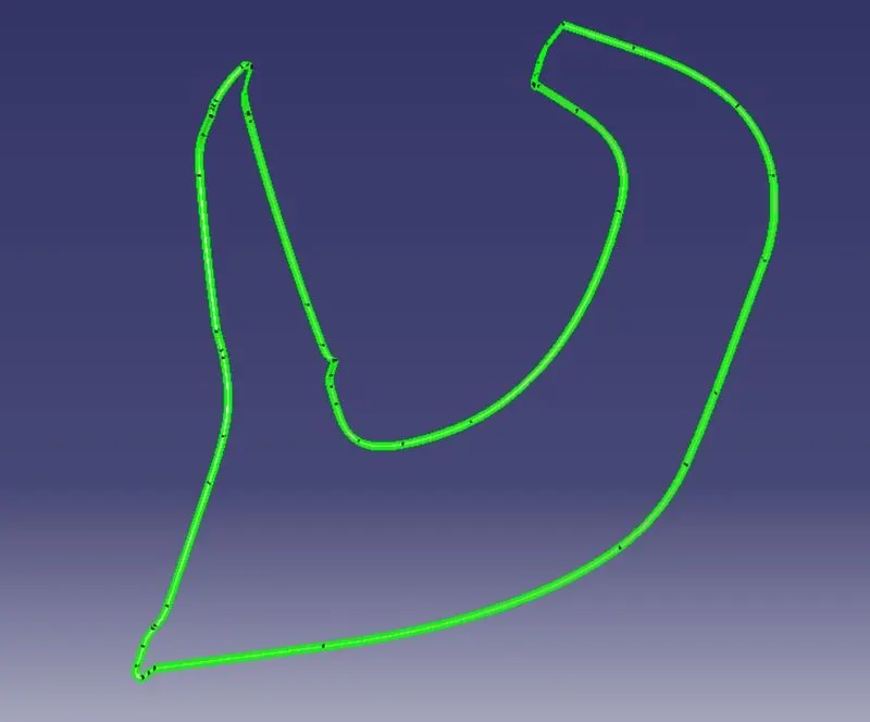
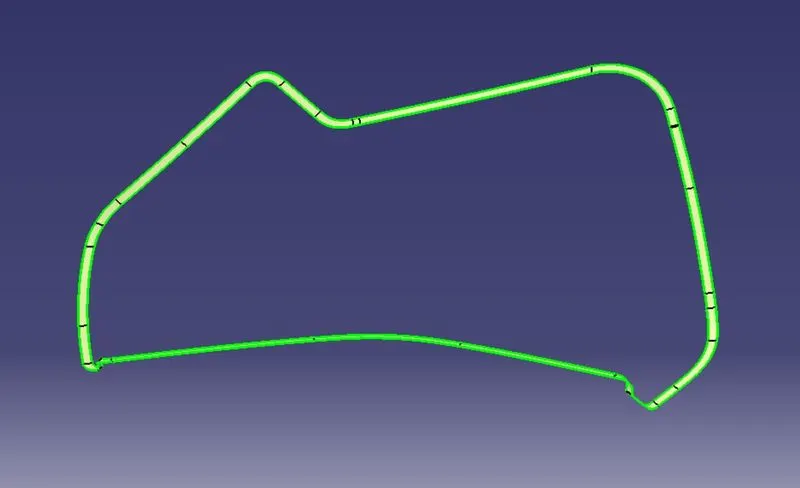
- C surface is the surface between the surface of Class A and Class B and connects them both.
- For that first we have to extract Class A boundary and then by using Sweep we select the boundary with draft direction at angle 3 degree to create the Class C surface.
1. Creation of C surface for Door arm rest
2. Creation of C surface for Map pocket
3. Creation of C surface for Lower substrate
4. Creation of C surface for Bottle holder
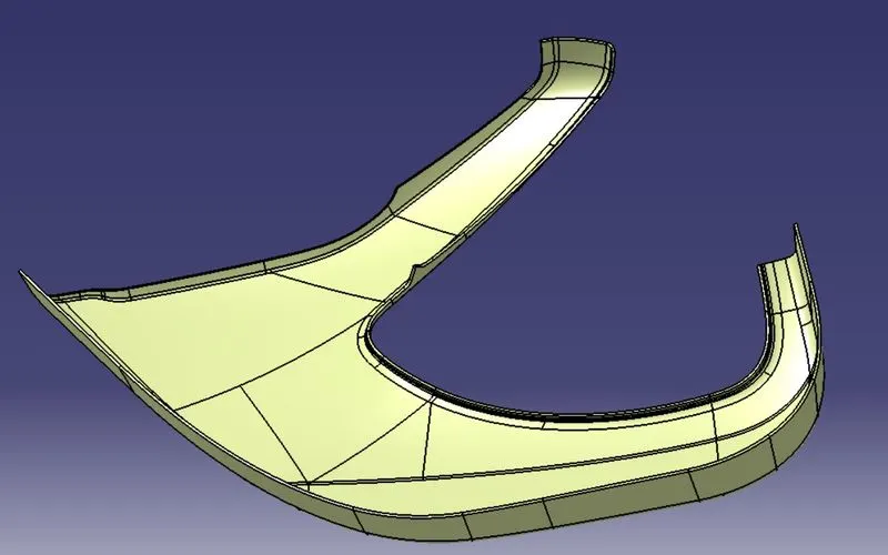
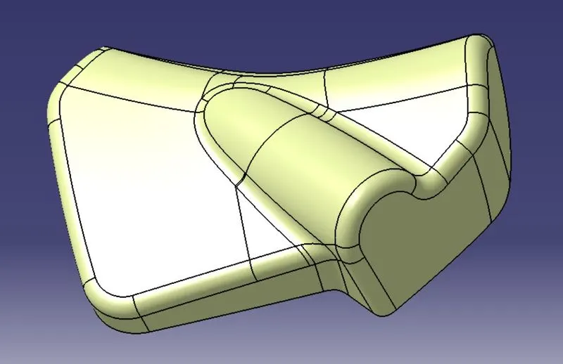
5. Final joining and trimming
- Once both the B and C surface are created we move on to the final join/trim
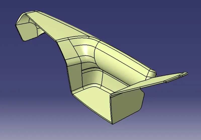
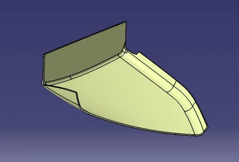
- First we join both class A and class C surface together
- Then we trim this surface with class B surface to form the final trim.
1. For Door arm rest
2. For map Pocket
3. For Lower substrate
4. Bottle holder
6. Creation of closed body
Closed body is created after the creation of final trim by the following steps;
- Make the part body 'define in work object'
- Open part design
- Click on thick surface option.
- Then click on the body
- The closed body is created.
1. For Door arm rest
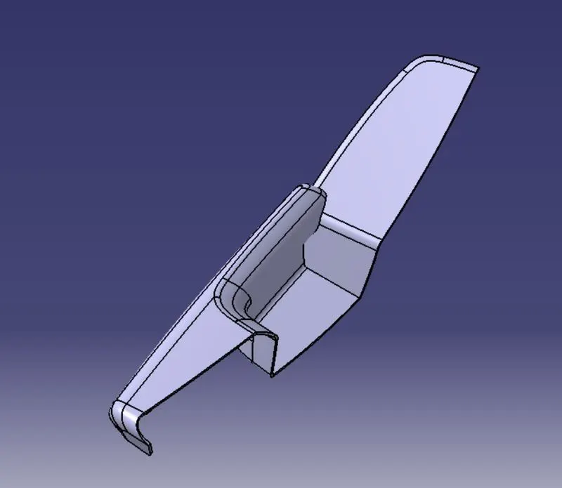
2. For map Pocket
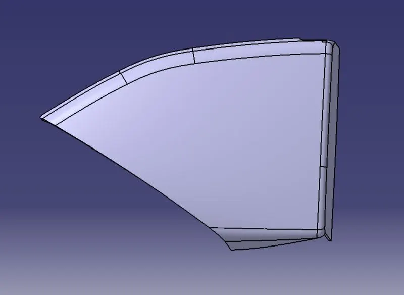
3. For Lower substrate
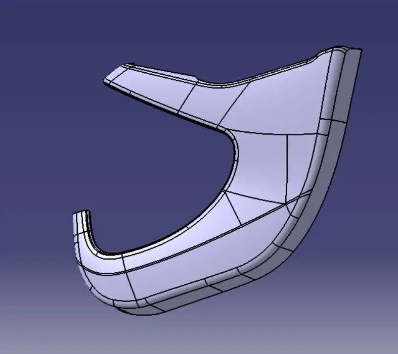
4. Bottle holder
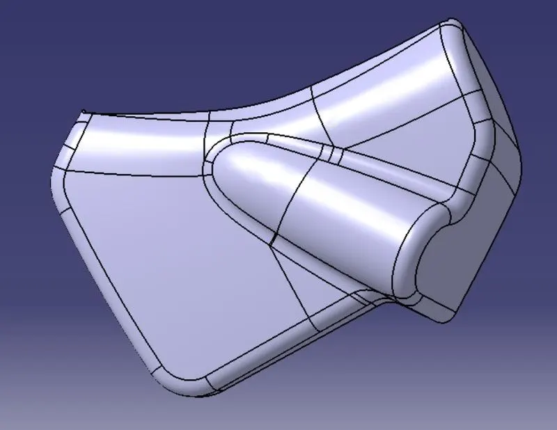
7. Creation of flanges
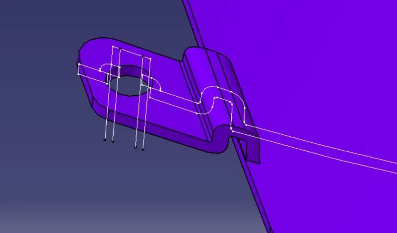
- Flanges are created by two methods; one is by following the master section given and other is by extracting required amont of C surface from the final trim body and drawing a sketch w.r.t to it with the help of intersection and points created on lower substrate for placing the heat stakes.
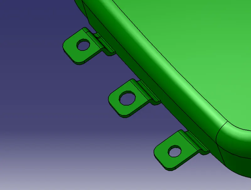
- We create numerous flanges for arm rest, bottle holder and map pocket. Even the flanges are created to accomodate heat stakes and locators
- Given below are picture of flanges created by following master section and other on created by using extract method.
8. Creation of Heat Stakes
- Heat staking combines the use of heat and pressure, to soften a specific area of the plastic enough to be remolded into a new shape or profile that forms over or around the connecting part. Once cooled, it is the plastic’s strength that holds the mating part in place.
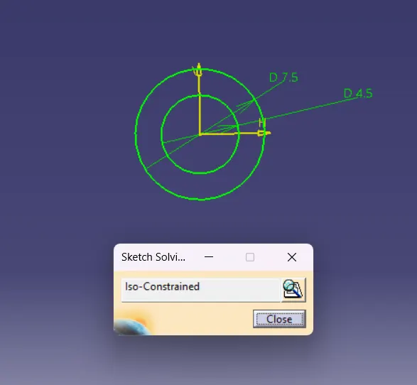
- We first draw the heat stake here with the help of the master section.
- The sketches for creation of heat stakes are;
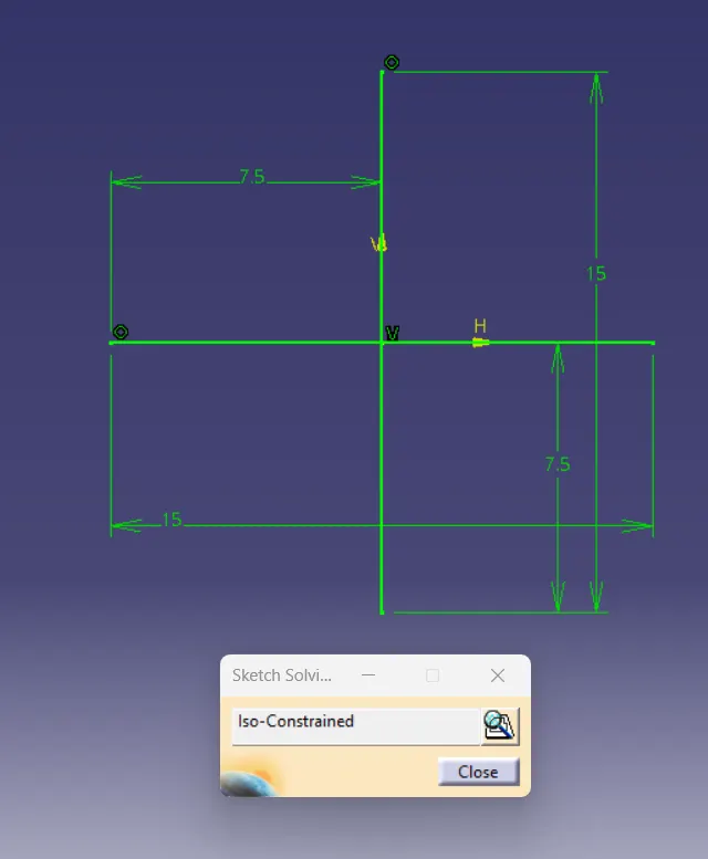
- Pad these two sketches to form the heat stake.
- There are around 14 heat stakes in the lower substrate.
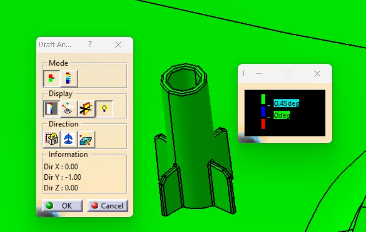
- Draft analysis done on heat stake;
9. Creation of Locators
- It is used to lock two componets during assembly
- It stops all the degrees of freedom
- The sketch for locator is given below;
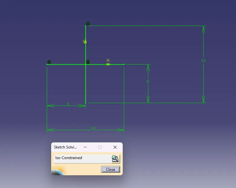
- Using pad option and nuetral element option the locators are created.
- Appropriate chamfer and fillets are given.
- A total of 3 locators are created.
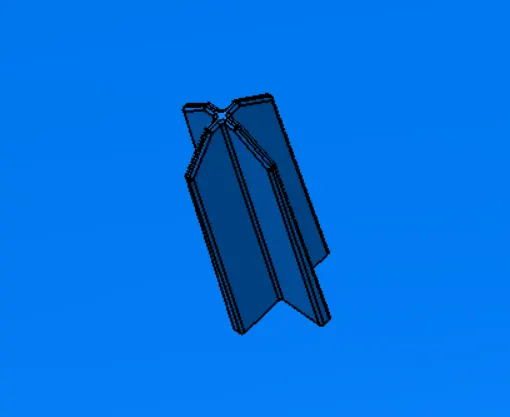
- A locator should always be taller than a heat stake since the first point of contact should be a locator.
- The results for the draft analysis is shown below;
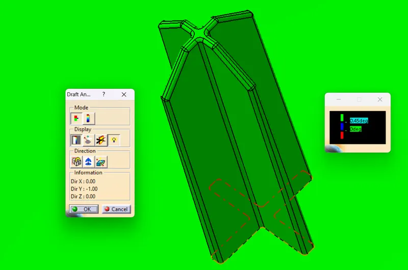
10. Creation of Dog House
- Dog house is an engineering feature used in plastic trim design. Dog houses are used as supporting feature. Sometimes other engineering features like snaps; locators etc. are mounded on them to increase their strength.
- It avoid sink marks on the main body.
The various design considerations for creating dog house are:
- Doghouse wall thickness at the intersection of the part wall (C) should be 40% or less than the main wall stock (T).
- The height of ( B ) should be between 3.0 – 6.0 mm
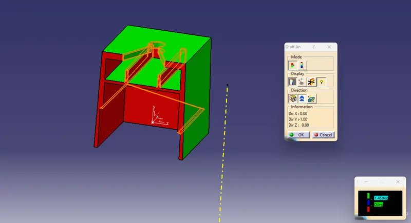
- Outer surface of dog house must have a draft angle of 3 degrees
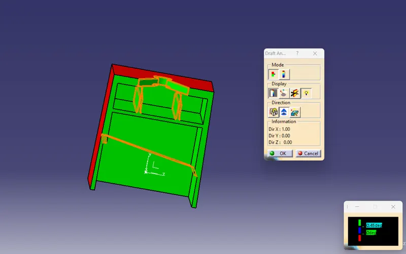
- Inner surface of dog house must have a draft angle of 0.5 degrees
The sketches for designing dog house are given below;
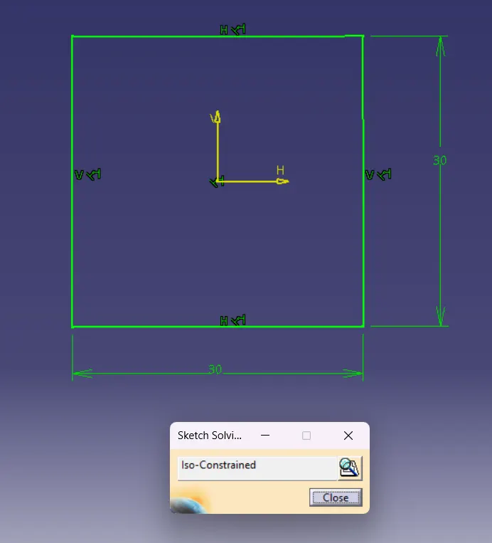
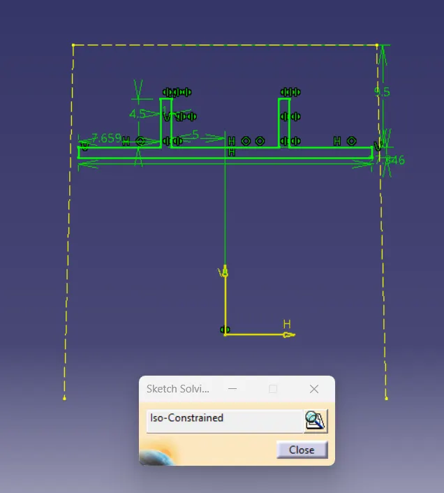
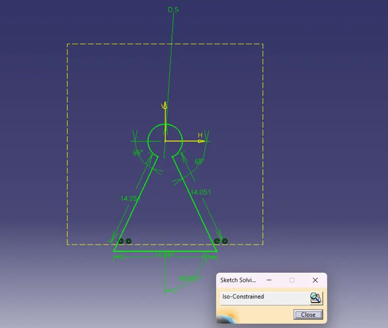
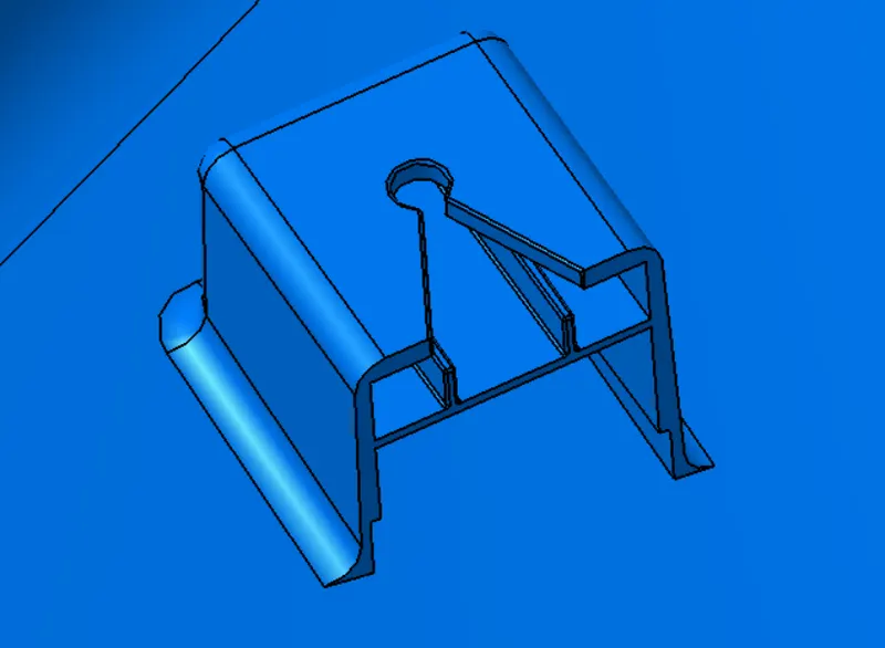
- The dog house thus created is shown below;
- Draft analysis on the outer walls of dog house is given below;
- Draft analysis on the inner walls of dog house is given below;
11. Constraining the Pushpins
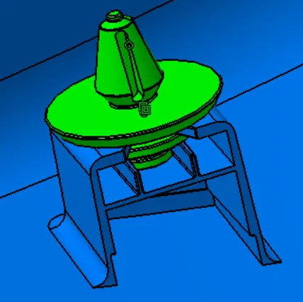
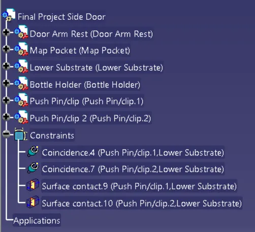
- Using coincidence constraint and contact contraint we place the push pins on top of the dog house
12. Draft Analysis on Final Body
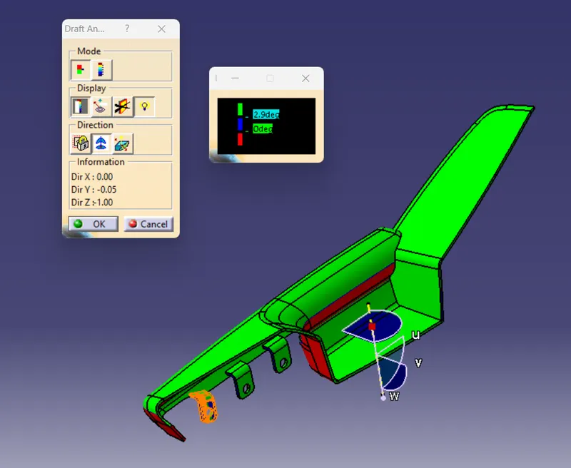
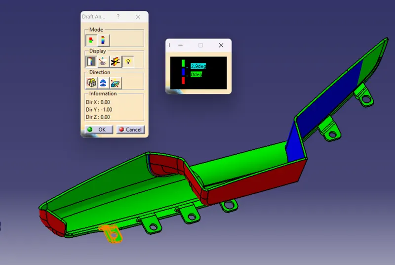
- Draft analysis is performed on the final solid body
1. For Door arm rest
- Using tooling axis
- Using side core axis
2. For Map pocket
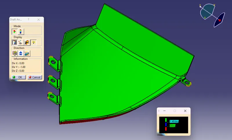
3. For Lower substrate
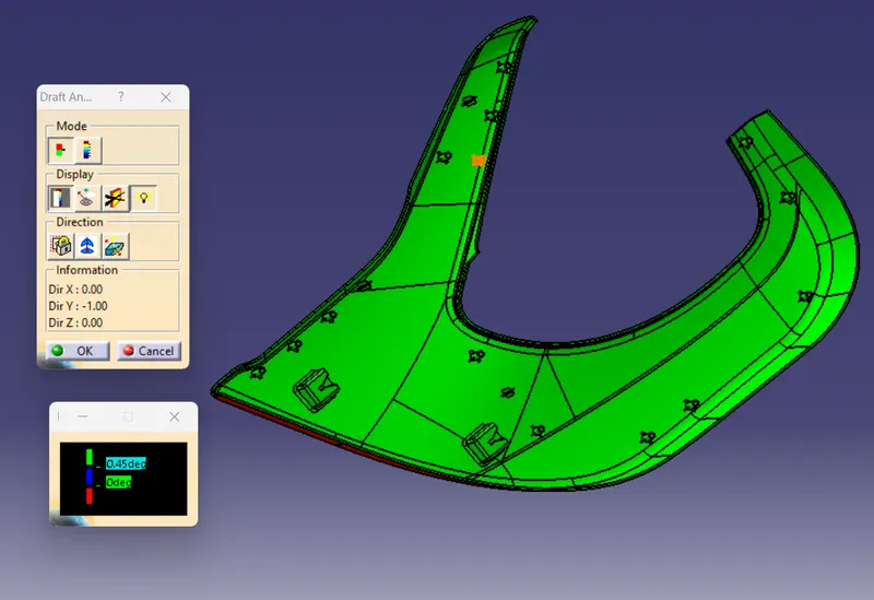
4. For Bottle holder
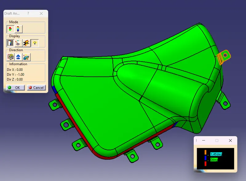
RESULTS
- CAD model for development of a Door Trim panel is developed .