Week 12- Final project
AIM
To create a CAD model for door trim panel's parts by considering the given inputs of class A surface along with master section by following the design rules followed in OEM and tier1 companies.
Objectives :-
To create individual tooling axis for the parts and perform draft analysis on the class A surface
To create the class B and class C surfaces from the given class A surface
To form a solid geometry by combining all the surfaces
To decide an attachment strategy for the part and create engineering features in reference from the master section provided
To perform draft analysis on the solid part model with all engineering features
To assemble all the components togehter to obtain the final trim
Given Data :-
Class A Surface for Door Trim Panel -
As we know in automotive industry there are complex products that we have to design but this is not possible with simple sketches for that we need Class A Surface.
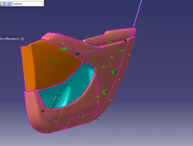
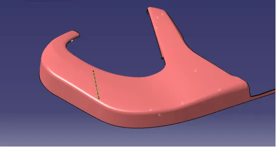
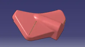
The A-surface or the styling surface is first checked for any gaps and other issues in its surfaces. This Surface acts as the input surface so any correction to be done should be with approval from the styling team or done by them. A- perfect surface is the one when a boundary is created, the lines are only on the edges of a component and its holes or cutouts as shown below.
Tooling direction
We make a point & line in on the surface on the for tooling direction
And the tooling direction depends upon the surface of draft angel given by as and then we move on the tooling direction
And the direction of compass should be an lock through the line along the surface
If the tooling direction to desired the cavity and core side of the surface
Surface 1
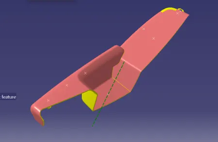
Surface 2
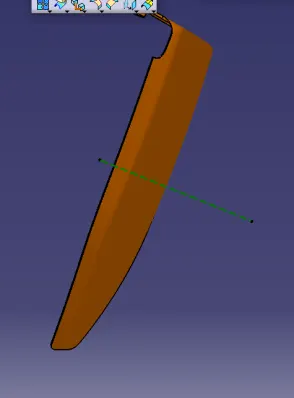
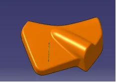
Surface 3
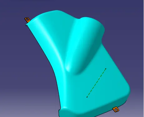
Surface 4
CLASS A SURFACE CREATION
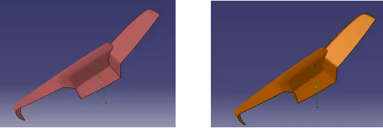
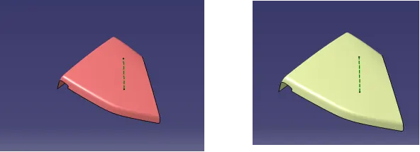
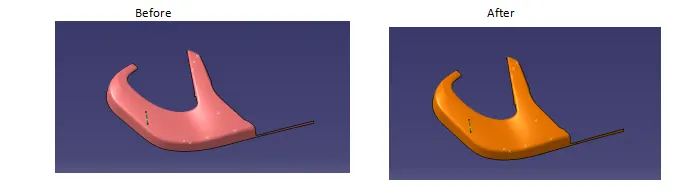
Repair the class A surface to avoid the sharp edge by using of multi- section & blend tool to make an surface patch up and then make join the surface
Surface will be copy on the main reference and open in part file and paste the separate surface in separate file
And clean smooth surface will appear
Before & After
CLASS B SURFACE CREATION
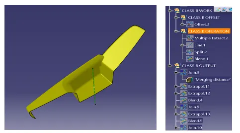
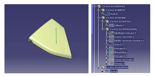
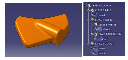
1st we start form the surface a and then offset 2.5mm from the class a toward the an z direction.
If the offset distance refer form an master section
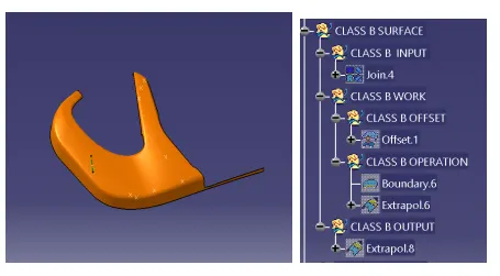
Class b surface need to work on the patch to repair using the multi section , blend , parallel curve , point etc to patch the surface
SURFACE 1
SURFACE 2
SURFACE 3
SURFACE 4
CLASS C SURFACE CREATION
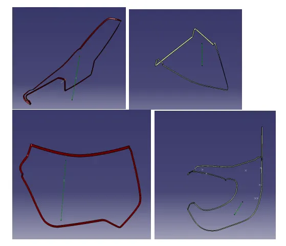
It the c surface are created by using of sweep operation with referance to normal to the surface and the angle is drat is 2 degree and select the guide curve form the class a surface boundary
CLASS C SURFACE FOR ALL THE 4 SURFACE ARE ATTACHED IN GIVEN BELOW
TRIM operation
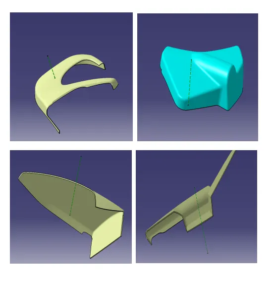
- For creating the Finals door trim surface, join the CLASS-A and CLASS-C surfaces together.
- Then Extrapolate the B surfacea little bit outward direction to make sure that there would not be any gap when trimming with the joined surface.
Then trim the extrapolated CLASS-B surface wthe ith Join surface (CLASS-A and CLASS-C)
B SIDE FEATURE CREATION
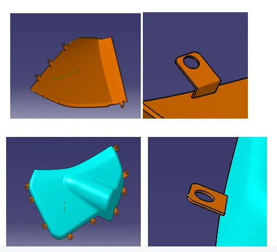
FLANGES -
Flanges are the elements that are needed to join different components together. So here I have to make flanges , Following the master section, given as the input basically the measurements and location of the flange. I have created the flanges. First I have created the flange on the outer map pocket. For creating the flanges I have taken extraction of the curve and made a point on that curve then created one plane on that point followed by creating a sketch on that plane taking the point created as the origin.
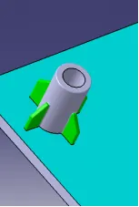
HEAT STACK CREATION
- First, create a reference plane on the B surface and draw the profile for heat stack.
- Use Pad option on part design to the sktech and pad it ti the height of about 20 mm.
- Now, use draft on the padded surface with an draft angle of about 0.5 degree.
- Then, draw a cross section lines of about 15 mm each for making the ribs for heat stack.
- Again use Pad to the sketch and use draft on it.
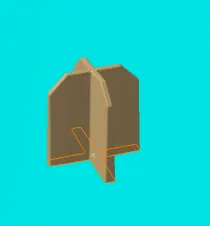
FOUR WAY LOCATOR
- Create a cross secting line of about 15 mmm each and symmetry it to the axis.
- Use Pad to the sketch of height 20 mm. And use draft on it with an angle of about 0.5 degree.
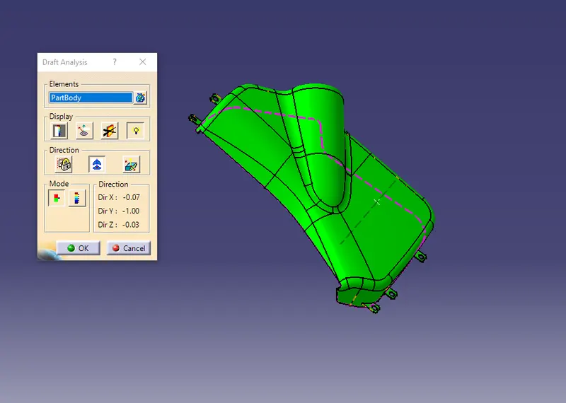
Finally, add all the engineering features to the solid component and use draft analysis to the final component.
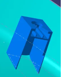
DOG HOUSE
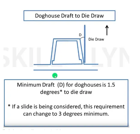
The two main purposes of a dog house are to avoid sink marks and to house various other engineering features like screw boss, locators, push clips etc.
In this case, the dog house is designed to house the push clips and the 4 way locator.
The dog house designed for the push clip features a slot on the top face to accommodate the push clip
The dog house should follow certain design rules which are stated below
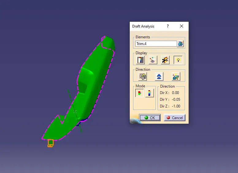
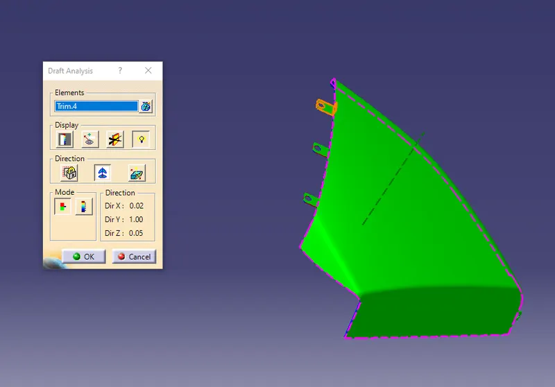
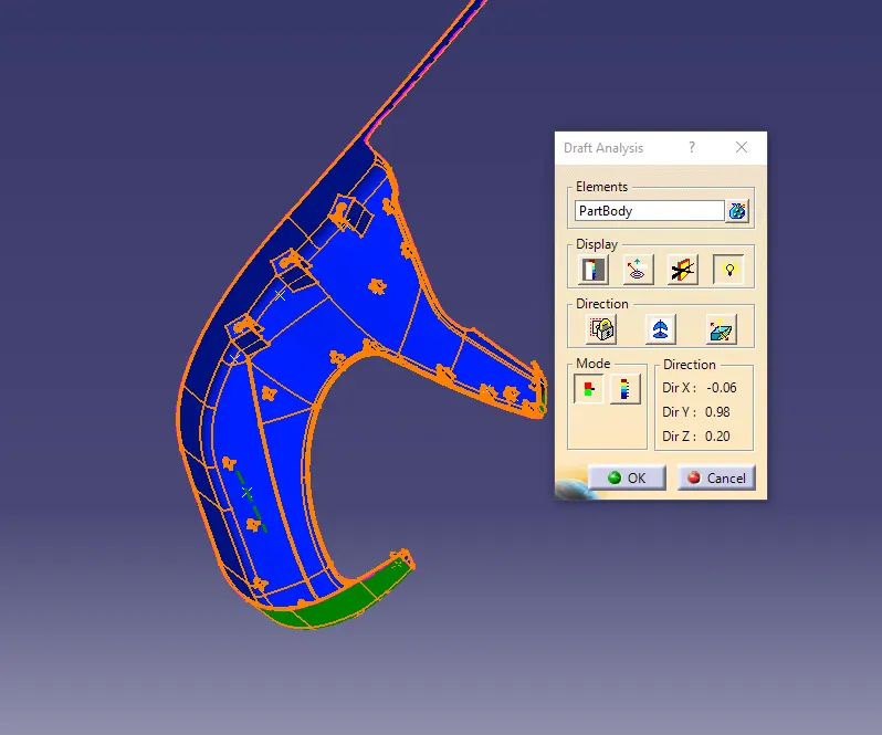
Report of draft analysis
In a draft analysis we have to position the tool direction on surface class A and the compass should be lock in the tool direction and then check the analysis under running point should check the draft angel on the surface oh the class c
If the
red represent - no draft
Green represent - positive draft on cavity side
Blue represent - negative draft on core side
Please check the report in given below attached file for draft analysis
Assembly the door trim using of top down approuch and make the assembly of door trim at zero degree of fredom
attached the image in given below
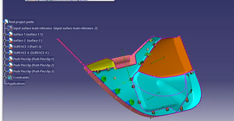
parting ling are created in given below