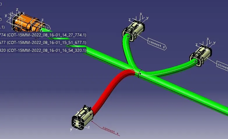
Wiring harness design in CATIA V5 - 3D modeling Week 5 & 6 Challenge
Week 5&6 project report
In this project first we start in connector to define the electrical part and next move on to create the new catalog and add the connector into the catalog
Add create the new product file and add new component to named as hardness A & hardness B
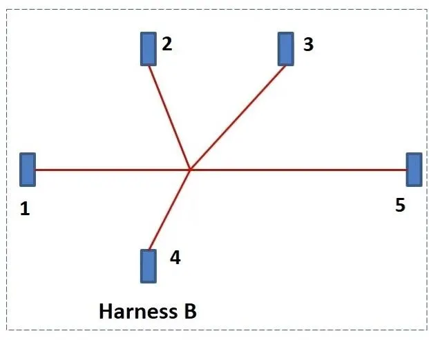
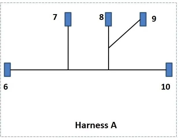
Then hardness A & B to open separate file and as per routing diagram to arrange the connector in both hardness A & B
And move on to the electrical hardness assembly work bench if the product file as to define as the geometrical bundle
And then to define the multi-branch able to the main connector and we add the branch point on required position to adjust the length & ratio of the main branch to split up
If they branch definition option to select and start first in the starting bundle and connector.
All the connector are add to the main branch of both hardness A &B
Then move on to the electrical assembly work bench and the inter link the both A & B.
if electrical definition method to use link device option
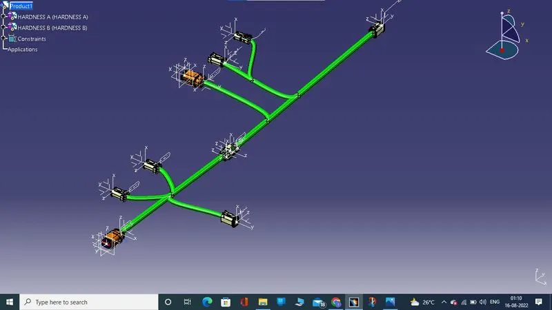
with protective device
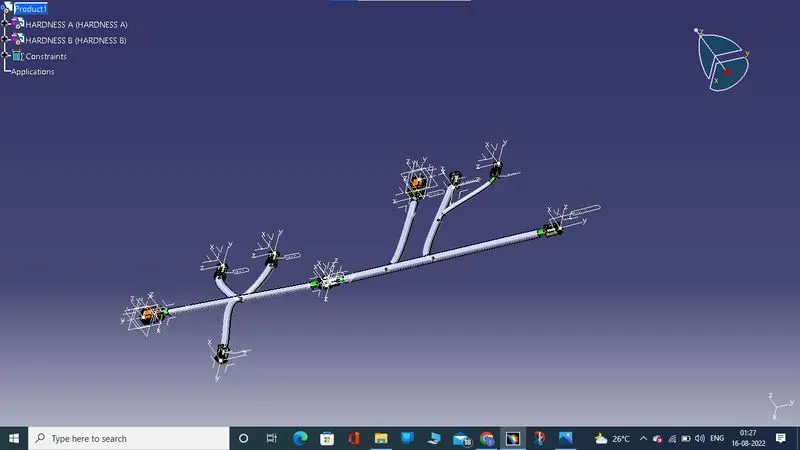
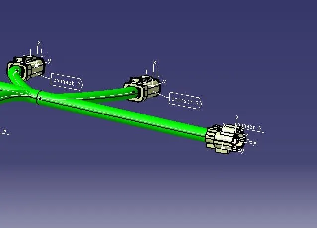
Once before the installation to give the connector 3D annotation
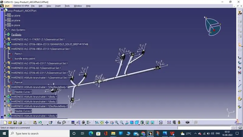
If the CATpart file is to be used in catia software so drawing is and universal language so we going to convert the part as igs , stp file using the option of generate catpart file product all at all type of is convert.
If the convert the file and save into various form like igs, stp, catpart , etc
we check the bundle continuety using the search option choose electrical and bundle segment and fully connected
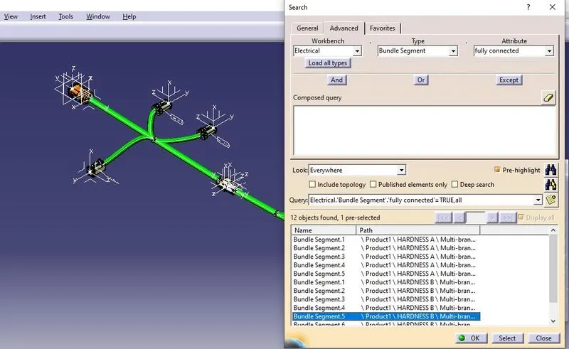
to check bunddle error