Wiring harness routing & packaging Rules Week 3 Challenge
1QUESTION
Download following cad data & define it as Electrical support using Electrical Part design Workbench. Define all the necessary properties.
clamp is the devices to support the bundle at required location. its can possible as both existing ways act as entry and exit based on meting surface of the system
Procedure
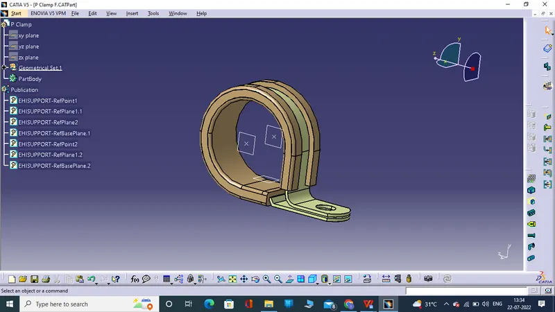
To download the P-clamp as source of TE.com and the open p-clamp in catia v5 , move on to part design then create the midpoint of both entry and exit way and create the plane at entry face, exit face and base of the plane and save it
Then move on to electrical part design to determine the P-clamp as electrical supporting device so we click the supporting part icon and the select the P-clamp name as your wish. then select reference point 1 and plane one and second entry way we only choose 2 plane and select base plane of the meting surface at reference plane. At the same procedure can repeat in another entry ways as electrical definition.
Screenshot of P-Clamp
2) Question
Download following Back shell cad data & define it as Electrical back shell using Electrical Part design Workbench. Define all the necessary properties.
Tyco 1738312-1
Black shell is the device to protect the bundle area of bundle connection point it has various type to protect
Procedure
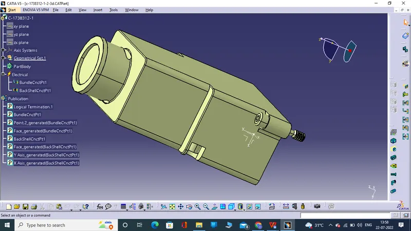
Open Tyco 1738312-1 and move on to part design . to deterimne the midpoint of the bundle connection area and at same time to determine the midpoint of black shell and axis system of black shell to find referance point and the x-axis to rotate at 90 degree , y-axis facing meting dircetion &z-axis are in reverse dircetion .
Once the geomentrical set completed and move to electrical part bench .
To define the given black shell is an electrical component and then to determine the bundle connection point and black shell connection point .
Once they above following procedure are completed to define a black shell is a electrical component
Screen shot tyco 1738312-1
3) Question
Create Following Corrugated tubes & Add them in Catalogue under “Slit COT” family.
|
Name |
ID (mm) |
OD (mm) |
Thickness (mm) |
|
15mm COT |
12 |
15 |
1.5 |
|
20mm COT |
17 |
20 |
1.5 |
|
35mm COT |
32 |
35 |
1.5 |
|
10mm COT |
7 |
10 |
1.5 |
|
5mm COT |
3 |
5 |
1 |
Corrugated tube is a device used to protect the electical bundle or insulate the bundle and improve the hardness . it is protection device of electrical system.
Procedure
Fist of all we create the catalog for cot tube .
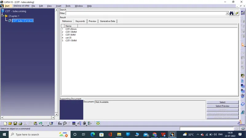
Open new and select the catalog doctement and add family name as cot tube and click ok to save at required location
And we create various cot tube at various size are 35, 20, 15, 10 & 5 all are in mm using electrical part design work bench .
Open protecting devices select plane of the work bench new dialouge box fill and click ok we create cot tube
For example to create cot tube
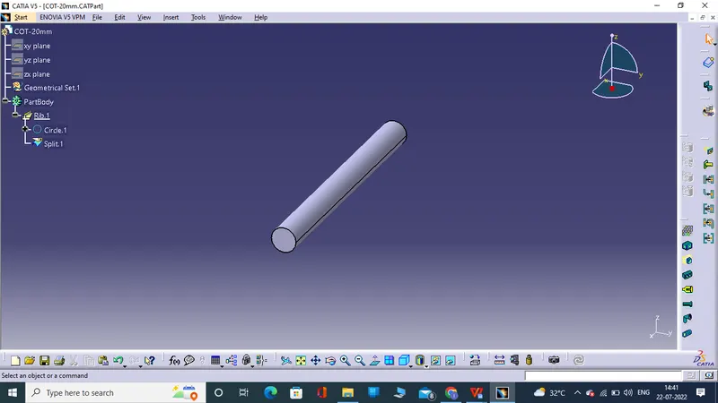
Name of cot- cot -20mm
Type - cot tube
Inner dia - 17mm
Crocess area - auto calculated
Thickness - 1.5mm
Bend radius - 1.5 time’s of ID
And the click ok we create cot tube at 20mm
Scree shot for your reference catalog and cot 20 mm
Adding catalog of cot tube
Create cot tube-20mm