Week 12- Final project
Aim:
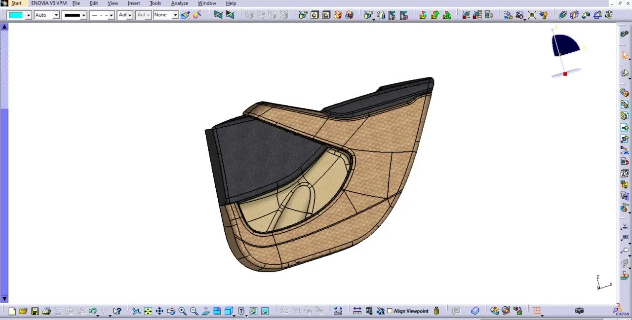
The objective is to design and produce a roust side door trim for car utilizing the specified class of materials, The door trim consists of four key components : Lower substrate, Bottle holder, Map pocket & Door arm-rest.Also some B- side components such as locators, heat stakes & doghouse which must meet design requirements.
The Role of Plastics in the Automotive Sector: Plastics contributing to the creation of vehicles that are lighter more fuel efficient and cost effective. As the third largest consumer of polymers after packinging and construction the automotive industry heavily relies on plastics for functional performace and safety elements in vehicles. In automotive sector plastics replace heavier materials like metals. This shift not only reduces weight but also improved fuel efficiency and lower carbon emissions.
Plastic Components in Vehicles: A typical vehicle comprises about 30000 parts with approximately one third of these made from th plastic components include essential vechicle parts like bumpers ,interior panels, dashboards and engine components.
Types of Plastics Used: A total of 39 different types of plastics and polymers are utilized in the automotive industry. The four primary plastics polypropylene (PP), polyurethane (PU), polyamides (PA), and polyvinyl chloride (PVC) account for over 70% of the plastics used in vehicles.
Lightweighting in the Automotive Industry: Lightweighting is a key factor in increasing fuel efficiency, which is directly linked to the growing use of plastics. By substituting heavier materials with plastics, manufacturers can reduce a vehicles overall weight, resulting in improved fuel consumption and better compliance with environmental regulations.
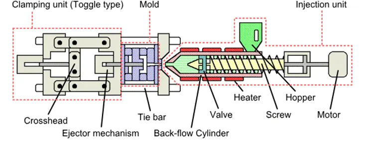
Manufacturing Process: Injection Molding Injection molding is a versatile and highly efficient manufacturing technique widely used in the automotive industry to produce plastic components. During this process, plastic pellets are melted and injected under high pressure into molds to form specific shapes. After cooling and solidification, the molded plastic part is ejected.
This process allows for the mass production of high-quality, precise automotive parts. In injection molding, raw plastic is heated until it becomes malleable and then injected into a mold cavity under pressure. The mold is then cooled, solidifying the part, which is ejected once hardened.
Key Steps in Injection Molding:
Melting Plastic Pellets: The plastic is heated to a malleable state.
Injection into Mold: The molten plastic is injected into a mold cavity at high pressure.
Cooling and Ejection: After filling the mold, the plastic cools and solidifies before being ejected from the mold.
Injection molding is especially suited for the automotive sector, where it enables the mass production of durable and accurate parts required to meet stringent safety and performance standards.
Tooling and Design Considerations: The direction in which the mold opens and closes is called the Tooling Direction. This determines the design of the mold and how it will be pulled apart to release the finished part. The mold consists of two primary components:
Core: The male part of the mold that forms internal features.
Cavity: The female part of the mold that shapes the external features.
The Parting Line is the visible seam where the core and cavity meet.
Design for Manufacturing and Assembly (DFMA): DFMA is a design methodology aimed at reducing production time and cost by optimizing both individual part designs for ease of manufacturing and overall assembly designs for efficient integration.
Components of DFMA:
Design for Manufacturing (DFM): Focuses on selecting cost-effective materials, minimizing complexity, and reducing production time.
Design for Assembly (DFA): Simplifies the assembly process by reducing the number of parts and ensuring ease of integration.
The primary goal of DFMA is to streamline the entire product lifecycle, from design to production, increasing efficiency and reducing overall manufacturing costs.
Step-by-Step Guide to Plastic Product Design and Tooling Axis Creation
Step 1: Understand Surface Classifications (A, B, and C)
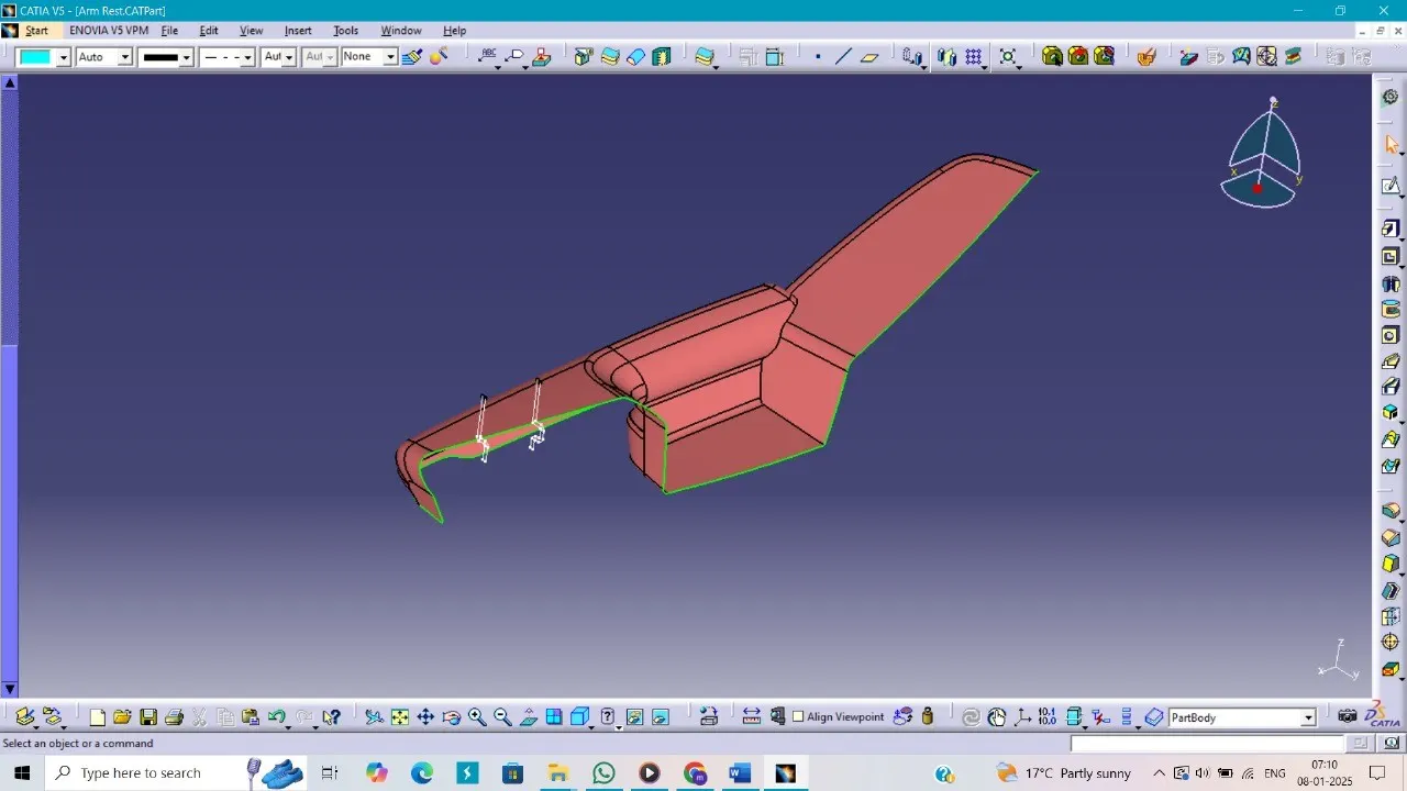
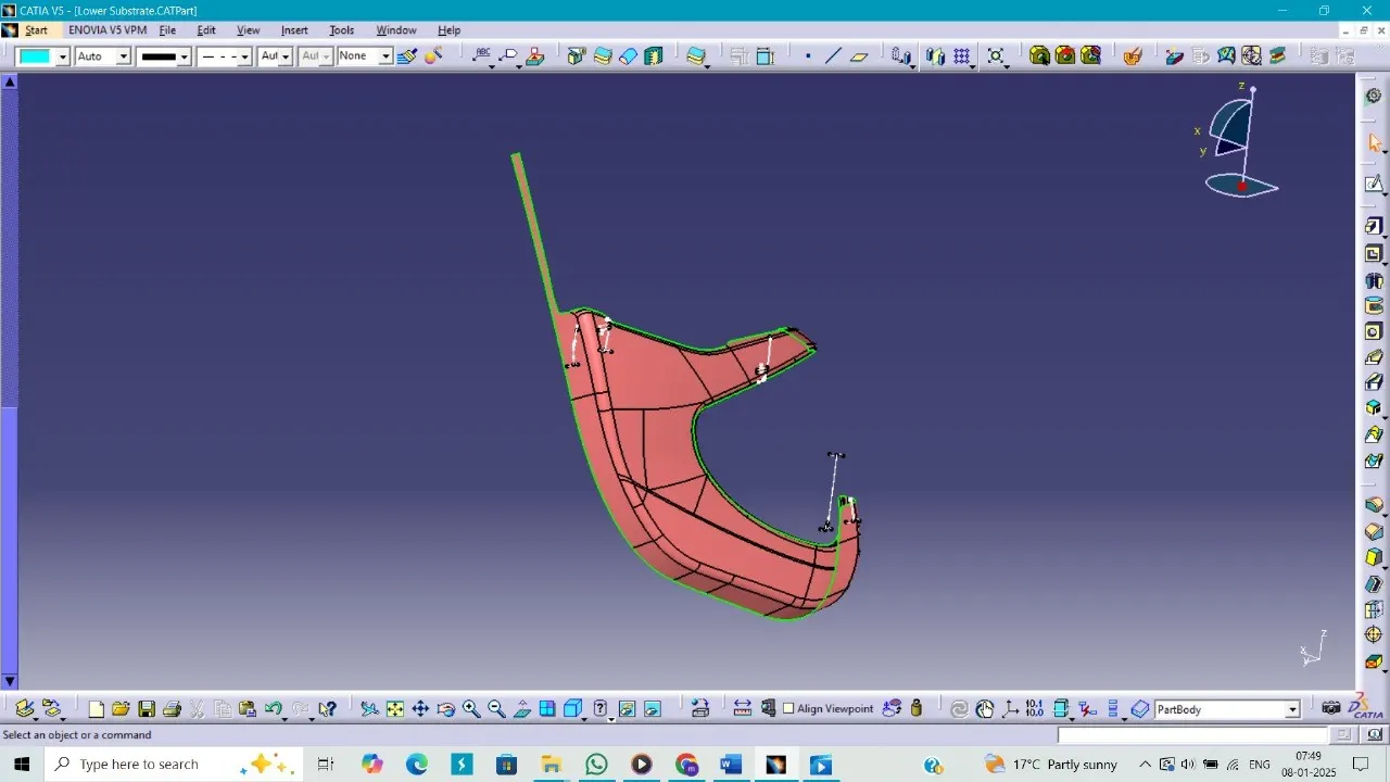
Class A Surface: Class A surfaces are the outer cosmetic surfaces of a plastic product that are visible once the product is completed. These surfaces must have the highest quality finish to maintain the product's aesthetic appeal.
Design Considerations: These surfaces should be smooth and free from any defects, scratches, or tool marks. The appearance of Class A surfaces often defines the product’s look and feel.
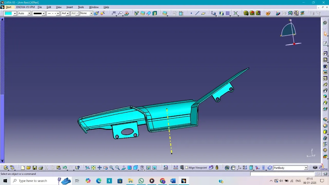
Arm Rest
Lower Substrate
Map Pocket Garnish

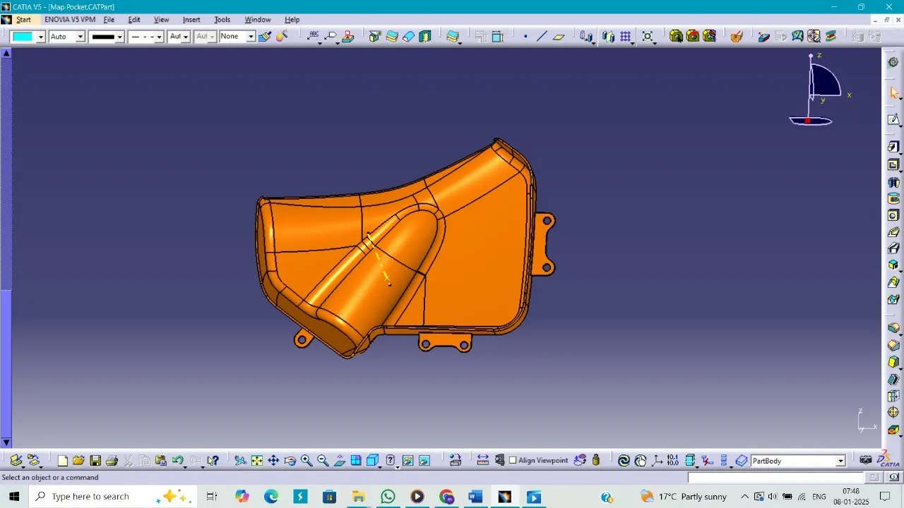
Map Pocket
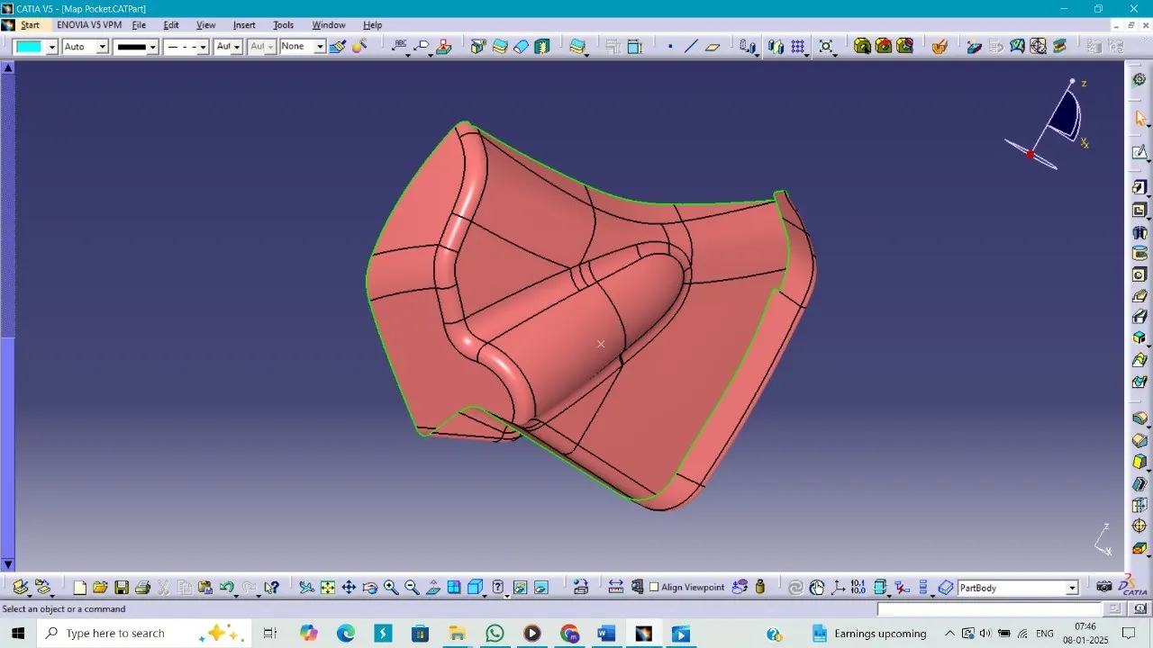
Class B Surface: Class B surfaces are the non-visible, functional areas of the part. While they are essential for the assembly and performance of the product, they don’t need the same level of finish as Class A surfaces.
Design Considerations: Class B surfaces focus on functionality and ease of manufacturing but are not exposed in the final product.
Class C Surface: Class C surfaces usually involve features that don't form part of the external or internal design, such as draft angles, undercuts, and other elements that aren’t critical to the product’s appearance.
Design Considerations: These surfaces often prioritize functionality over appearance and are typically hidden during assembly.
Step 2: Design and Model the Part
The part should be designed in CAD software like CATIA, considering the following:
Draft Angles: Ensure that the mold can easily release the part, with typical draft angles of 1-3° on most surfaces.
Wall Thickness: Maintain uniform thickness to avoid molding issues like warping or sink marks.
Radii and Fillets: Add proper fillet radii to reduce stress concentrations and ensure smooth material flow.
Undercuts: Avoid undercuts unless they are necessary, as they complicate the mold design.
Step 3: Create the Tooling Axis
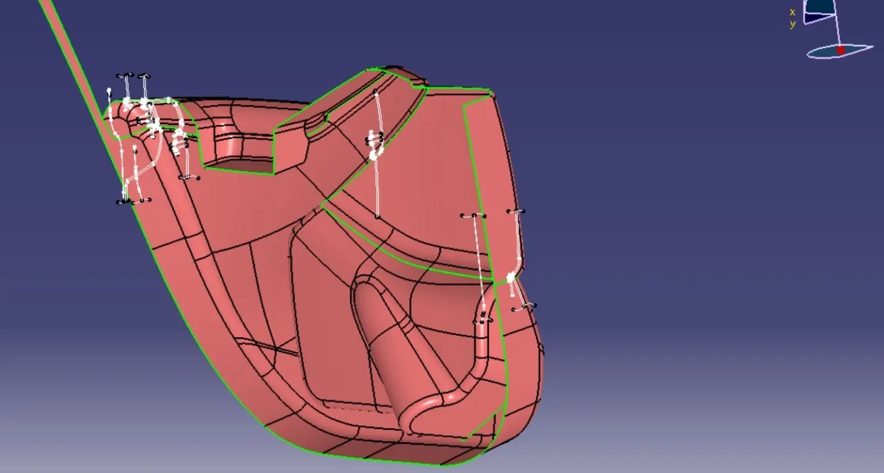
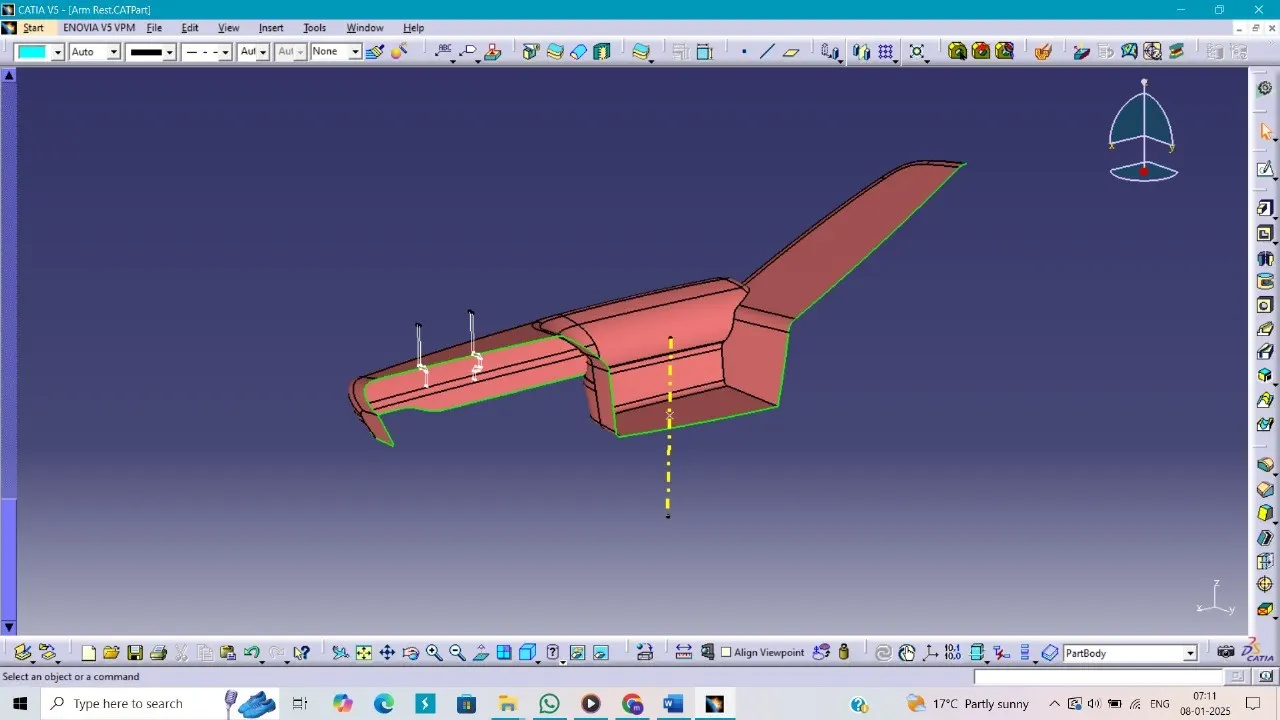
The tooling axis is essential for the mold’s operation and determines the direction in which the part will be ejected. Here’s how to define it:
Main Direction of Mold Opening: Typically aligns with the longest axis of the part, and it’s often perpendicular to the parting line.
Tooling Axis Based on Parting Line: Align the axis in a way that facilitates easy part ejection along the parting line.
Draft Angles Consideration: The tooling axis should support the draft angles and avoid part sticking.
Symmetry Check: If the part is symmetrical, the tooling axis can be aligned with this symmetry for improved molding efficiency.
Class A Surface Validation: The tooling axis must be aligned in a way that ensures the Class A surface is molded accurately.
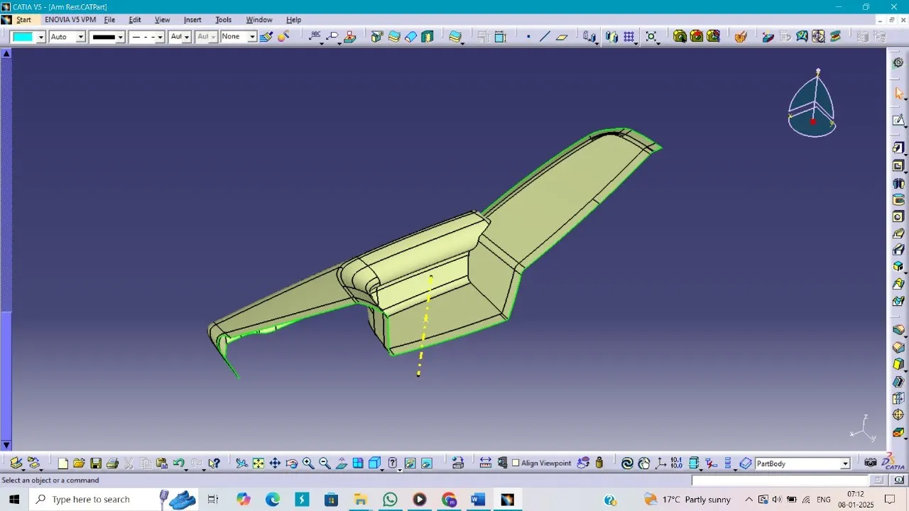
Arm Rest
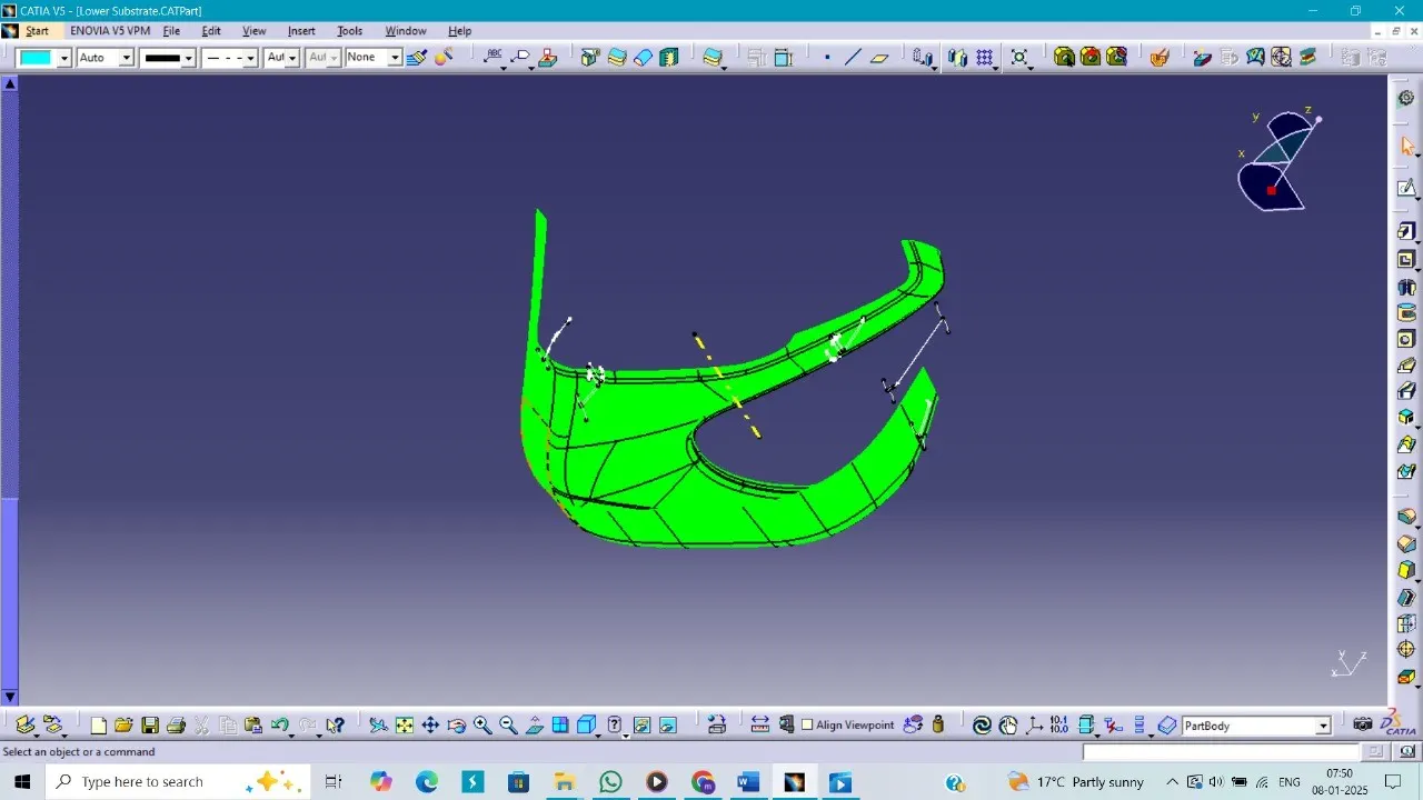
Lower Substrate
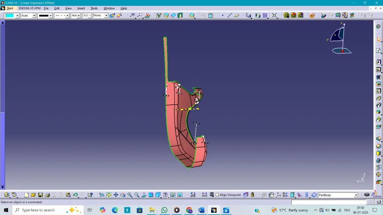
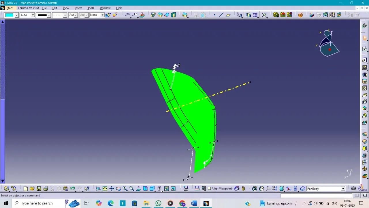
Map Pocket Garnish
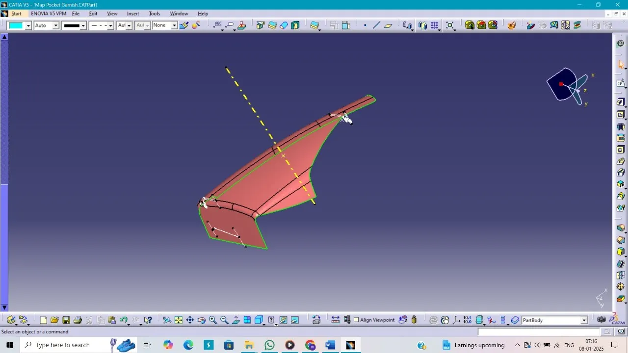
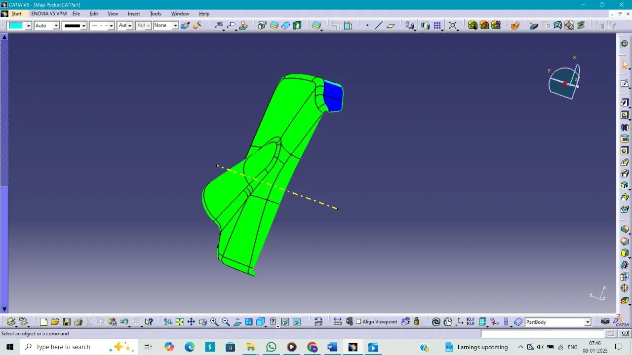
Map Pocket
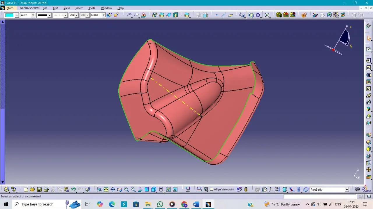
Step 4: Validate the Tooling Axis
Once the tooling axis is defined, it’s important to validate it:
Visualization: In CAD, confirm the draft angles are applied correctly.
Flow Analysis: Perform simulations to ensure plastic flows evenly during molding, especially for complex or thin-walled parts.
Arm Rest
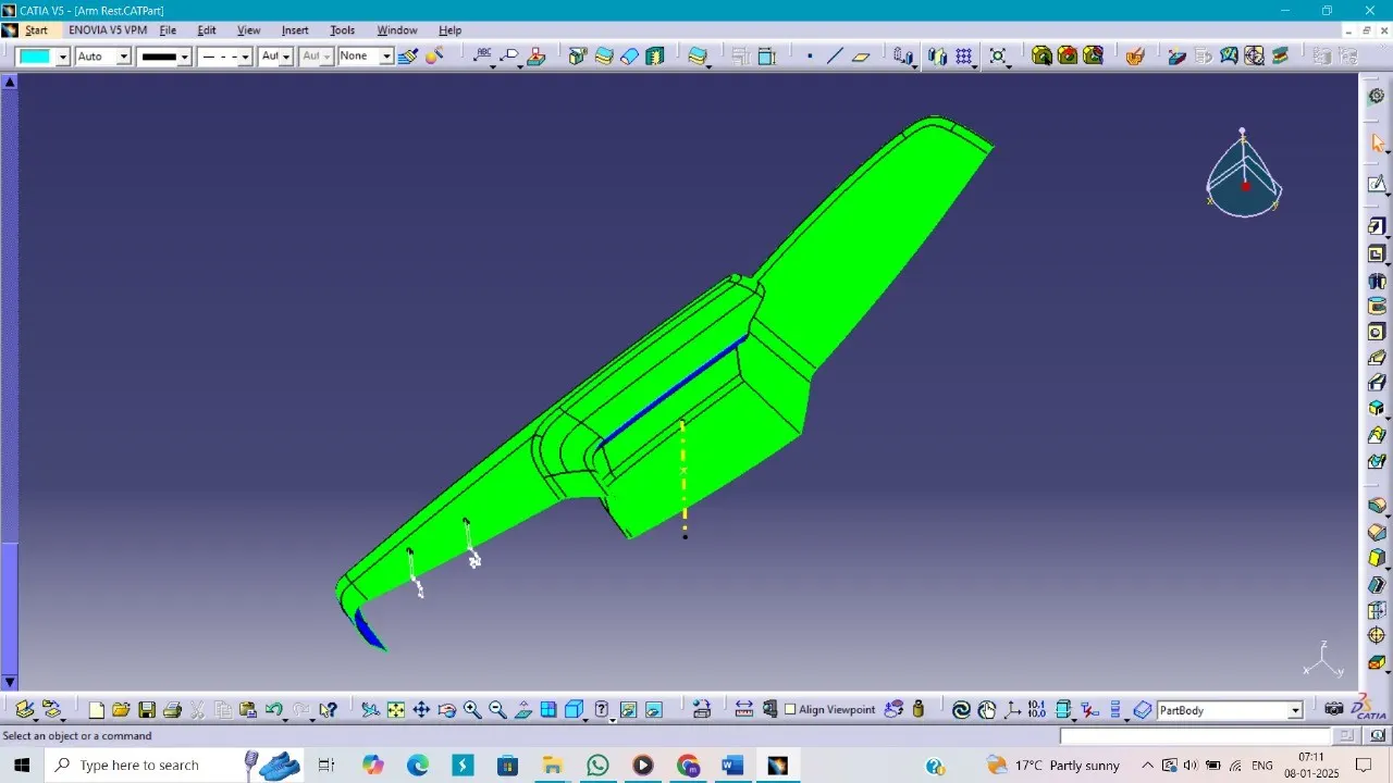
Lower Substrate
Map Pocket Garnish
Map Pocket
Step 5: Perform Draft Analysis
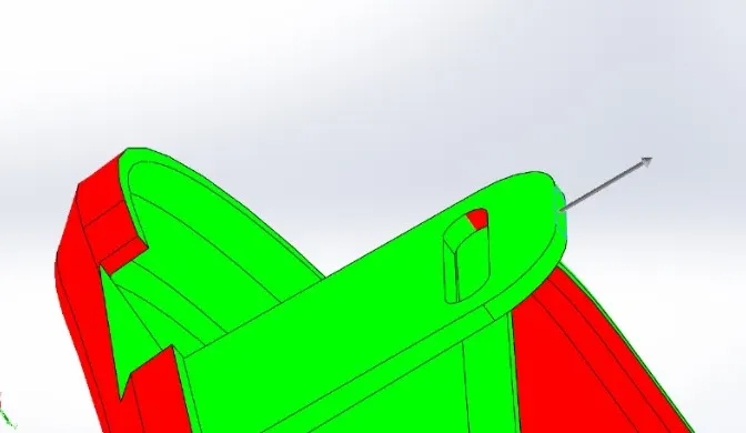
After setting the tooling axis, draft analysis ensures that the part can be easily ejected from the mold. The analysis uses color coding:
Green: Indicates a sufficient draft angle (>3°).
Blue: Indicates a negative draft, which can result in molding issues.
Arm Rest
Lower Substrate
Map Pocket Garnish
Map Pocket
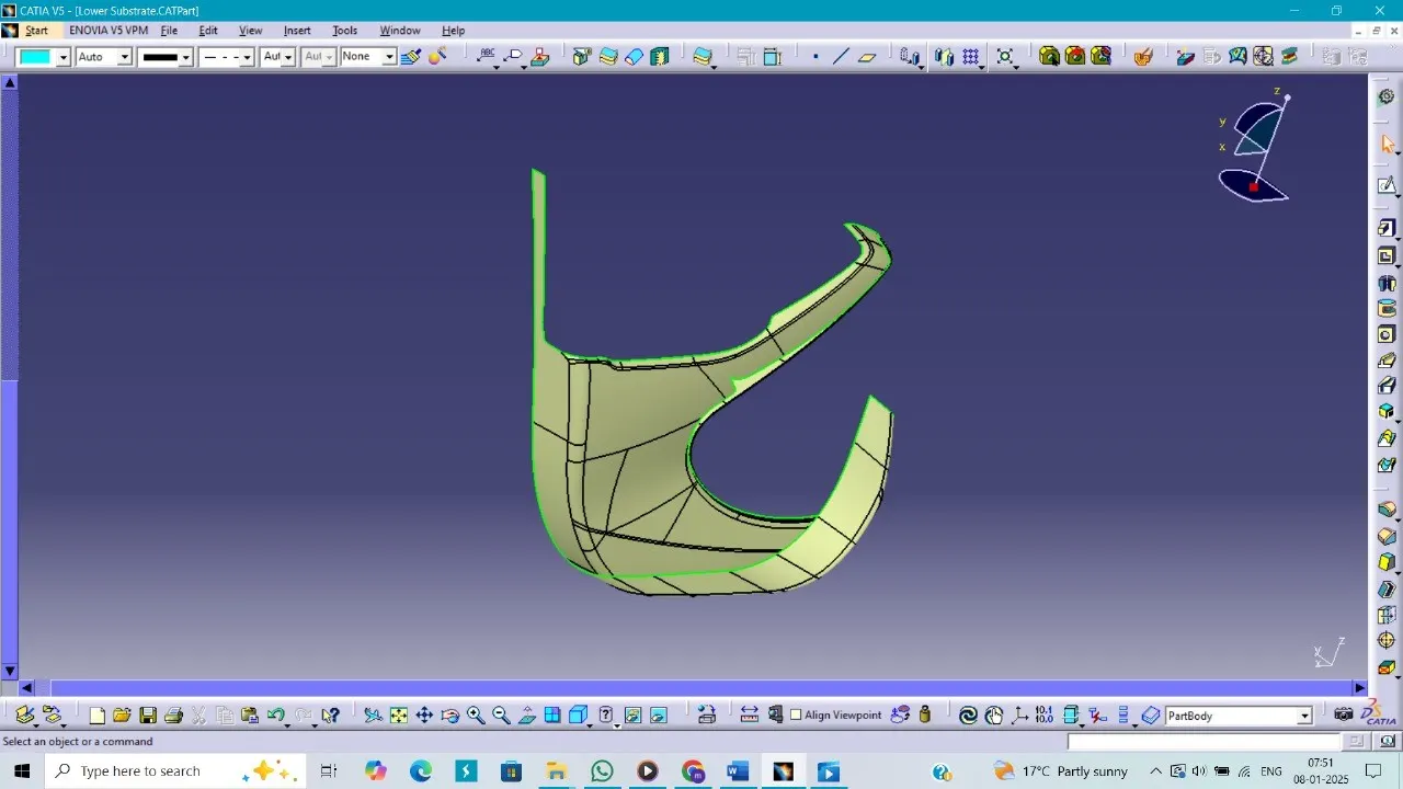
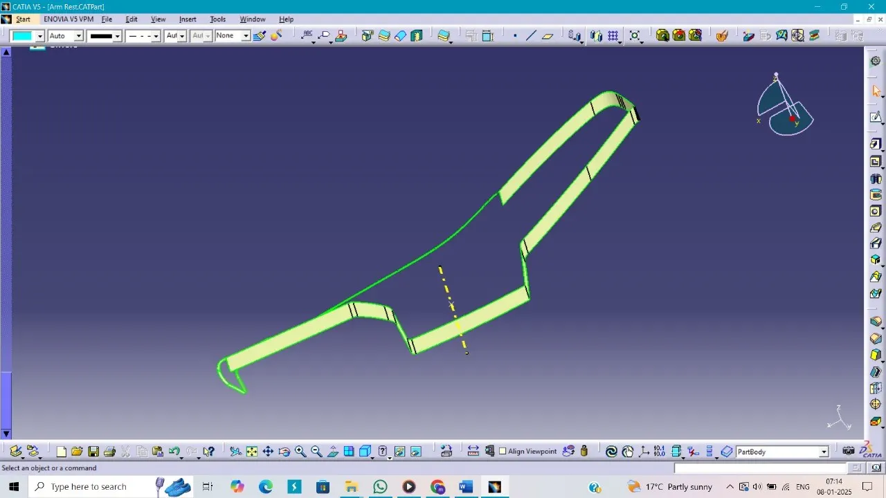
Step 6: Create Class A, B, and C Surfaces
Class A Surface: Focus on creating the outer surfaces that are aesthetically critical. These should be smooth and flawless.
Class B Surface: This internal surface forms the core of the mold. Careful planning of fillets and offsets is necessary.
Arm Rest
Lower Substrate
Map Pocket Garnish
Map Pocket
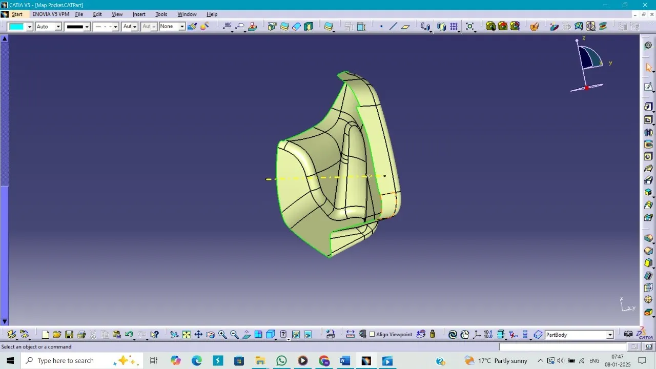
Class C Surface: These secondary surfaces help close the mold cavity. They are trimmed and joined to complete the part design.
Arm Rest
Lower Substrate
Map Pocket Garnish
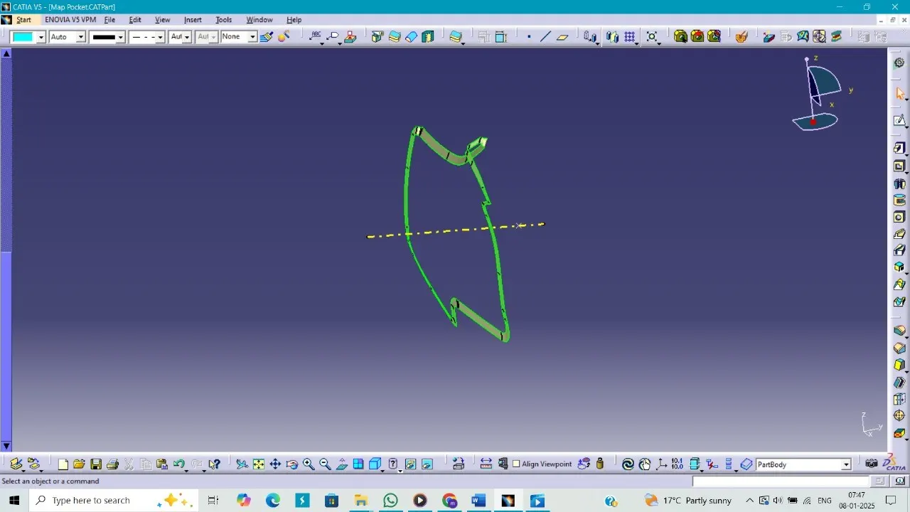
Map Pocket
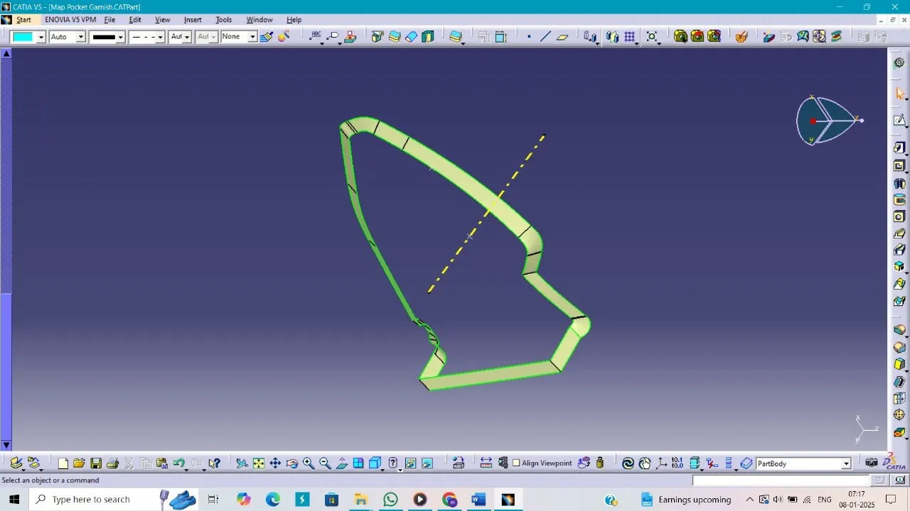
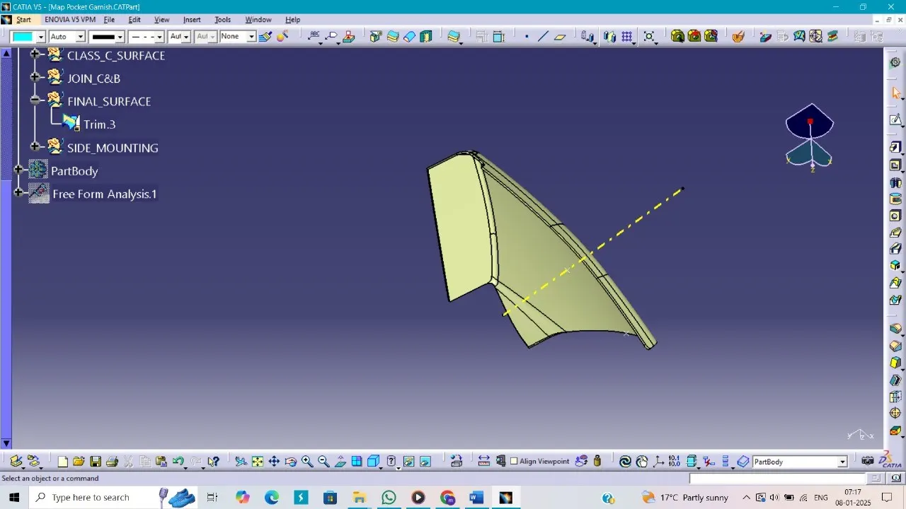
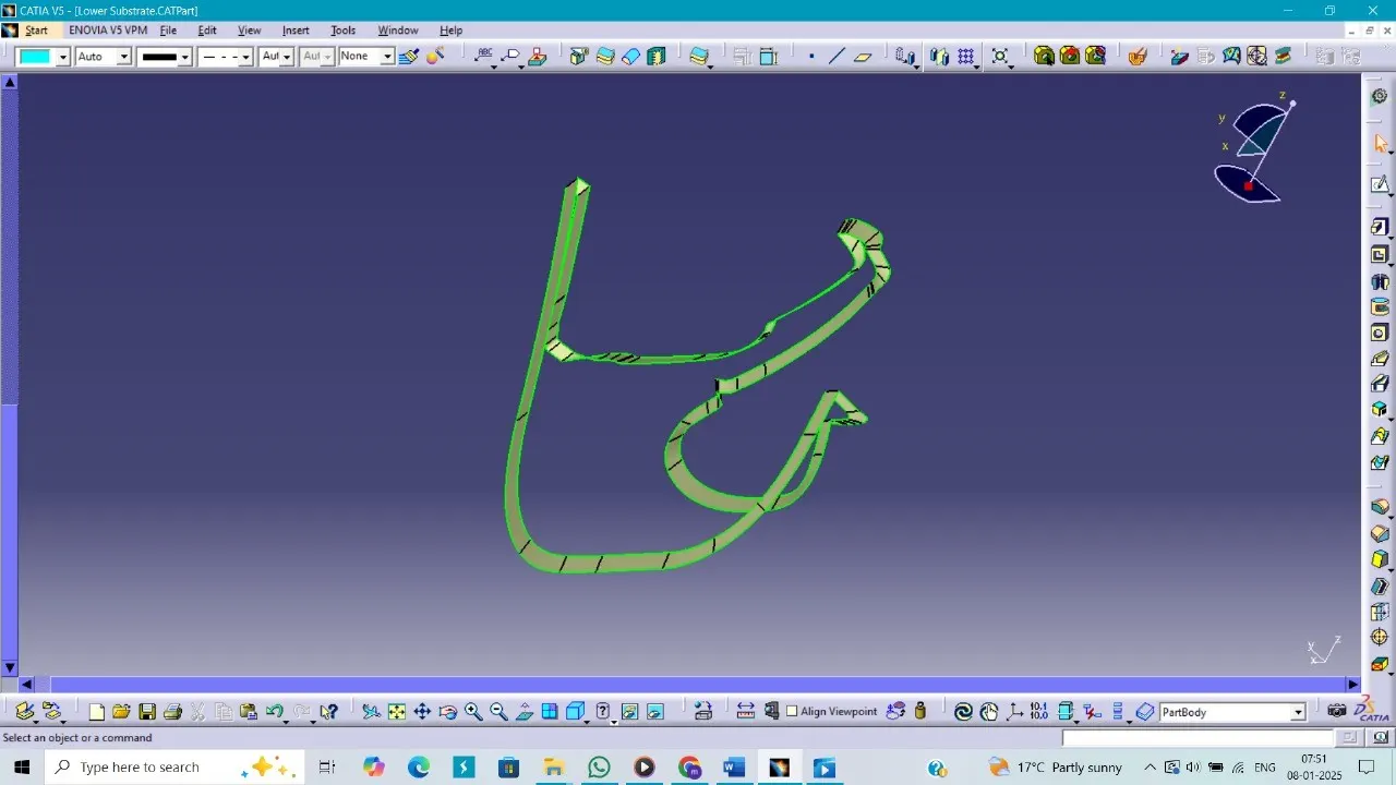
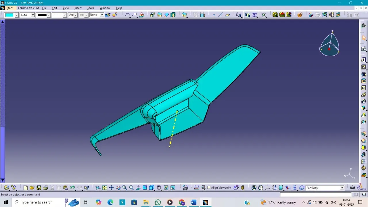
Step 7: Final Surface Assembly
Once all surfaces are designed, the final step involves trimming and joining the A, B, and C surfaces to form the complete part shape for molding.
Arm Rest
Lower Substrate

Map Pocket Garnish
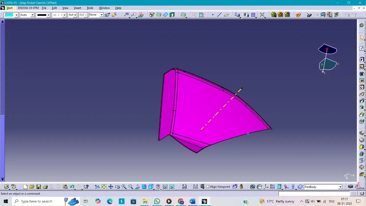
Map Pocket
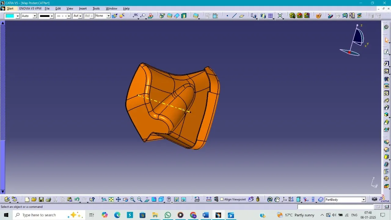
Step 8: Surface Thickening
Before finalizing, the part surface is thickened to meet the required specifications. This is typically done in the part design workbench to ensure structural integrity.
Arm Rest
Lower Substrate
Map Pocket Garnish
Map Pocket
Heat Staking
Heat staking is a method used to join plastic parts by applying heat to soften the material, allowing it to bond securely with another component, such as metal or plastic. This process is commonly used in industries like automotive, consumer electronics, and medical devices.
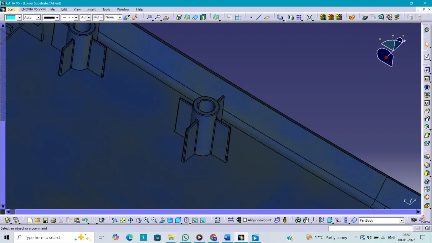
Benefits and Characteristics of Heat Staking:
- Joining Dissimilar Materials: Heat staking effectively joins materials like metal-to-metal, plastic-to-plastic, and metal-to-plastic.
- Accurate Control: The process is precisely controlled, providing consistent results within a narrow process window.
- Localized Heating: Heat is applied locally, preventing damage to surrounding materials, which is ideal for heat-sensitive parts.
- Design Flexibility: Custom tools allow for various heat-stake shapes tailored to specific component requirements.
- No Vibration: Unlike methods like ultrasonic welding, heat staking doesn’t involve mechanical vibration, making it suitable for sensitive materials.
- Processing Glass-Filled Materials: Heat staking can process glass-filled plastics, commonly used in automotive and industrial components for added strength.
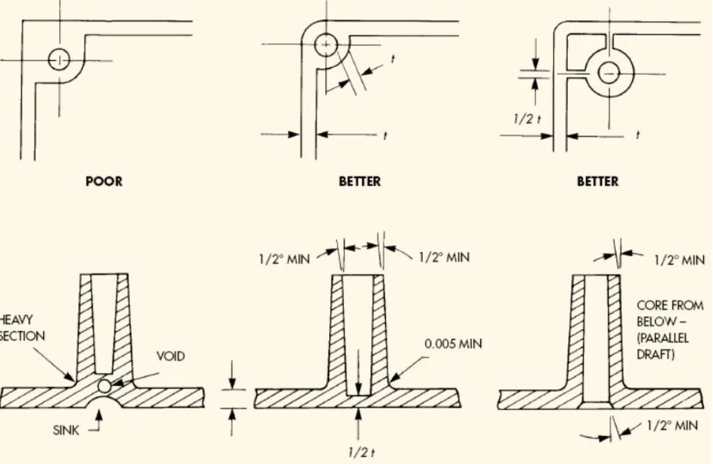
Ribs:
Ribs are integral features in plastic parts, designed to provide additional strength and stiffness. By reinforcing weak areas, ribs enhance the component's ability to withstand forces without significantly increasing weight or thickness, making the part more efficient and cost-effective. In assemblies, ribs can act as locators or arresting features, helping parts align during assembly, reducing the need for complex fasteners that might loosen over time. They can also serve as stops or guides in applications like automotive lighting systems, ensuring proper alignment and positioning.
The thickness should be optimized to avoid excessive material use while ensuring adequate reinforcement. The number of ribs should strike a balance, as too many can increase complexity and material usage, while too few may not provide sufficient strength. Rib height must be carefully managed to prevent warping during molding and ensure the part's functionality. Manufacturability is another key concern, as excessively tall or narrow ribs may lead to molding defects. Strategic placement of ribs in high-stress areas is essential for maximum benefit, such as on load-bearing surfaces. Overall, rib design requires careful optimization to balance strength, material use, and manufacturing constraints.
Dog House :
A dog house plays a crucial role in plastic part design, especially for assembly purposes and addressing potential plastic defects during manufacturing. It serves as a structural feature or attachment point within the mold, helping to guide the assembly process and ensure accurate alignment of parts. This enhances efficiency and reduces the risk of misalignment or damage during assembly, especially in high-precision applications like automotive or electronics. Additionally, in injection molding, a dog house helps prevent defects by ensuring proper gating, material flow, and ejection, reducing the risk of issues like flow marks or incomplete fill.
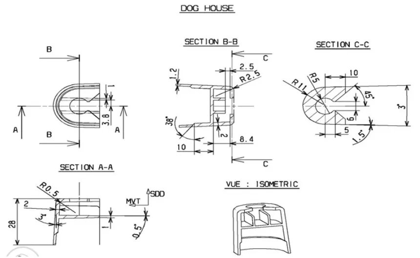
The design of a dog house varies based on the assembly process but typically includes features such as specific heights and locations for correct alignment, structural integrity to withstand assembly forces, and ease of use for quick attachment and removal. Compliance with engineering drawings is critical, ensuring dimensional accuracy and material selection that meet the part’s strength requirements. The dog house design must also integrate well with other features like ribs or flanges for overall functionality and strength.
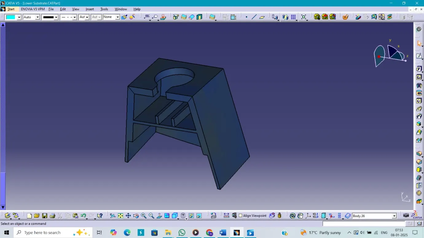
Various types of dog houses are used depending on the application, including round or square designs for fasteners or custom shapes for unique requirements. Common examples include their use in the automotive industry to position components like brackets and sensors, in consumer electronics for aligning circuit boards and connectors, and in medical devices where precise alignment is essential for safety and functionality.
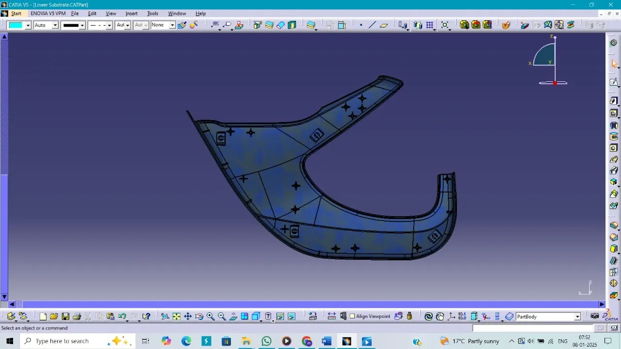
Push pins:
Push pins are versatile fasteners commonly used in plastic part design and assembly, offering a quick and effective way to secure components without the need for screws, bolts, or other traditional fastening methods. These fasteners are typically made from plastic or metal and are inserted into a corresponding hole in a part to temporarily or permanently hold it in place. Key features of push pins include a self-locking mechanism, simple insertion, and no need for specialized tools, making them ideal for fast, high-volume manufacturing processes across industries like automotive, electronics, consumer goods, and medical devices.
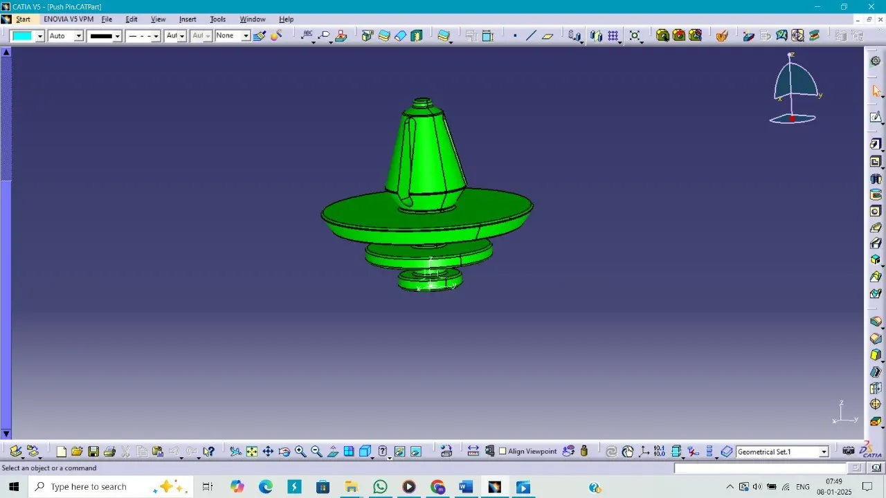
There are several types of push pins, including standard push pins, snap-fit push pins with flexible legs, spring-loaded push pins, and push rivets that expand upon insertion. These fasteners come in a variety of materials such as nylon, polyamide, polypropylene, or metal, and are available in different sizes and shapes to suit specific application needs.
Push pins offer multiple advantages, including ease of use, cost-effectiveness, and reusability. They simplify the assembly process by eliminating the need for tools, reduce labor and time costs, and can be reused in various applications, making them ideal for high-volume production. Their versatility allows them to be used in a range of industries, from automotive to consumer electronics and furniture manufacturing.
Flanges:
Flanges are essential components in plastic part design, providing a secure connection, support, and alignment for parts. They serve as attachment points for joining components, particularly in assemblies requiring fasteners. Flanges also offer sealing capabilities, commonly used in applications like piping, tanks, or enclosures, where they help ensure a leak-proof seal with the help of gaskets or O-rings. Additionally, flanges add rigidity to parts, helping distribute stress evenly, and they can guide parts into proper alignment during assembly.
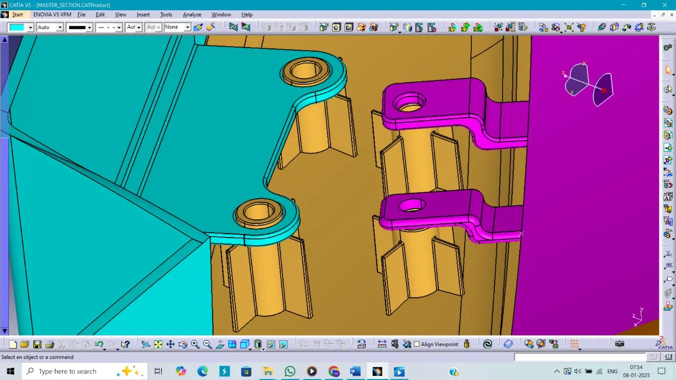
The design of flanges involves considerations such as shape, size, and thickness. Flanges come in various shapes like flat, raised, or threaded, with dimensions determined by the application, load requirements, and compatibility with other parts. The flange thickness is crucial for strength, while mounting holes are typically included to secure the flange with fasteners. Raised flanges are ideal for sealing or alignment, whereas flat flanges are used in low-pressure environments or when a seal is not needed.
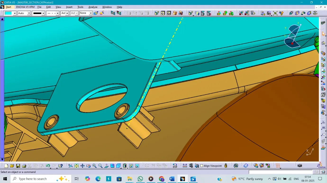
There are different types of flanges, including those for mounting or assembly, sealing, threaded connections, and weld neck flanges, each suited for specific applications. In plastic components, flanges play an important role in connecting parts in complex assemblies, enhancing strength, rigidity, and ease of manufacturing. They can also improve aesthetics while providing functional benefits like strength and attachment ease. In the automotive industry, for example, flanges are used to connect plastic and metal parts or attach components to frames.
 \
\
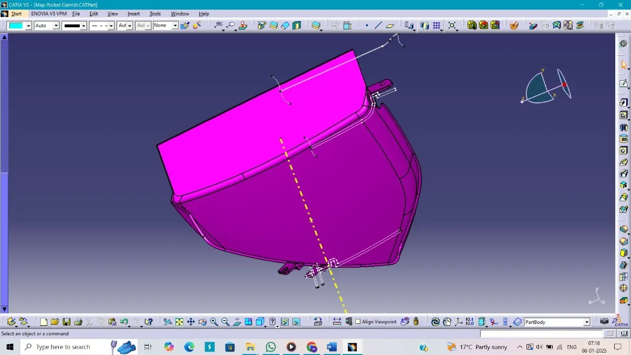
Tolerance and Fit: The flange design must account for manufacturing tolerances to ensure a proper fit with other parts or fasteners. Misalignment can lead to assembly issues or weaken the joint.
Stress Distribution: The flange should be designed to evenly distribute stresses across the part, preventing weak spots or deformation under load.
Space and Design Constraints: The flange design should consider available space and other structural features, ensuring it does not interfere with other components or compromise the overall functionality of the assembly.
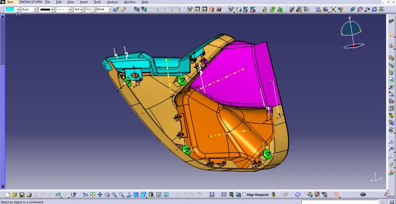
Rendering in CATIA V5
To render a component in CATIA V5, follow these steps:
- Apply Material: Click "Apply Material" in the Render or Materials toolbar, then choose a material from the library or create a custom one.
- Select the Part: In the Part/Assembly Tree, click the component you want to apply the material to.
- Apply and Confirm: Click "Apply Material" to assign it, then click "Ok" to lock it in place.
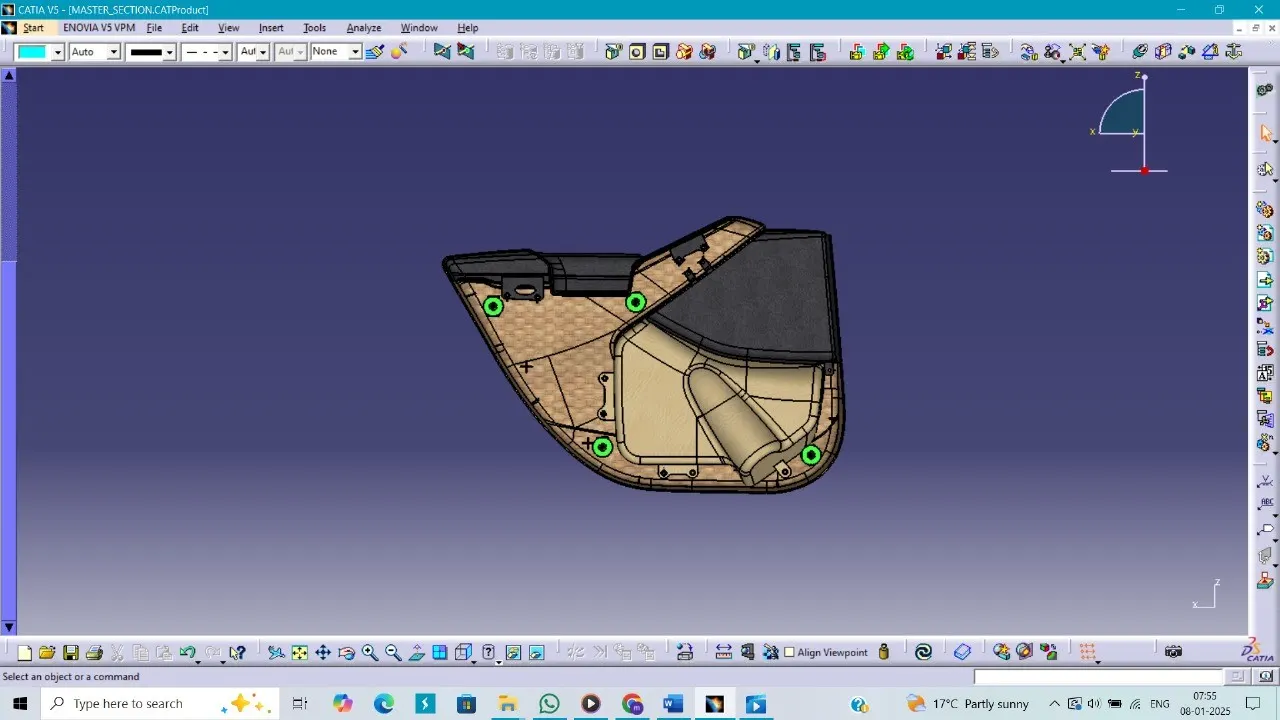
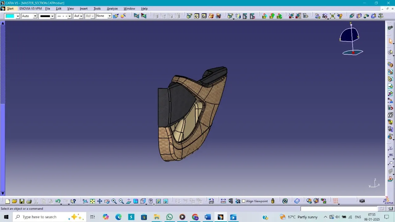
Apply and Confirm: Click "Apply Material" to assign it, then click "Ok" to lock it in place.
Set Up the Environment: Click the "Render" icon and adjust settings such as lighting, camera angle, reflection, transparency, and background to enhance the model’s appearance.
Preview and Adjust: Preview the render, and adjust material, lighting, or camera settings as needed.
Save the Image: Once satisfied, click "Save" to store the rendered image in your preferred format (JPEG, PNG, etc.).