Week 12- Final project
Final Project
Aim :-
- To develop a Door Trim panel CAD model by considering the inputs given (ie., Class A surfaces,Master Sections) as like in OEM and Tier 1companies.
- Develop an attachment strategy for the complete Door Panel work by creating the B side features as per dedign guidelines.
- Use Pushpin (given) with Dog House for attaching the Trim with the BiW part and Heat Stakes for part to part attachment.
Methodology :-
Creation of Lower Substrate :-
- Top-Down approach of Assembly is followed for developing the Door Trim panel.
- DFMA (Design for Manufacturing and Assembly) are main criterias should be kept in mind.
- Five Part Files are segregated inside one Product File starting with the Master Sections file and then proceeding on with the other Class A surface files given.
- Now,starting with the surface quality inspection of the given Class A of the Lower Substrate,which comes out fine.
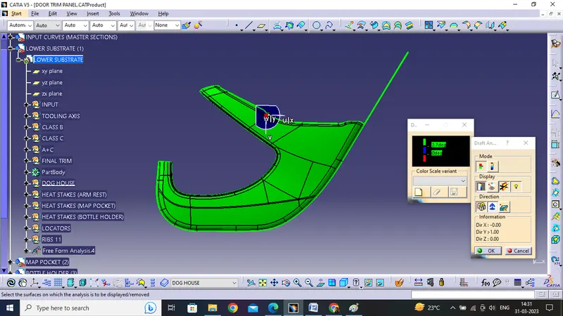
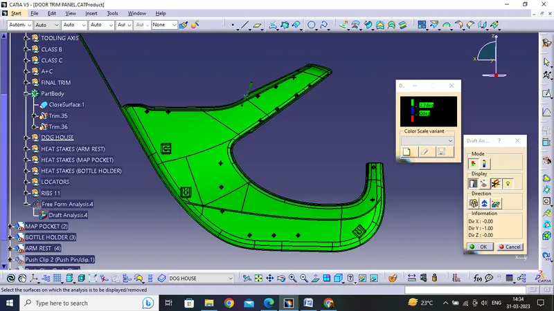
- Creating the Tooling Axis for the Lower Substrate using Point-Direction option of the Line creation by checking the compass direction,and then checking the Tooling feasilbilty by performing Draft Analysis.
- And finally creating the Solid Body out of the Class A given,by offsetting the Class A to 2.5 mm (part thickness given in the Master Section) to form Class B.
- Forming Class C surface by using the Reference to Surface method and the by using the 3 deg Draft Direction.
Door Arm Rest :-
- In this case,first we need to improve the Class A,which is we’re not authorized to do in the Industries,rather it’s a Class A Stylist’s job for creating and doing any modifications to the Class A.
- Class A (given) :-
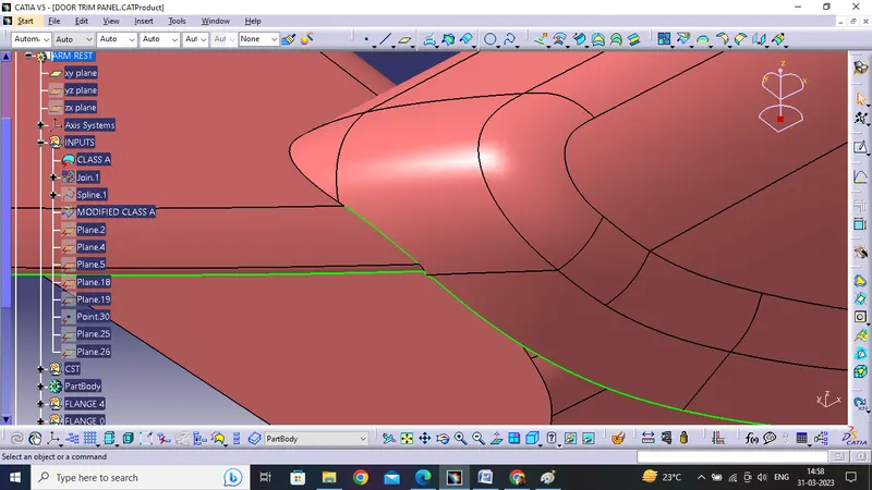
- Class A (improved) :-
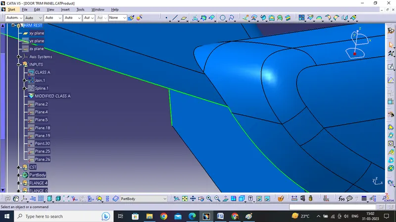
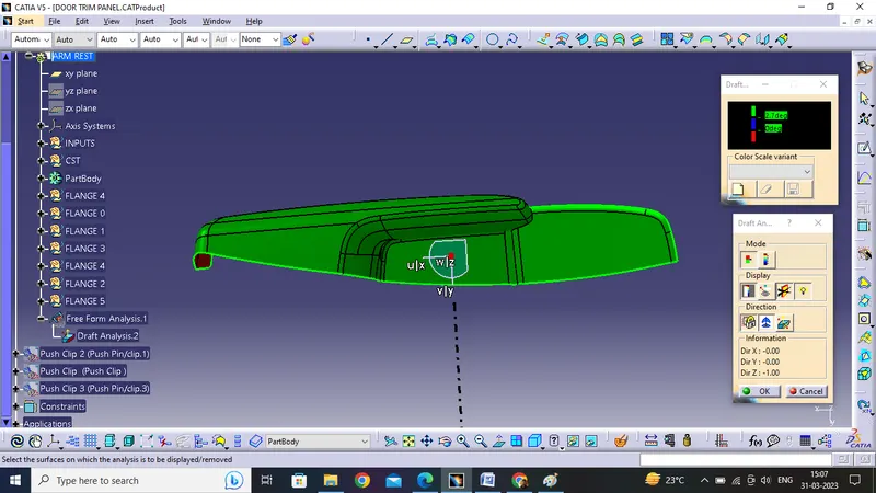
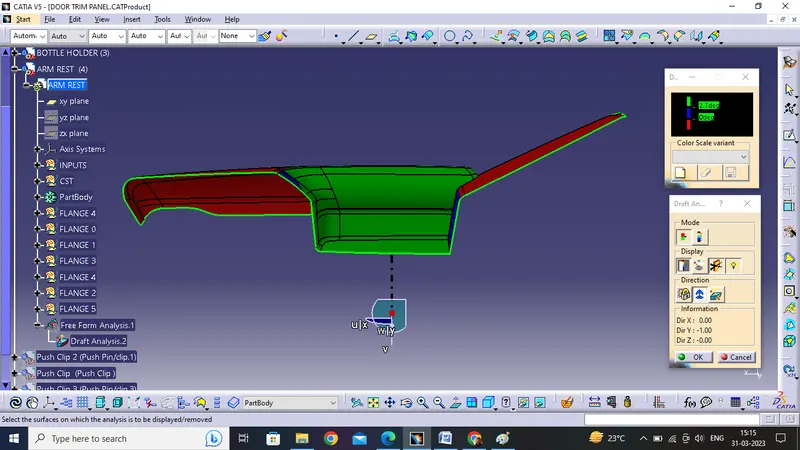
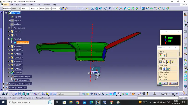
- In this case we won’t be able to clear all the faces in the Main Tooling and we require a Side Tooling as well.
- Draft Analysis (Main Tooling) :-
- Draft Analysis (Side Tooling) :-
- After checking the tooling feasibility we proceeded with the Class B & C surface creation and finally generating a Solid Body out of it.
- Draft Analysis on the Solid Body (Main Tooling Axis) :-
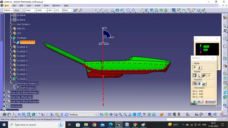
- Draft Analysis (Side Tooling Axis) :-
Map Pocket :-
- Upon doing the surface quality check and then the draft analysis,we found out that there aren’t any open boundaries and all the faces will get cleared in the Main Tooling Axis itself.
- Draft Analysis on Class A :-
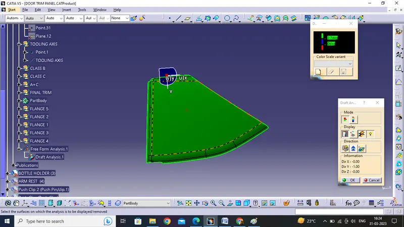
Draft Analysis (Solid Body) :-
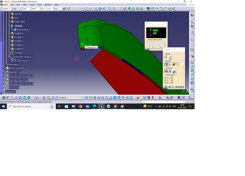
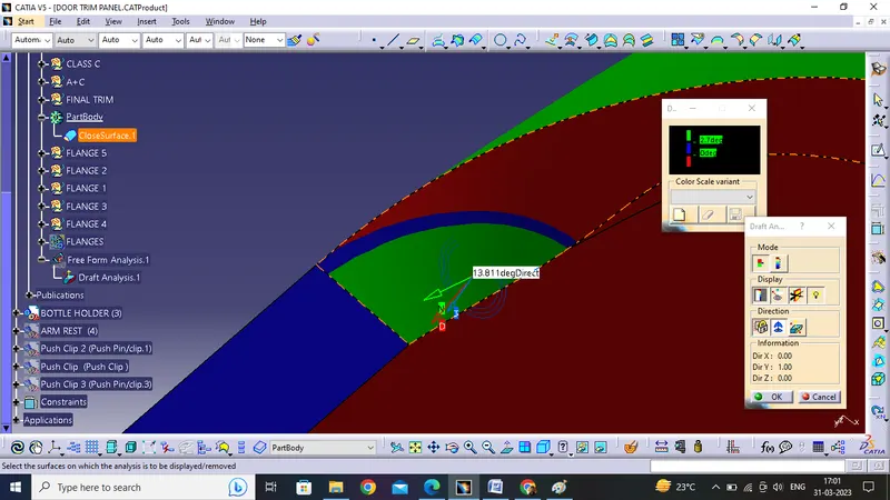
- Due to improper Class A surfaces,majority of the Class C aren’t getting cleared in the Main Tooling Axis and for that we need to inform the Stylist for Class A modifications.
- Few surfaces are clearing the Main Tooling and the regions are shown below.
Bottle Holder :-
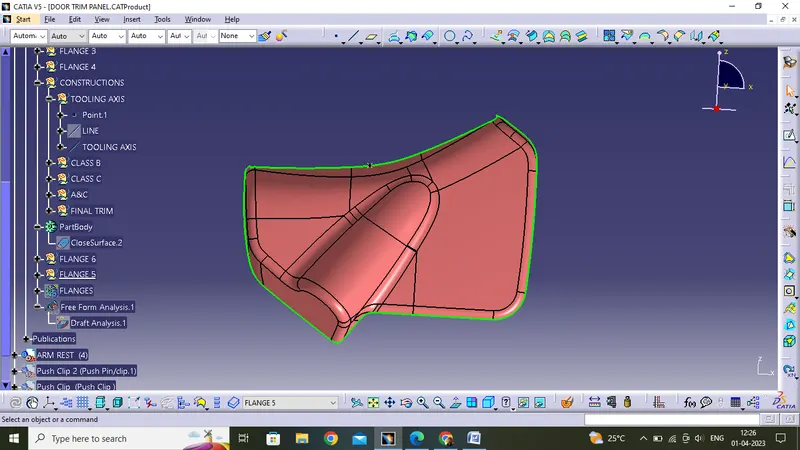
- Upon performing the Draft Analysis on Class A,we found out that few faces aren’t clearing minimum required draft of 3 degrees,and for that we need to inform the Class A Stylist for improvements.
- Draft Analysis Image :-
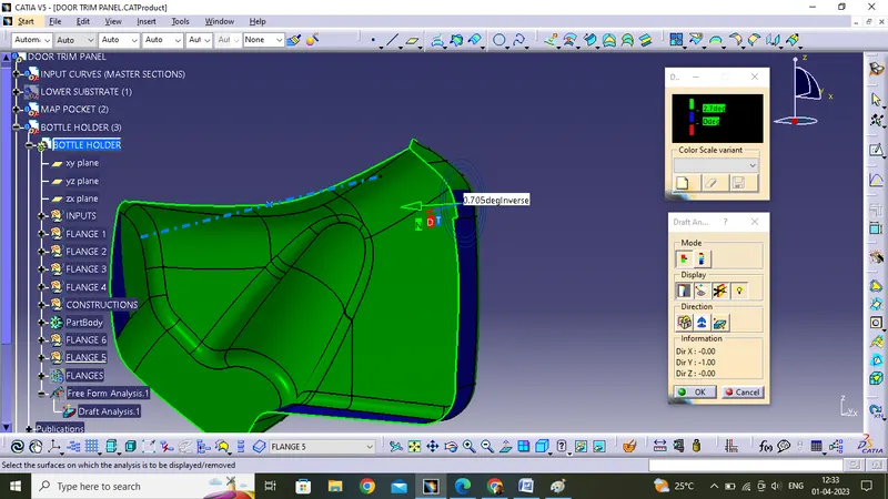
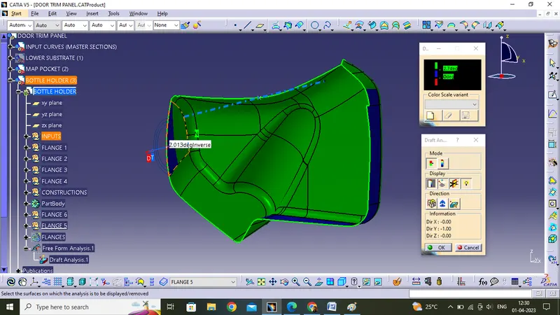
Draft Analysis on Solid Body :-
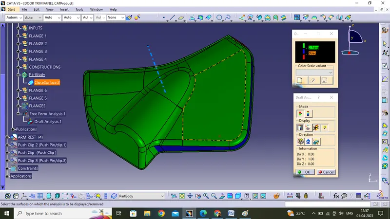
- Upon performing the Draft Analysis on Solid Body,we found out that the almost all the Class A and Class C faces are cleared in the Main Tooling itself except for the few Class A surfaces for which modifications are needed.
Attachment Strategy :-
- 3-2-1 Principle will be followed for attaching the components amongst one another.
- For attaching the individual components created above with each other and also with the Sheet Metal/Biw Panel to form an entire single Door Trim Panel we need to design the attachment features onto the part.
- Here we’ll be using two types of attachment stratergies,one for Part to Part attachment and another for Trim to Biw attachment.
- Part to Part Attachment :- For attaching parts with one another,we’ll be using Heat Stakes and Locators (on Lower Substrate) with Flanges (onto the Arn Rest,Map Pocket and Bottle Holder).
- Part to Sheet Metal/BiW Attachment :- For this attachment,we’ll be using Push Clips positioned over Dog Houses (been made onto the Lower Substrate) so that the Lower Substrate Trim get proper alignment and positioning with the Sheet Metal.
B Side/Engineering features creation :-
Creation of Heat Stakes :-
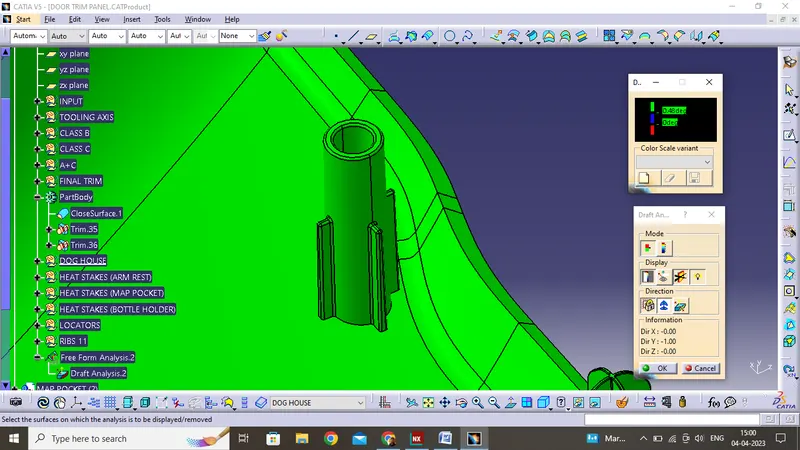
- The basic purpose behind the creation of Heat Stakes is for arresting the degree of freedom of the assembly along the tooling axis direction.
- Heat stakes are designed by referring the Master Sections given and by following the Tooling Axis direction of the Lower Substrate.
- Supporting Ribs are provided on the Heat Stakes for strengthening them
- The distance kept between Heat Stakes are 50-60 mm so that the hot plate doesn’t get in contact with another heat stake when plastic welding is being carried out.
- Heat Stakes (child) and Flanges (parent) are plastic welded by melting the protruding heat stake onto the flange.
- Height of the heat stake = 25 mm (by referring the Master Sections).
- Thickness = 3 mm
- Inner and Outer Dia = 4mm and 7 mm (by Master Section).
- Length of supporting ribs = 15 mm
- Thickness of ribs = 1 mm (40 % of the component’s thickness)
- Draft (heat stakes and ribs) = 0.5 deg (with the Component’s/Main Tooling Axis)
- Tip thickness ≥ 0.75 mm
All the Ribs design rules are followed.
Creation of Locators :-
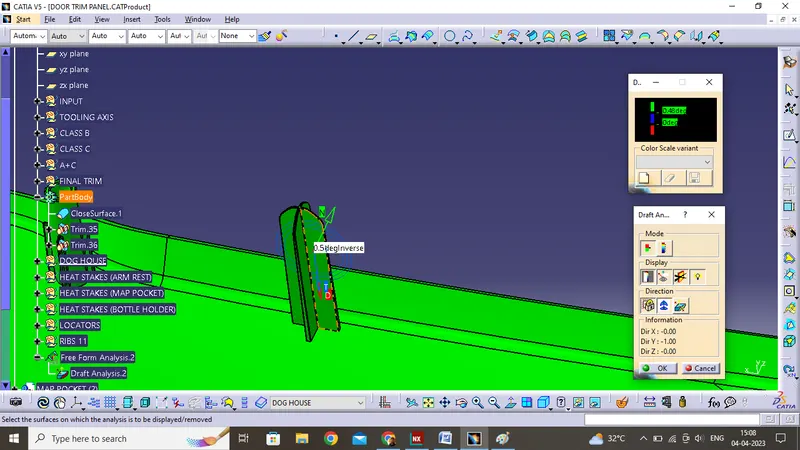
- 4-way locators are designed in order to arrest the remaining five degrees of freedom of the assembly parts.
- All the Rib design rules are followed while deigning the locators except the height criteria.
- The height of the locators are kept 5-6 mm more than that of the heat stakes,because first the positioning and alignment of the parts onto the Lower Substrate occurs and after that joining is done.
- Position of locators on the Lower Substrate is done in way that its adjoining parts gets properly positioned from both the ends.
Creation of Dog House :-
- Draft Analysis (Main Tooling) :-
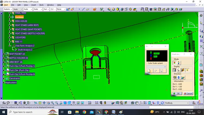
- Draft Analysis (Lifter Axis) :-
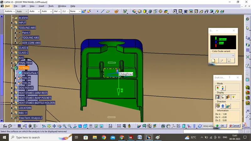
- Dog House is created on the Lower Substrate for placing the Push pin over it,thus,attaching the Lower Substrate with the Door Panel.
- Coring/Sink Saver is provided at the bottom of each Dog House for avoiding the Sink Marks on the A side.
- The wall thickness at the contacting surface after Coring out must be kept 40 % or less than the Main Wall Thickness of the component.
- Height of coring is kept between 3-6 mm from the Class B surface.
- Dog Houses are kept at a distance of 85-90 mm from any other attachment features so that the Lifters can move easily for clearing the internal undercut of the Dog House.
- Width of dog House is kept at a minimum of 12 mm.
- Draft of 0.5 degrees is given along the Main Tooling for the outer parallel faces along with 0.5 degrees draft for the inner faces as well along the Lifter Axis.
Flange Creation :-
Arm Rest :-
- Draft Analysis :-
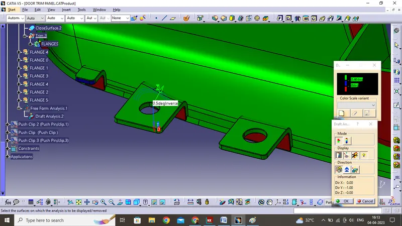
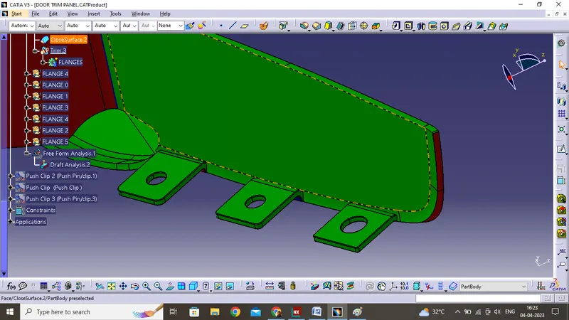
- Minimum draft of 0.5 degrees is given wrt Side Tooling of the Arm Rest.
- Fillets are given as per the Master Section provided by neglecting the leatherette cover thickness.
- Minimum fillet of 0.25 mm are given at rest of the areas.
Map Pocket :-
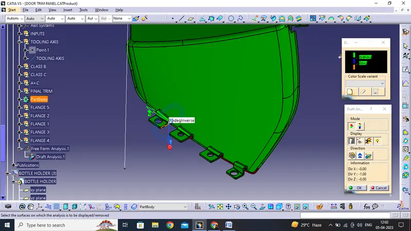
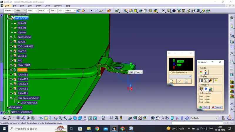
- At the below shown single flange,due to presence of uneven edges,it wasn’t possible to give proper flange values at the back part.So,given minimum fillets possible.
Bottle Holder :-
Draft Analysis :-
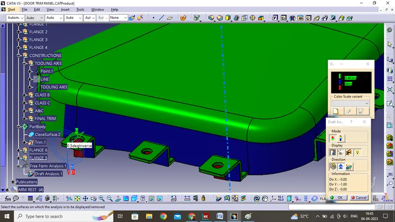
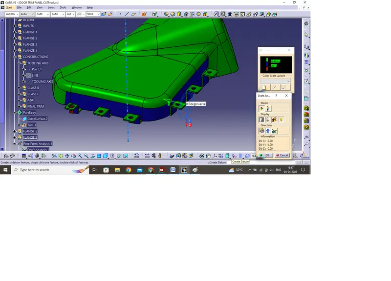
- Draft analysis for the Flanges are carried out along the Main Tooling of the Door Arm Rest by providing 0.5 deg draft.
Final Assembly :-
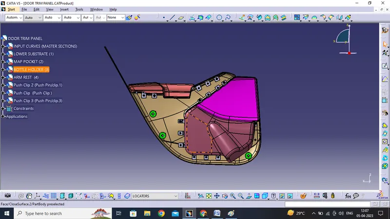
- The below image shows the entire assembly of the Door Trim Panel complete work after attaching the Push Pins given.