Week 12- Final project
Data Recieved :
Class A Surface or Styling Surface is recieved as Arm Rest , Map pocket , bottle Holder & Lower Substrate . With this data New product is to be developed.
ARM REST
1. CLASS A SURFACE :
Given Class A is Checked for improvement .
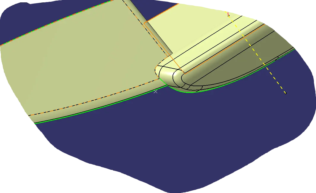 The given Class A surface is not good , so we have to improve it.
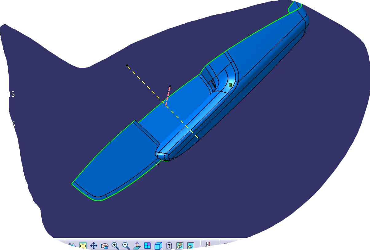 → This is Improved Class A Surface.
2.Creation Of Tooling Axis
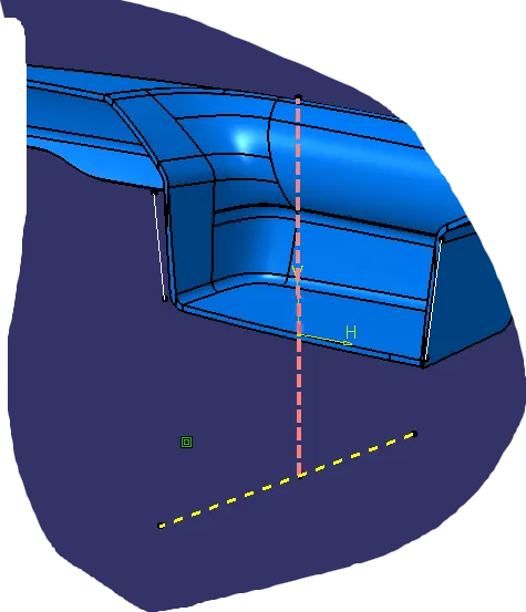
Checked for Suitable Direction for tooling And Using Bisecting Method Tooling Axis is Created .
3.Draft Analysis Of Class A Surface :
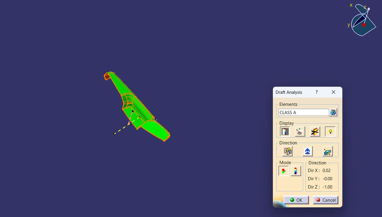 All areas are clearing 3 Deg Draft execept some areas further to be mentioned.
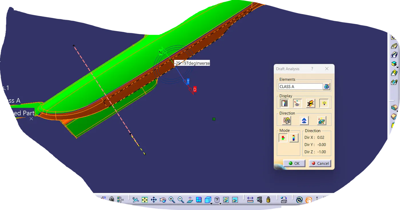 -25 deg Draft is shown in areas this need to be informed to class A Team.
4.Creation of Class B Surface :
Class B surface is created by offseting class A surafce by 2.5 mm as per the mastersection. After offseting some area not get offseted , there patches formed. This patches are closed by surface creation features.
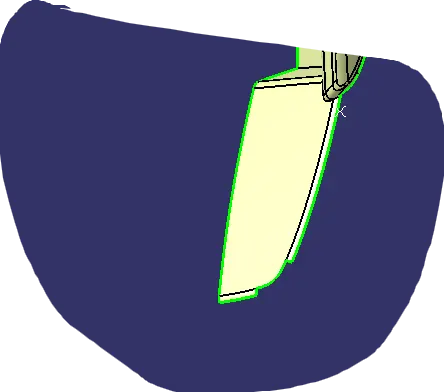
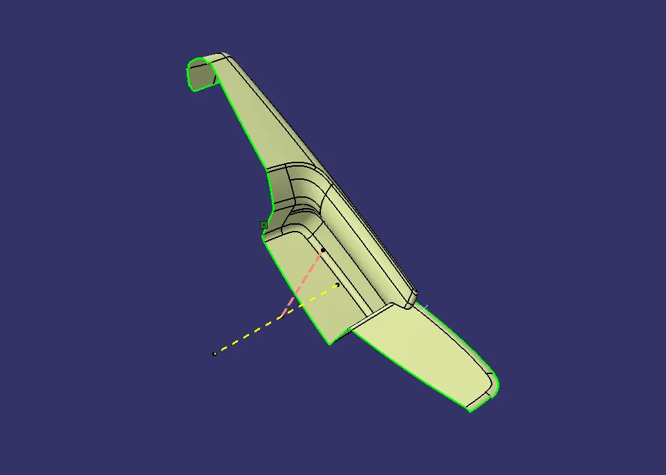 → Corrected Surface.
5.Creation of Class C Surface :
Class C Surface Acts as connector between Class A and B Surface .
Boundary of Class A Surface is Sweeped to 3 deg and as it connects with b surface Both are trimmed.
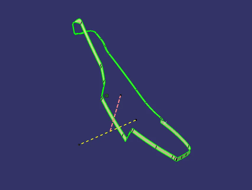
6.Creation Of Closed Surface :
Class A joined with C surface And it is trimed with B surface to get a closed surface.
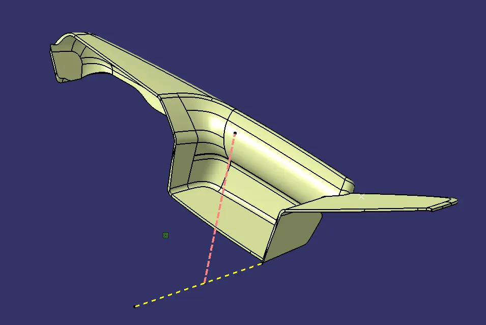
7. CLosed Solid Arm Rest Body :
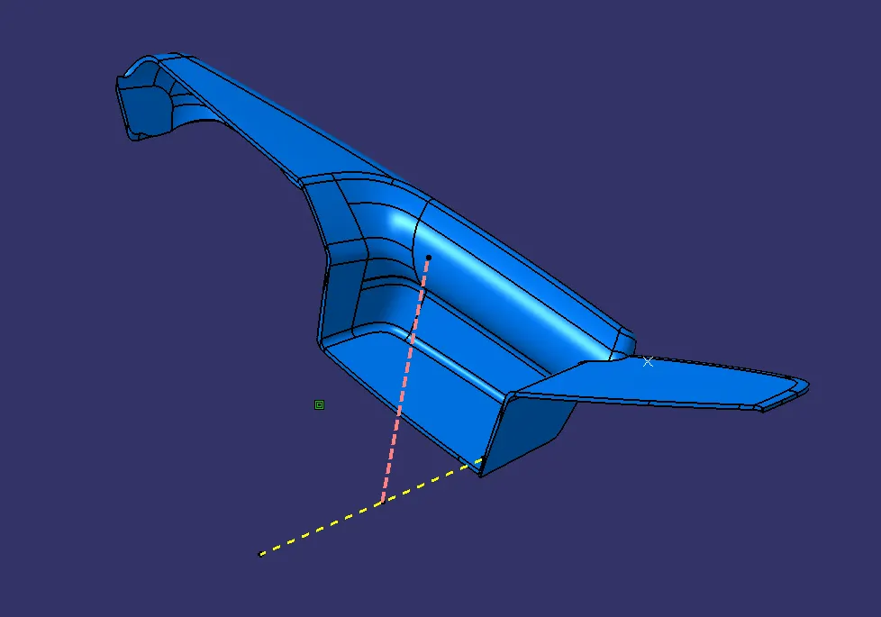
8. Creation Of Flanges :
With Reference to master section Flanges are Created for connecting it to lower substrate.
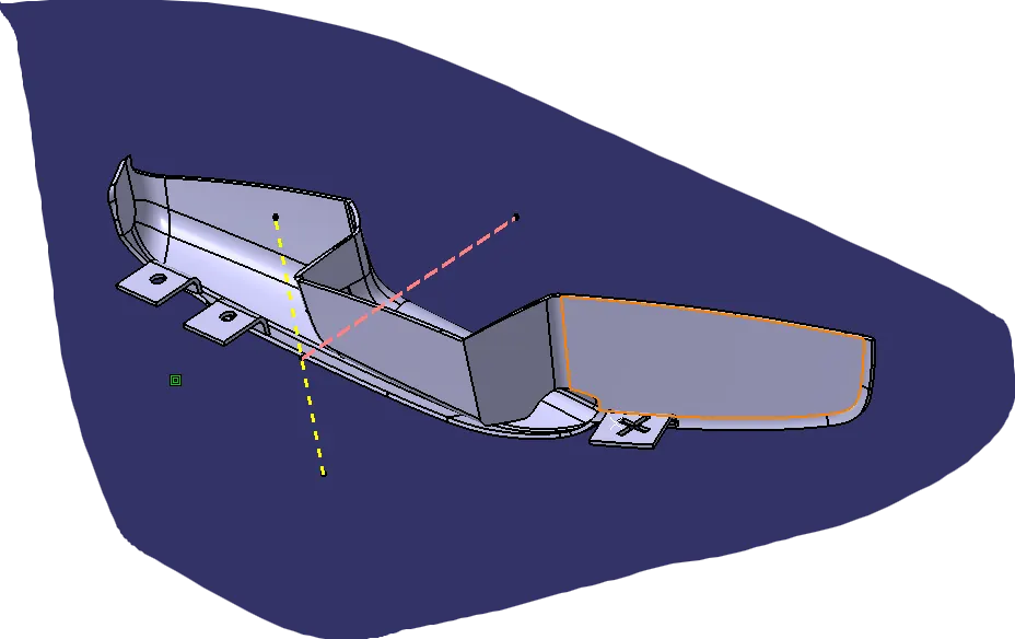
9. Draft Analysis of Final Part :
NEED FOR DRAFT :
Draft is given in the direction of tooling axis of core cavity opening'
it is given for easy ejection of part from thr mold without friction.
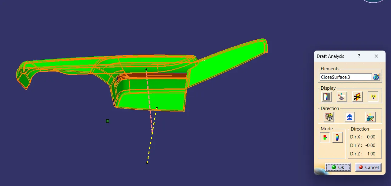 All Areas Are cleared except some areas with negative draft , that need to be corrected by class A team.
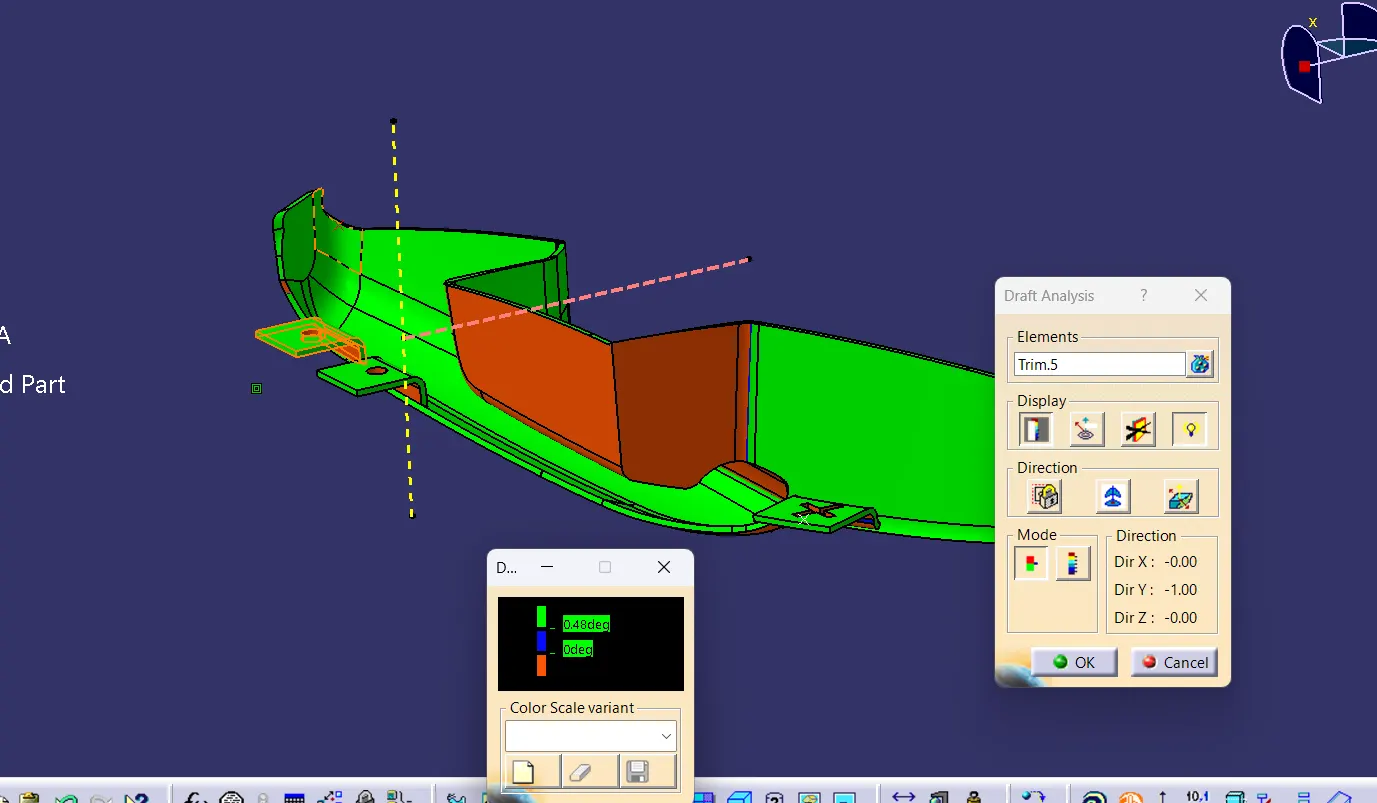 → Flanges All Cleared Draft of 0.5 deg.
MAP POCKET
1. CLASS A SURFACE :
Check given class A.

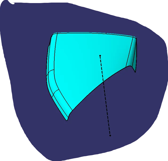
2. TOOLING AXIS :
Create Tooling Axis by checking suitable tooling direction .
3. Draft Analysis of Class A :
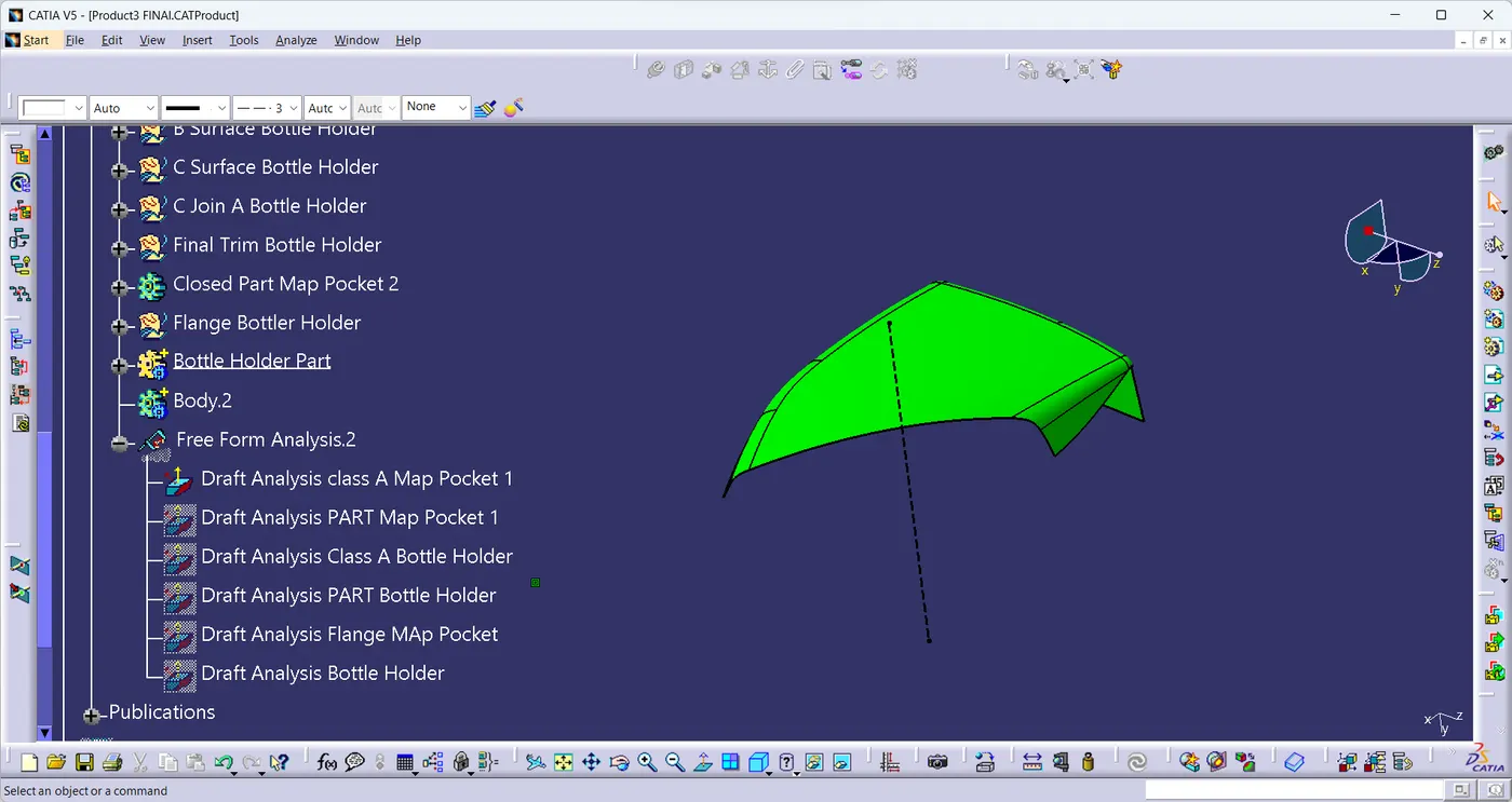
3 Deg Draft is cleared on all surface.
4. CLASS B :
As Per Master section Class A Surface is Offseted to 2.5 mm and the patches found are cleared using surface operations.
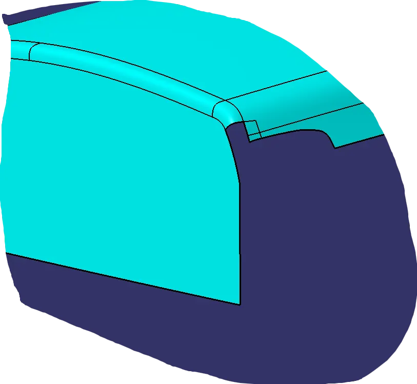 → Patches.
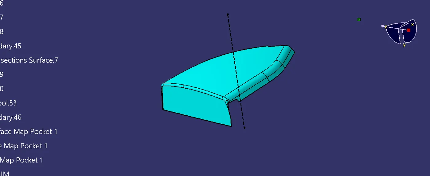
5. Class C Surface :
By Connecting Class A and Class B Surface Class C Surface is created in between that using sweep operation with ref 3 deg.
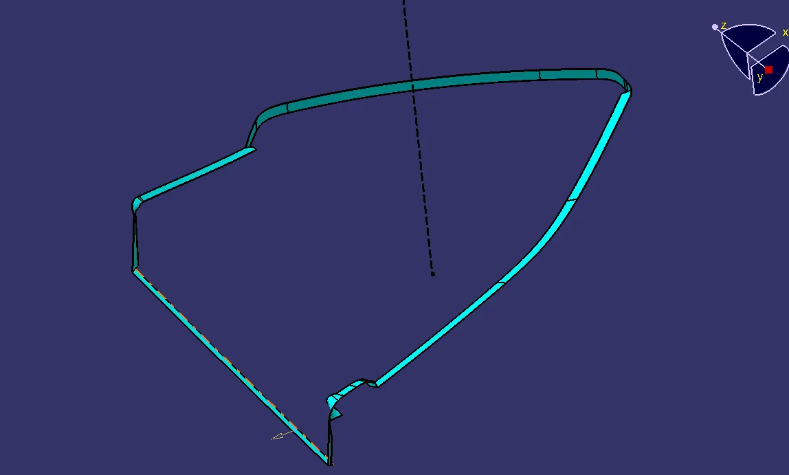
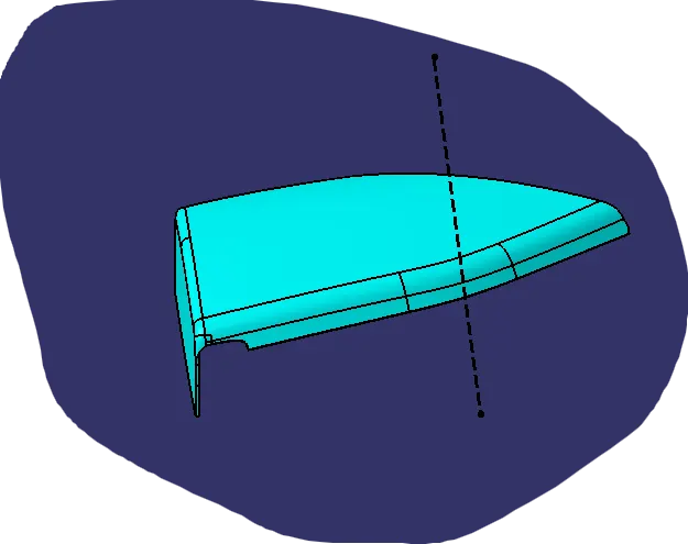
6. CLosed Surface :
By trimming All 3 Surfaces closed Surface is formed.
7. FLANGES :
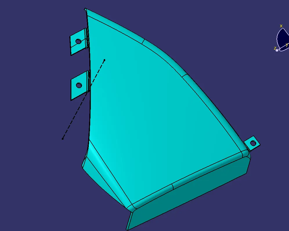 BY Considering Master section Flanges are created here for connecting it with Lower Substrate.
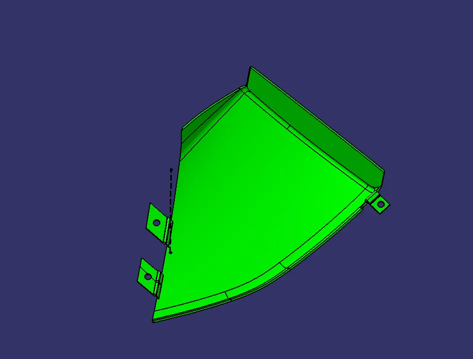
8. Draft Analysis Final Part :
All Areas Are found to have minimum draft of 3 deg and found to be manufacturable.
BOTTLE HOLDER
1. CLASS A :
Check Class A Surface for quality.
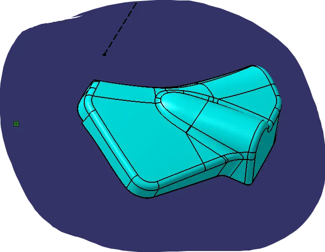
2. Tooling AXIS:
Tooling Axis is created According to suitable tooling direction.
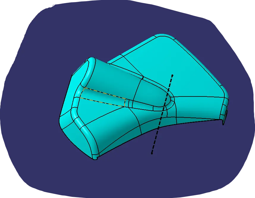
3. Draft Analysis of Class A Surface :
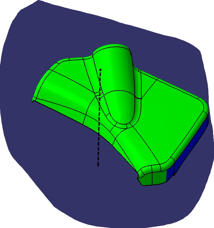 →All Surface Have Minimum draft of 3 deg except the areas in blue which have min draft of negative value , need to inform class A Team.
4. CLASS B SURFACE :
Created by offsetting it to 2.5 mm
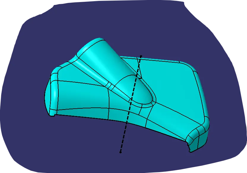
5. CLASS C SURFACE :
C surface created usign sweep operation.
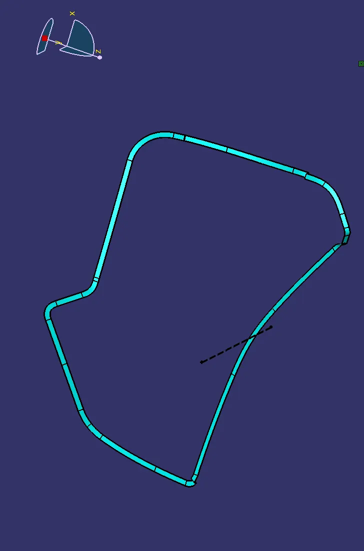
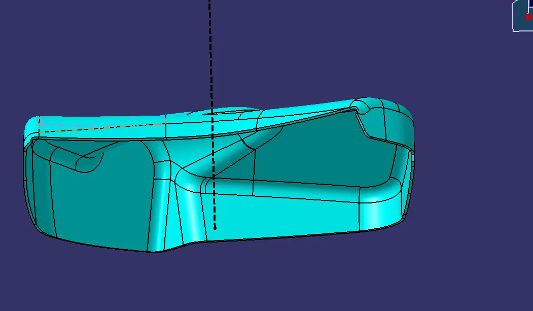
6. Final PART :
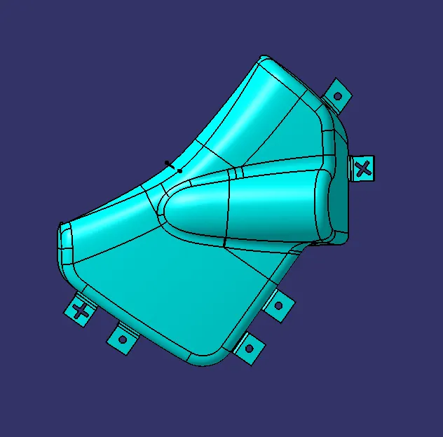
7. Flange Creation :

8. Draft Analysis on Bottle Holder :
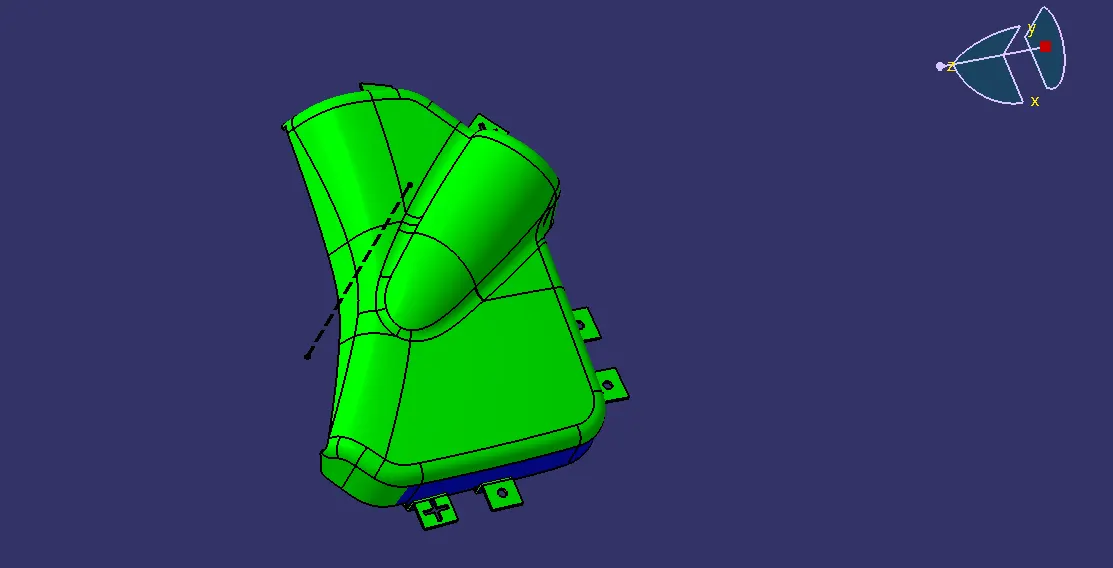
It seems that all areas are clearing draft execept some blue areas which need to be corrected by styling team.
LOWER SUBSTRATE
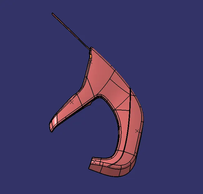
1. CLASS A :
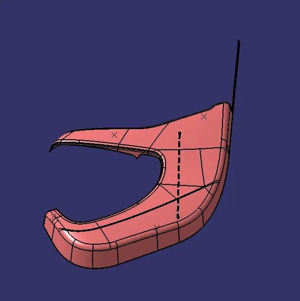
2. Tooling Axis :
3. DRAFT ANALYSIS of CLASS A :
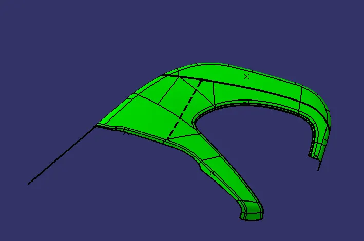 Class A is found Good with clearing 3 deg draft. And ready for Further Process.
4. CLASS B :
Offseted 2.5 mm by refering master section.
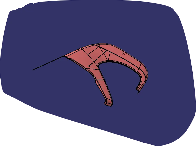
5. CLASS C :
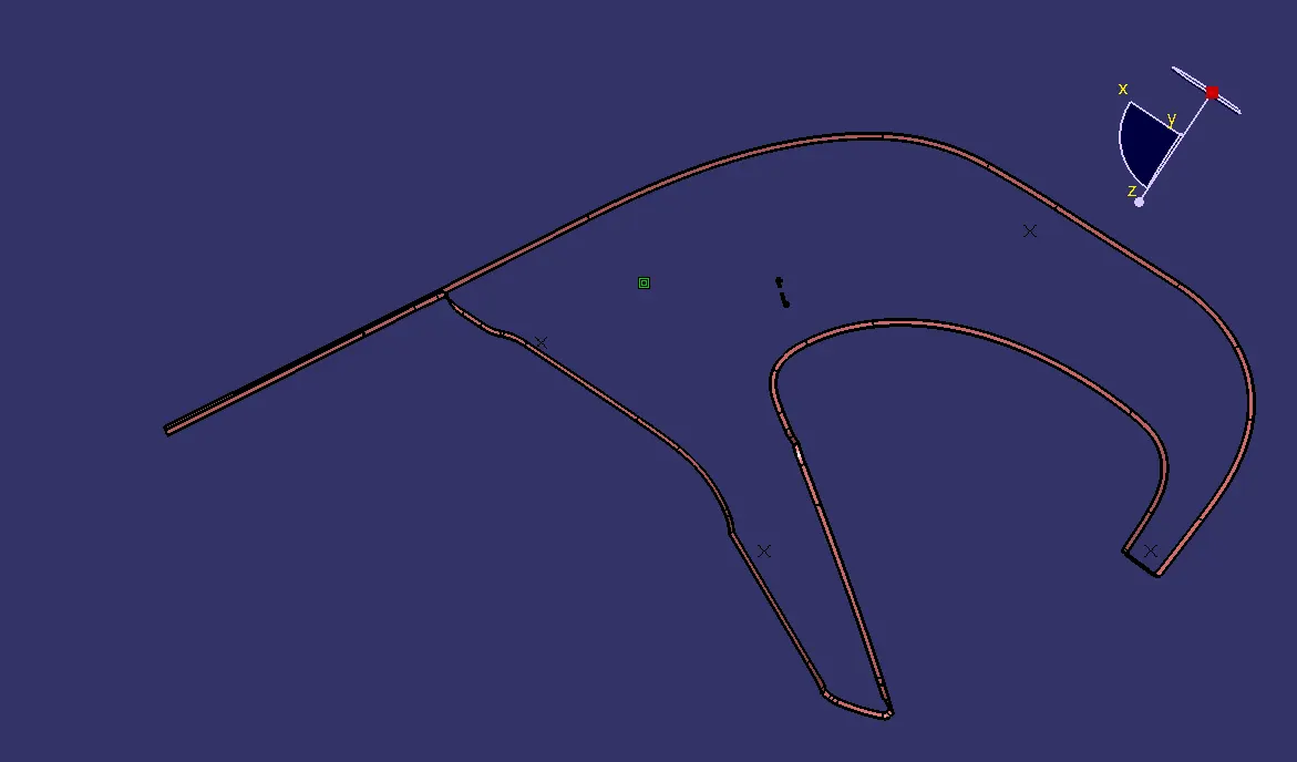
6. Final SOID PART :
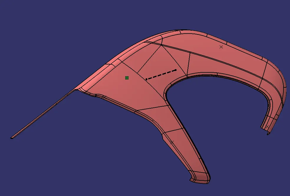
7.Draft Analysis on Solid Body :
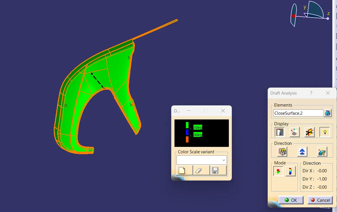
All Area have Minimum Draft of 3 degrees.
HEAT STAKES
HEAT STAKES CREATION :
- Heat stakes are used to assemble two parts together by heating and cooling the plastic and further becomes the joint.
- Here we used 9 Heat stakes .
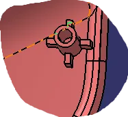
DRAFT ANALYSIS OF HEAT STAKES :
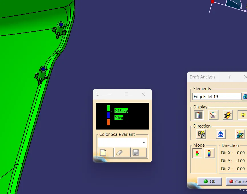
ALL FACES HAVE MINIMUM DRAFT OF 0.5 DEG...
LOCATORS
LOCATORS CREATION :
- Locators serves the purpose of proper locking of two components. and arrest degrees of freedom
- There are two types , 2 way loacators & 4 way locators.
- Here we have used 3 Four way Loacators.
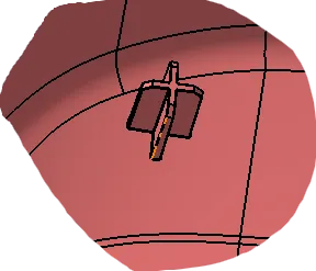
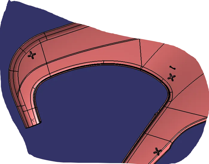
Draft Analysis of four way Locators :
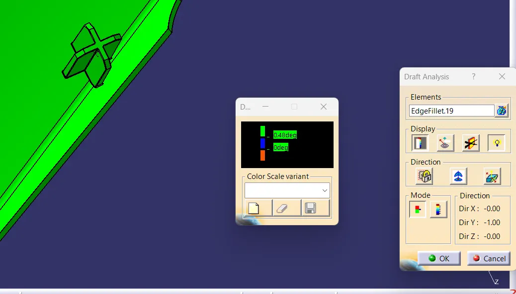
ALL FACES HAVE MINIMUM DRAFT OF 0.5 DEG ...
DOG HOUSE
CREATION OF DOG HOUSE :
- The Purpose of DOG HOUSE is to Avoid sink marks in B Surface Area with less Cross Sectional Wall.
- And to mount any Engineering Features in it.
- Here 3 Dog Houses are created with a slot on top were Push Clips with Locators are allinged.
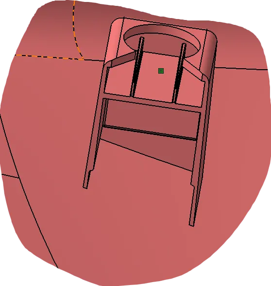
DRAFT ANALYSIS OF DOG HOUSE OUTER SURFACE :
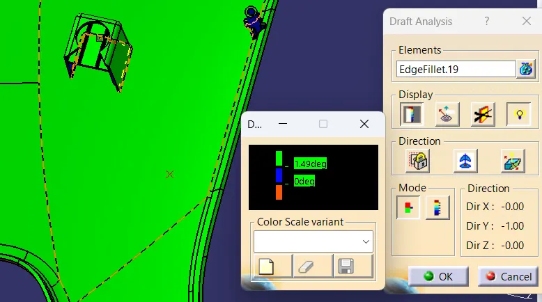
Draft Analysis of Dog House Inner Surface :
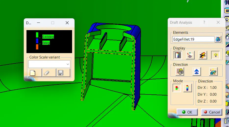
ENGINEERING FEATURES :
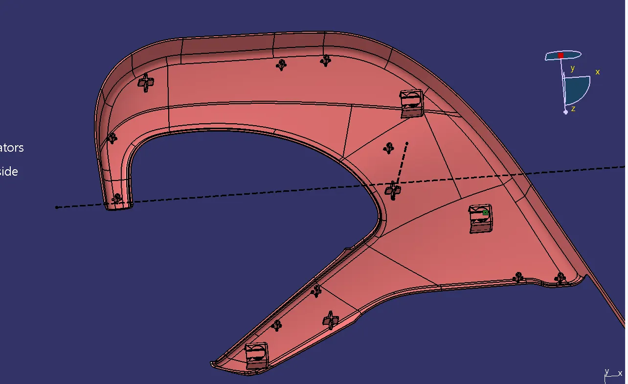
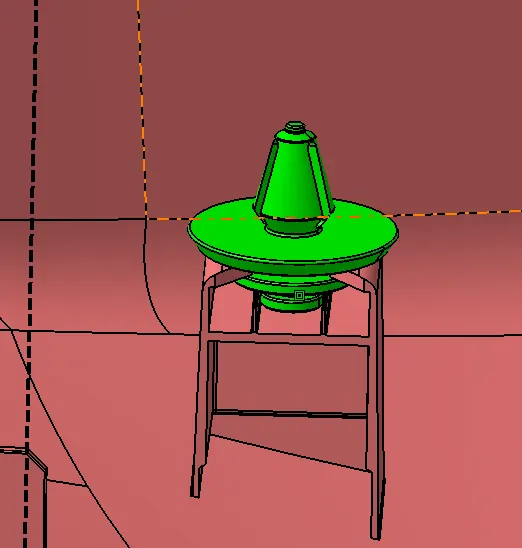
PUSH PIN:
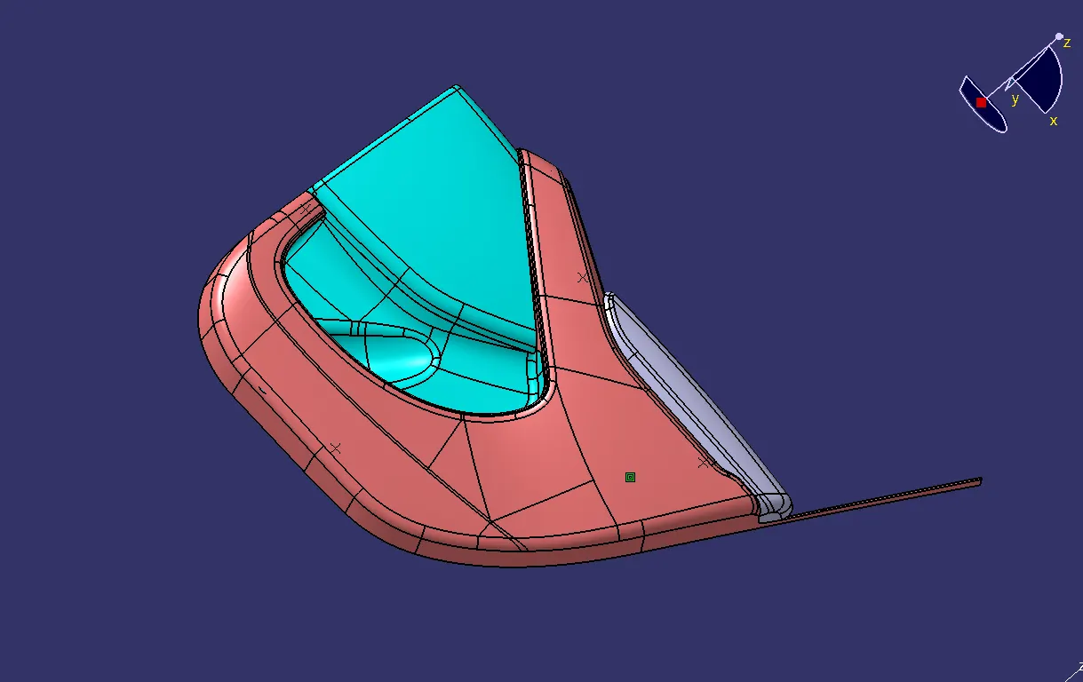
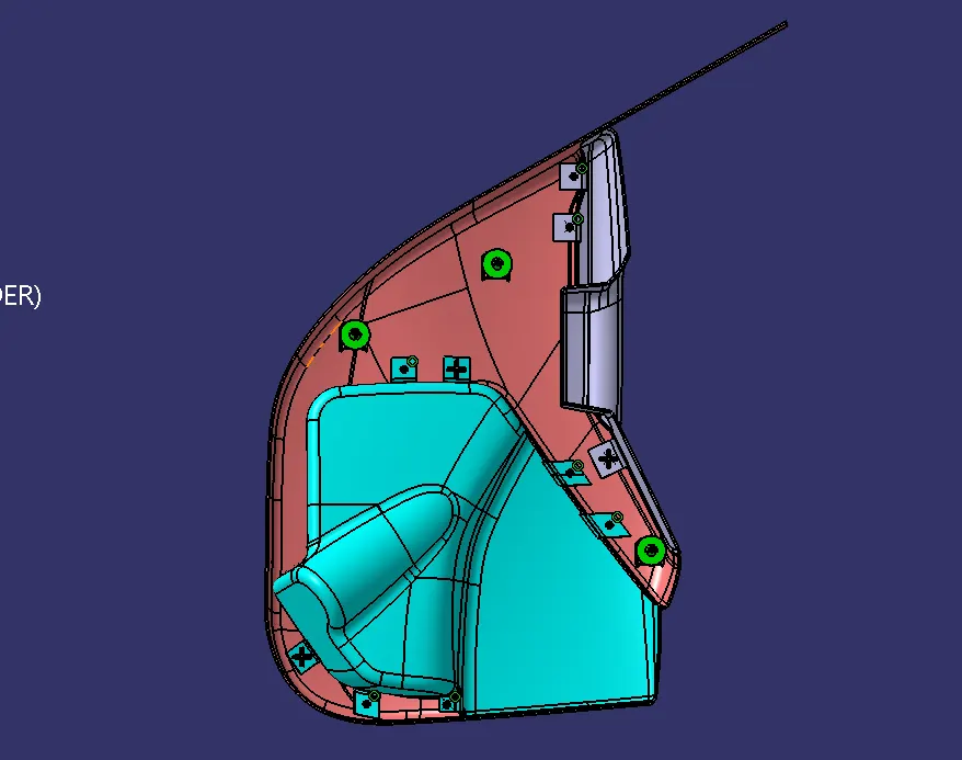
FINAL ASSEMBLY :
Thank you...