Week 12- Final project
Door Panel – Final Project
Aim:
To create the Door inner panel with the given class A surface along with the master section and add the necessary engineering feature which needs to fix the component.
What is Door Panel?
Door panels serve as an interface between the interior of the car and the inner workings of the door, and between vehicle occupants and the door. They are expected to meet a variety of design specifications regarding safety, aesthetics, and functionality. In addition, they are expected to continue the material theme of the dashboard and pillars while concealing intricate electrical and mechanical components for operating locks, windows, and other features. The door panel has evolved from a simple two-part system of latch and simple winding mechanism to a more sophisticated enclosure. Doors currently have an inner full-width panel consisting of electronic windows, central locking system, and speakers. These panels typically consist of a foamed core covered with either textiles or plastics.
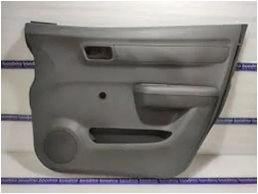
Procedure for creating door panel:
Steps involved in creation of Door Panel
- Analyze the Class A surface
- Tooling Axis Creation
- Draft analysis (Class A)
- B-Surface Creation
- C-Surface Creation
- A+C Surface Creation
- Final Trim (Closed Part)
- Surface to Solid Body Conversion
- Engineering Feature Creation
- Flange creation
- Heat Stake Creation
- Dog House Creation
- Locator Creation
- Final Draft analysis ( Solid Body with engineering features)
- Assemble the pushpin and all other commodity.
Workbench used:
- Part Workbench
- Generative shape design (Surface Workbench)
- Assembly Workbench
Analyze the Class A surface:
The first condition before entering into the design step is analyzing the given class A surface.
Whether the given surface is a single commodity or not and also check the draft analyze.
In CATIA software we have two options to check whether the given surface is single surface or not.
- Join Command
- Boundary command
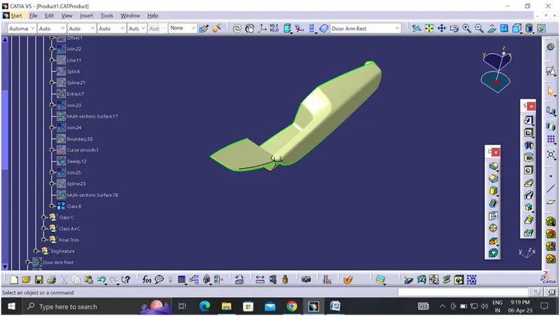
Arm Rest:
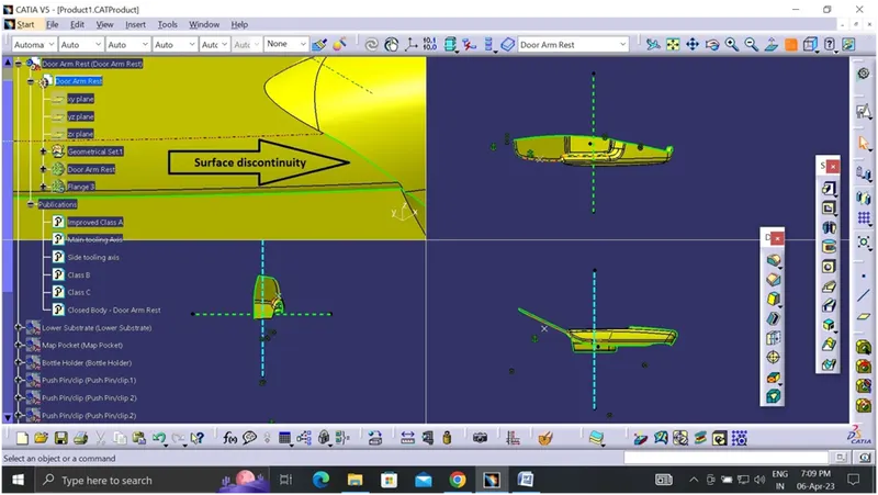
In first image clearly visible the given class A surface has some surface discontinuity. In this case it happened in real life scenario; ask the class A engineer to rectify the issue. But now in this case we have to rework on the Class A surface and needs to improve them.
For that use the Join command and select the class A surface and make the tolerance value as 0.1mm.
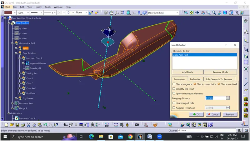
Now we have improved class A surface. In future we have to create B & C surface based on Improved Class A Surface only.
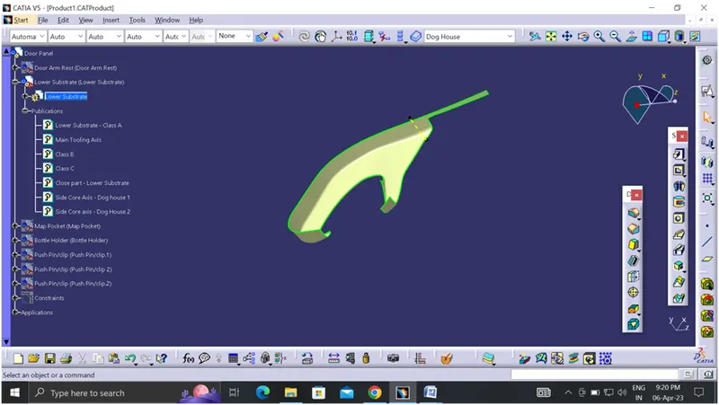
Lower Substrate:
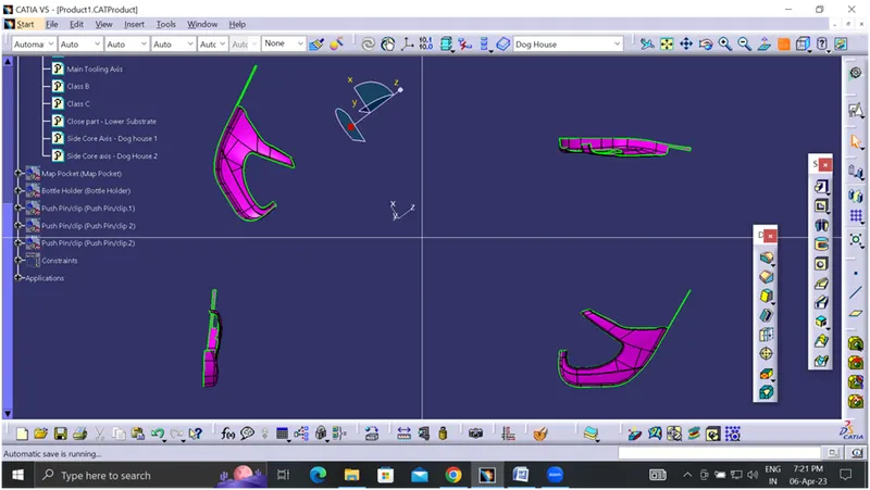
Found no Surface discontinuity.
Map Pocket:
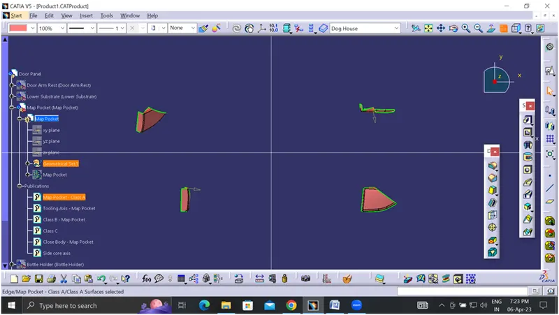
Found no surface discontinuity
Bottle holder:
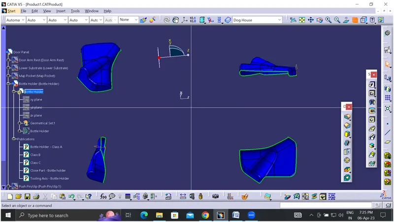
No surface discontinuity
Tooling Axis:
Creating a correct tooling axis is important to manufacture the component.
Based on the tooling axis only we performed the draft analyze and check whether the part manufaturable or not.
In this project we have used two types of tooling axis method.
- Point and direction
- Master section base creation
Arm Rest:
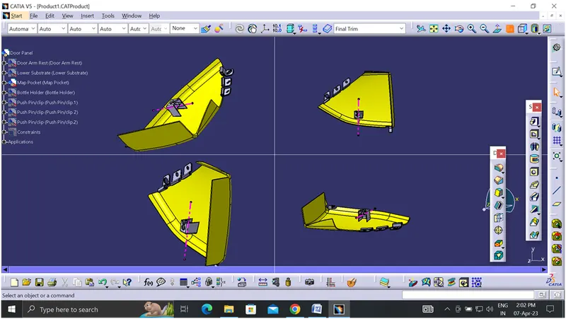
We have the master section of flange in the arm rest. When we check the master section the main tooling axis direction is parallel to the "Z" direction.
So take point on the extract and using line command option draw the line in "Z" direction.
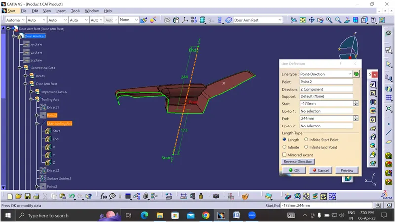
Main tooling Axis : Z Direction
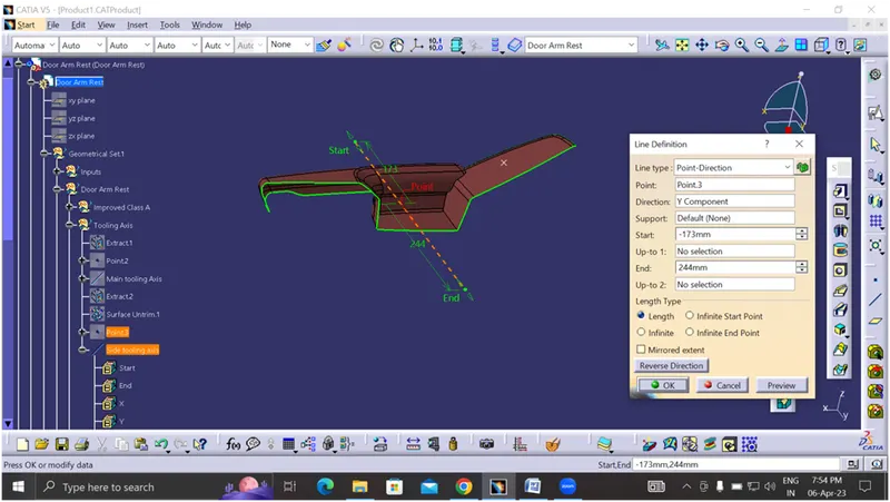
Mean while have to work in the creation of side core axis, why because the arm rest not clear the main tooling axis alone. It has made of two components, so we have to create a side core axis also.
Like the main tooling axis, have to check the master section the side direction is parallel to the Y direction. Hence take a point from the extract surface in the direction of "Y"
Side core axis : Y Direction
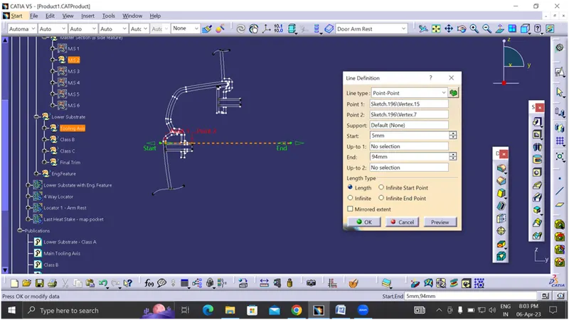
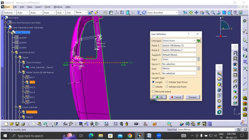
Lower Substrate:
It's clear to see that from the master section the tooling axis is parallel to the Y direction. So just refer the master section and take a reference of two points and create a line it's parallel to the Y axis.
Main tooling Axis : Y Direction
Map Pocket:
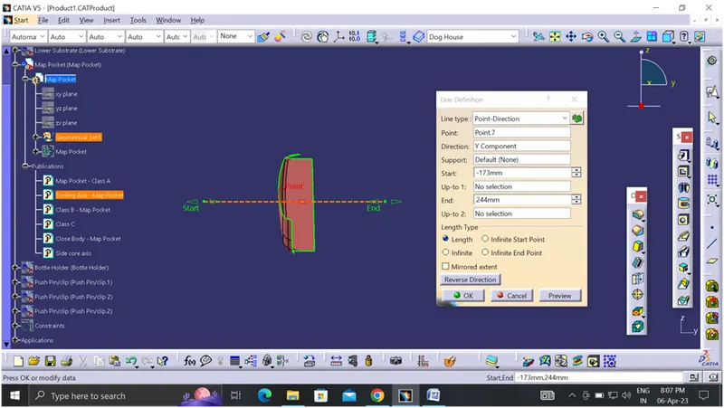
Same as like the lower substrate the tooling direction is parallel to the Y direction. So create a line in the direction of "Y" and name it as Main Tooling Axis.
Main tooling Axis : Y Direction
Bottle Holder:
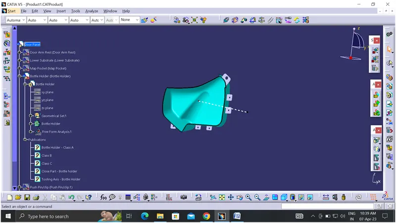
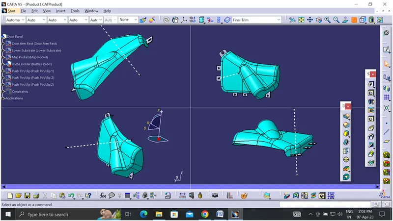
In that area we don’t have any master section. So we check whether which direction its going to be clear. We take a comparison of neighbor component. All other 3 components will make a tooling direction along Y only. So in bottle holder also take a point and create a tooling axis along the Y direction.
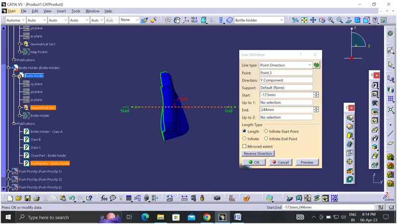
Tooling Axis : Y direction
Draft analysis:
Draft Analysis is used to analyse whether given product model is manufacturable or not. There is at least some minimum Draft angle should given for each and every product, so that the mould and part making minimum point of contact when the ejection time. It also reduces the part getting affected by the mould.
After creating the Tooling Axis, it's mandatory to check whether our given class A Surface will clear the draft analysis or not.
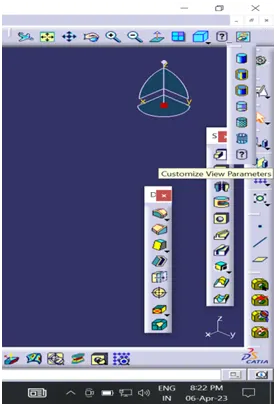
To perform the draft analysis should change some setup.
- Select the "Customize View Parameters" and select the "Material" option
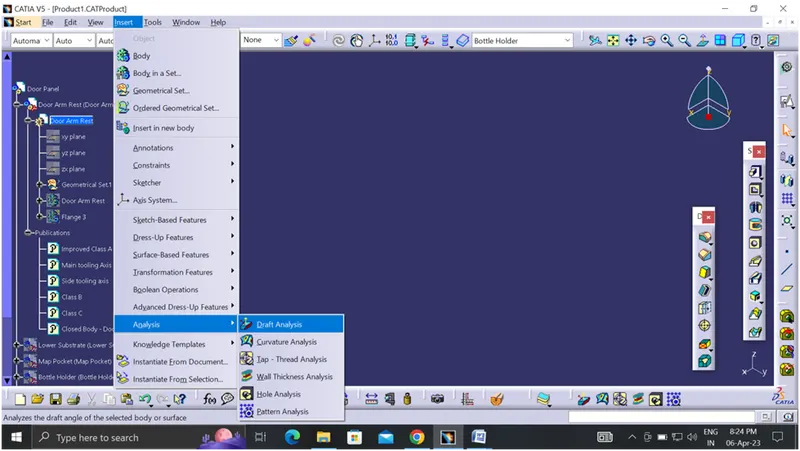
- Select the Insert > Analysis > Feature Draft Analysis
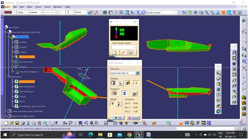
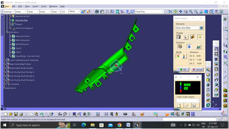
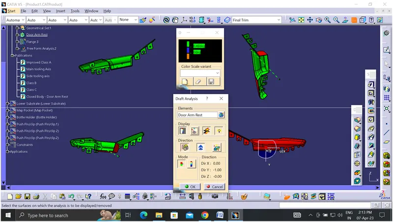
- Click the "Compass" icon and drag the compass on the Tooling axis and make the draft angle as 3 deg. If the Draft angle is more than 3 deg. It shows a Green colour and 0 deg it shows in Blue colour. If the Draft angle is less than 0 deg its shows in Red colour.
Arm Rest:
Main Tooling Axis
Place a compass on the main tooling axis and select the Class A Surface. It's clearly visible that maximum portion will clear the draft analysis. But some areas are not clear the draft and it also shown in negative draft. In that area will clear in the side core axis.
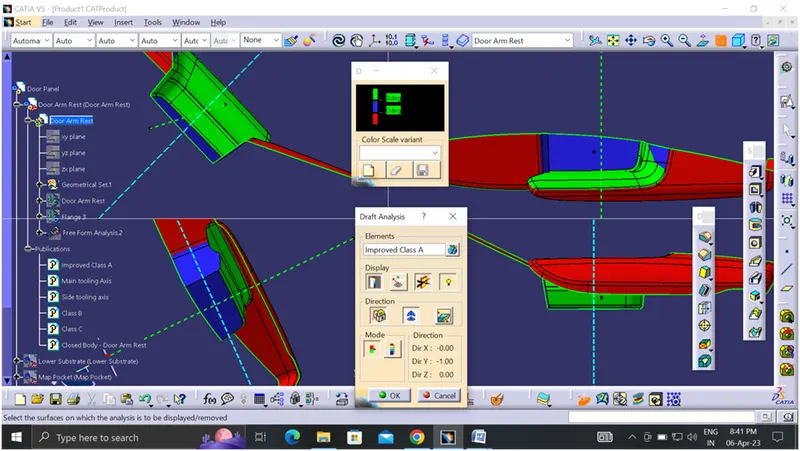
Side Core Axis
Combination of two tooling axis Class A surface clears the draft analysis.
Lower Substrate:
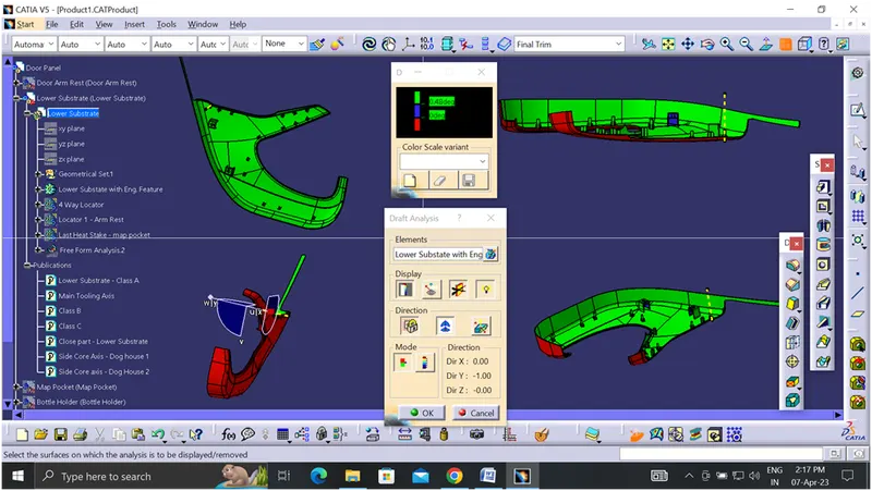
Lower Substrate is clear the draft analysis at 3 degree.
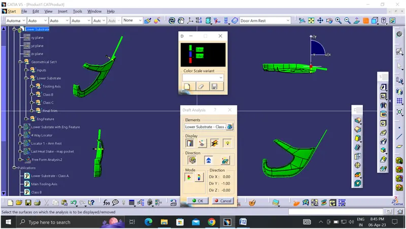
Map Pocket:
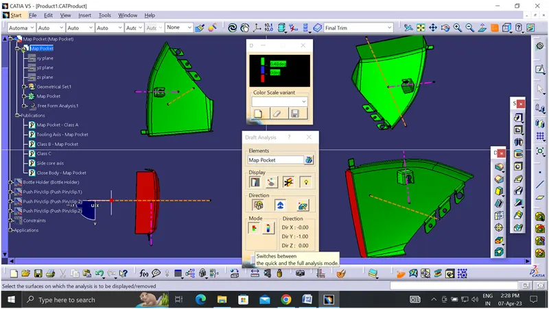
Map pocket clears the draft analysis at an angle of 3 degree.
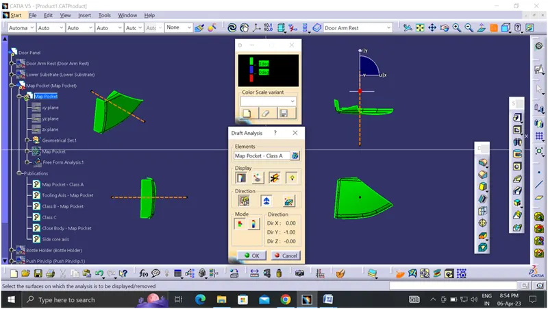
Bottle Holder:
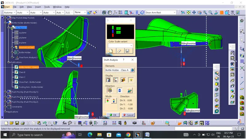
Bottle Holder clears the maximum area of draft analysis, but in some area shows in blue color why because it has no draft area in class A.
In this case we follow the same surface to continue for part creation of B Surface and C surface.
"B" Surface Creation:
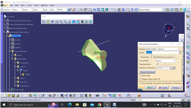
We need to create the B surface at a distance of 2.5mm in every single individual class A surface.
Creation of B surface is important because all the engineering features (like Dog House, Ribs, Screw boss etc are placed in the B surface area)
Arm Rest:
When taking the offset of class A surface some patches are missing. We have to work on the missing patches using multi section and sweep command.
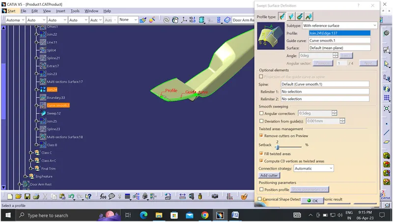
Finally fix the class B surface and make a complete one.
Lower Substrate:
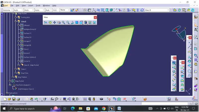
Map Pocket:
When try to offset the class A surface of Map pocket some patches are missing. We recreate the patches using extract command and extrapolate the surface and trim it. Then we get the Class B surface.
Bottle Holder:
C Surface Creation:
Creation of C surface will be performed in two to three methods.
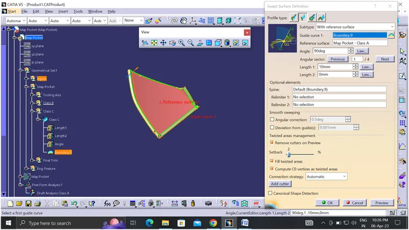
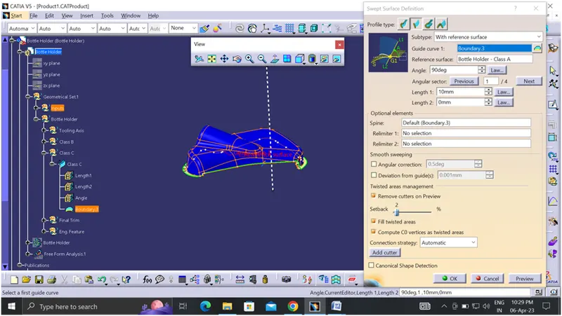
Profile type 1: Reference surface
Profile type 2: Draft direction
Profile type 1: Reference surface
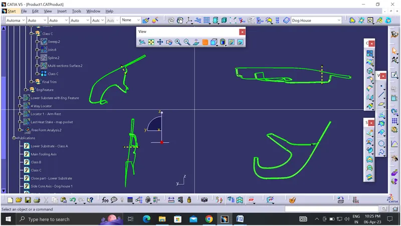
Arm Rest:
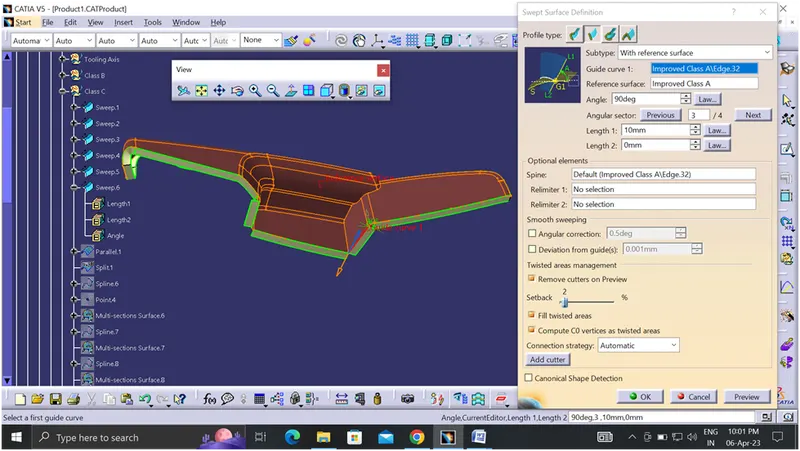
When creating the C surface for arm rest first take flat surfaces of the arm rest and creating the c surface using Profile type 1: reference surface method
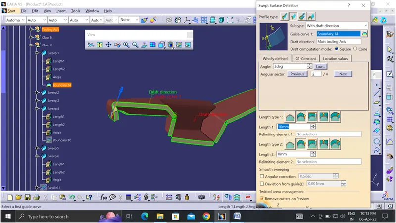
Then take an other surface using profile type 1: draft direction method and keep the surface angle at 3 degree.
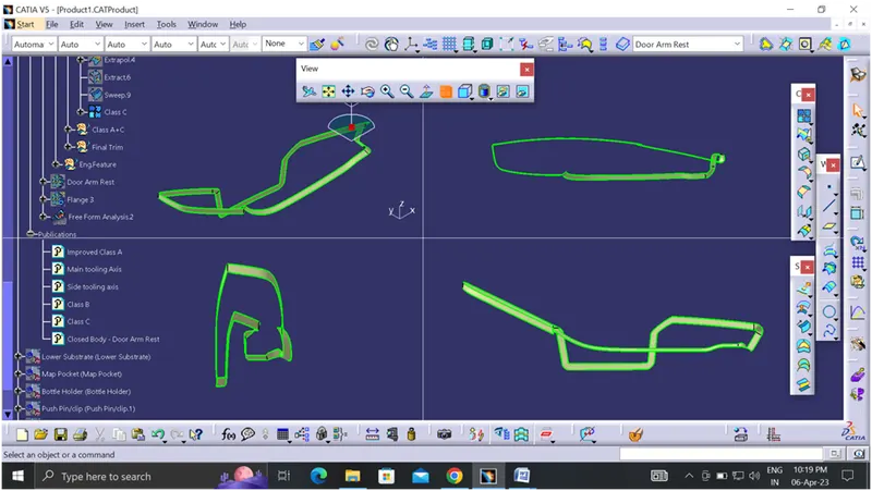
Then using multi-section creates the patches after that join the surface using trim option. Finally create the C surface perfectly.
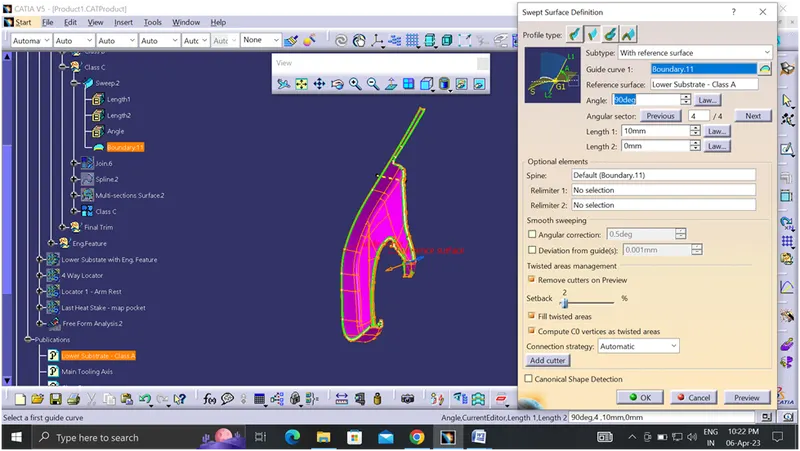
Lower Substrate:
Using Reference surface method creates the C surface of Lower substrate and join the surface in multi section.
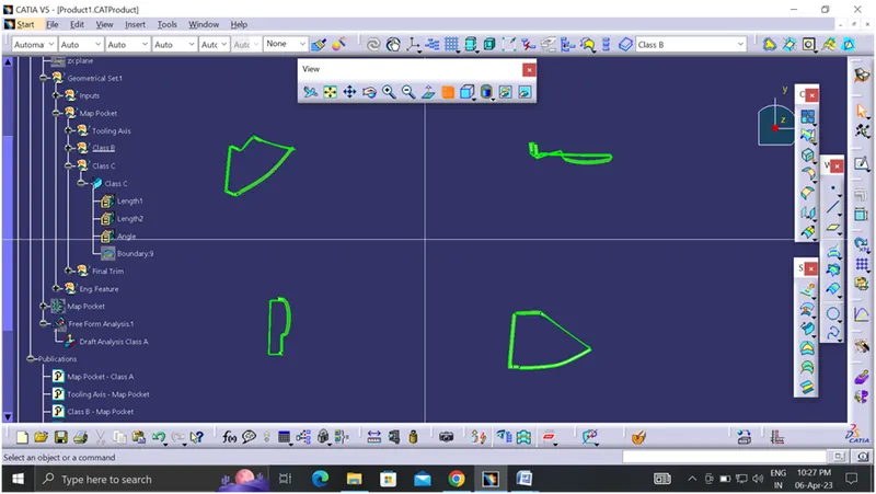
Map Pocket:
Bottle Holder:
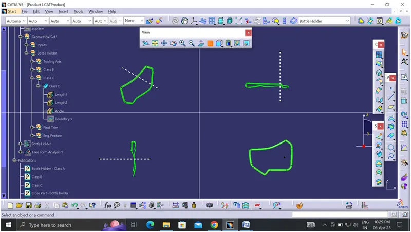
Joining of A+ C Surface:
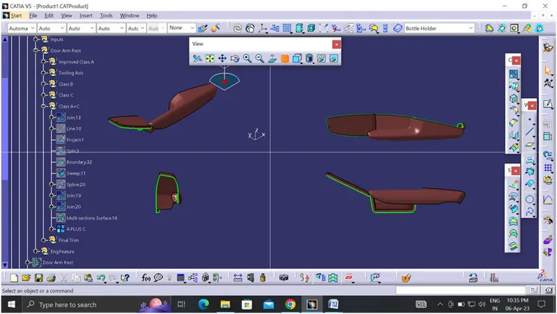
Arm Rest:
Join the Class A and Class C Surface. Some areas are not properly joining so remove the patches and recreate it using multi section.
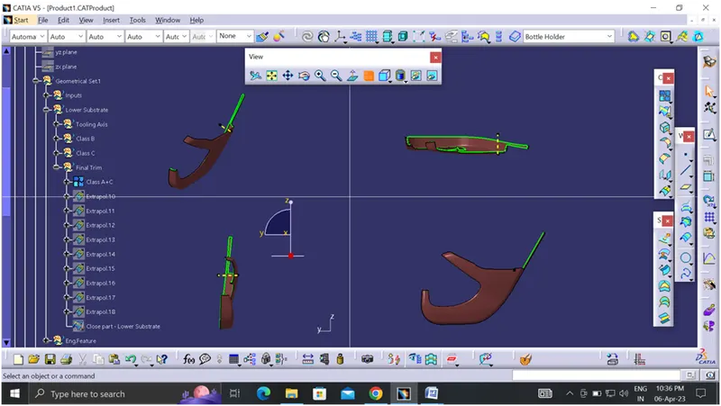
Lower Substrate:
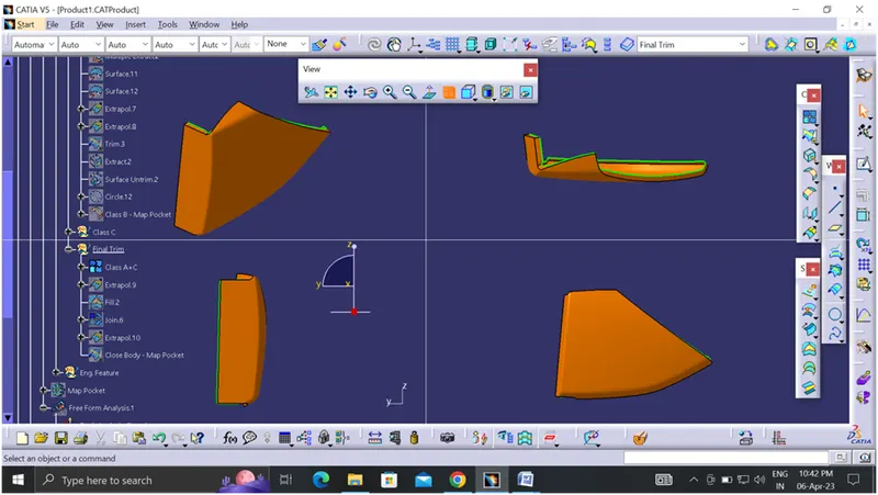
Map Pocket:
Bottle Holder:
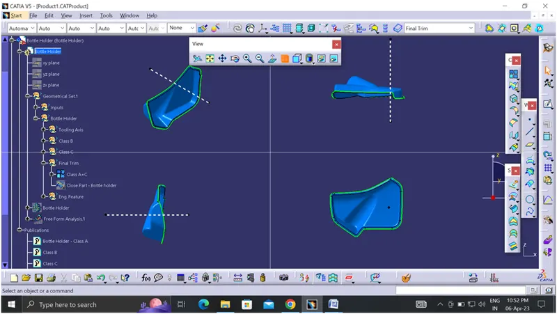
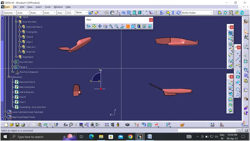
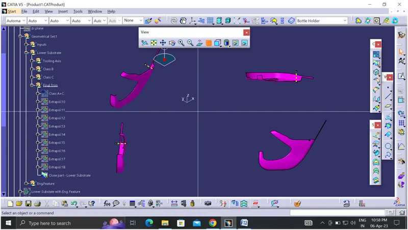
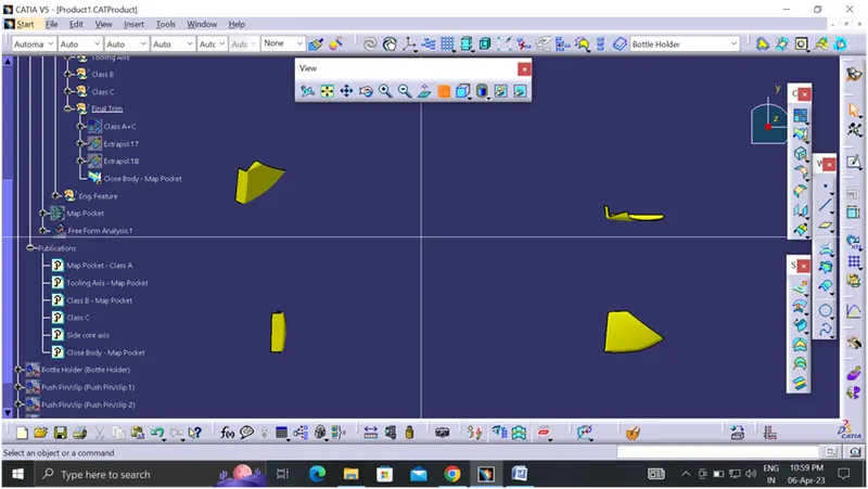
Final Trim (Closed Body):
Extrapolated the B surface at some distance then trim with class A+C surface for creating the Closed Body.
Arm Rest:
Lower Substrate:
Map Pocket:
Bottle Holder:
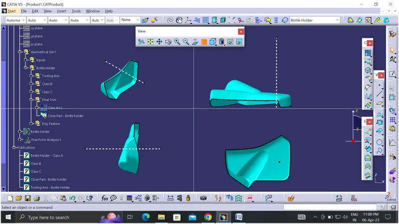
Surface to Solid body conversion:
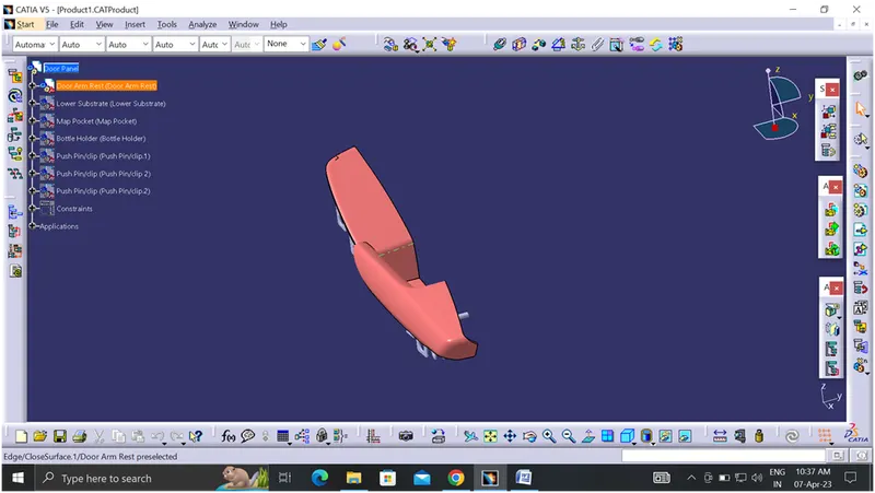
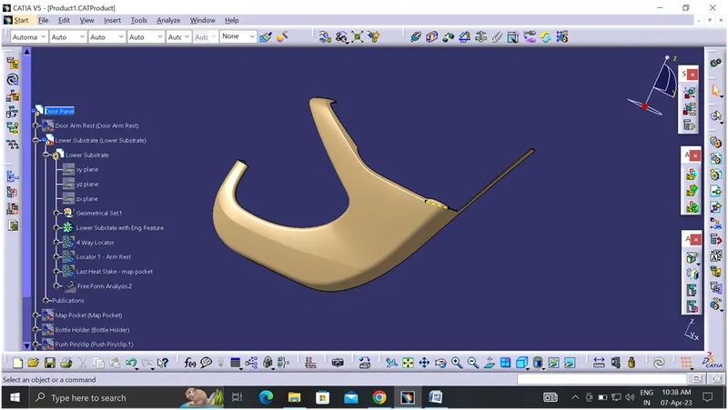
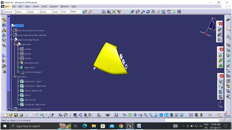
Conversion of Surface model into solid part will be performed in the part workbench.
Using close surface command all the closed part converted into solid part.
Arm Rest:
Lower Substrate:
Map Pocket:
Bottle Holder:
Engineering Feature Creation:
In-order to reduce the Sink mark on the plastic component, we used some extra part on the B side of the plastic component.
- Ribs,
- Screw Boss,
- Dog House
Some features are used to join or hold the two different parts
- Heat stake
- Flanges
In this project we create the entire component with their dimension.
Heat Stake:
Heat staking also known as thermoplastic staking is the process of joining two dissimilar materials together. In heat staking we use local heating and cooling to raise the temperature of plastic components and allow plastic reforming to be carried out. This reforming can be used in a wide variety of applications.
Applications range from staking plastic boss’s for assembly of car door panels to joining PCB’s to plastic housings. Benefits of this technique include; no vibration damage, no particulates, the ability to stake metalized coated applications and the capability to stake in difficult to access or restricted areas.
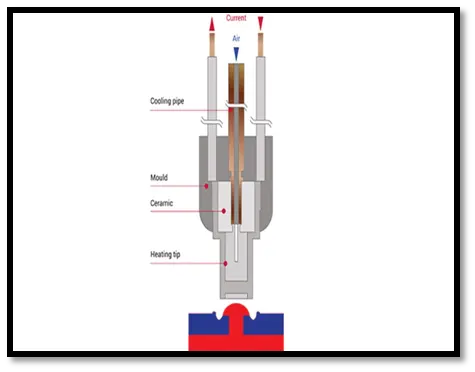
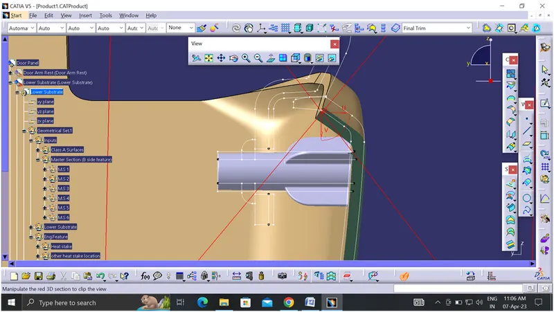
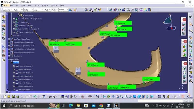
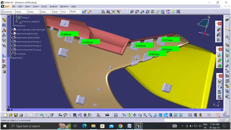
In this particular project we have master section for the heat stake. So we created the heat stake as per that and translate it in other area. Lower Substrate is the Larger area among the other parts so we need to place the heat stake in that and as per heat stake location we created the flange to hold the other parts with the help of flanges.
Minimum distance between the two heat stakes is 50mm, and all the heat stakes are same height from the base.
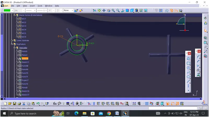
We provide ribs for the heat stake for extra strength. Create the minimum draft of 0.5 degree in Ribs and heat stakes.
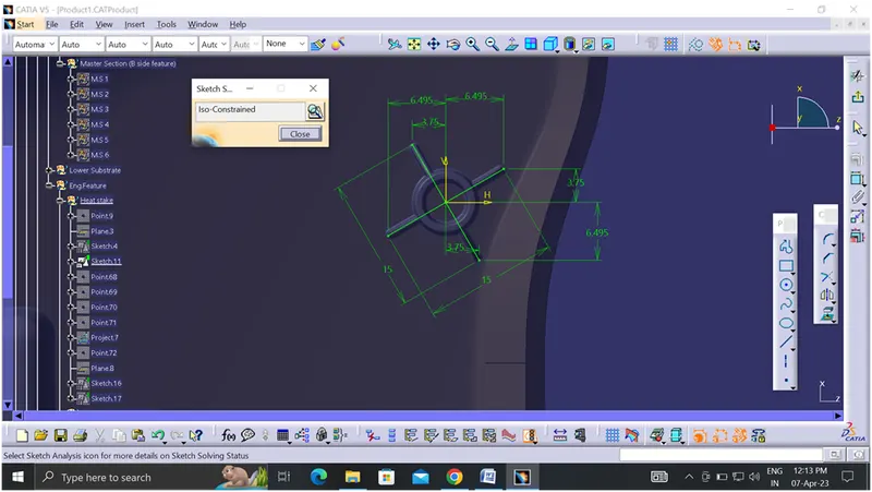
When all the heat stakes are created once, and then join it with lower substrate using union trim command.
Flanges:
Heat stake alone can't join the parts it requires flanges also. We have master section for flange creation based on that creates it.
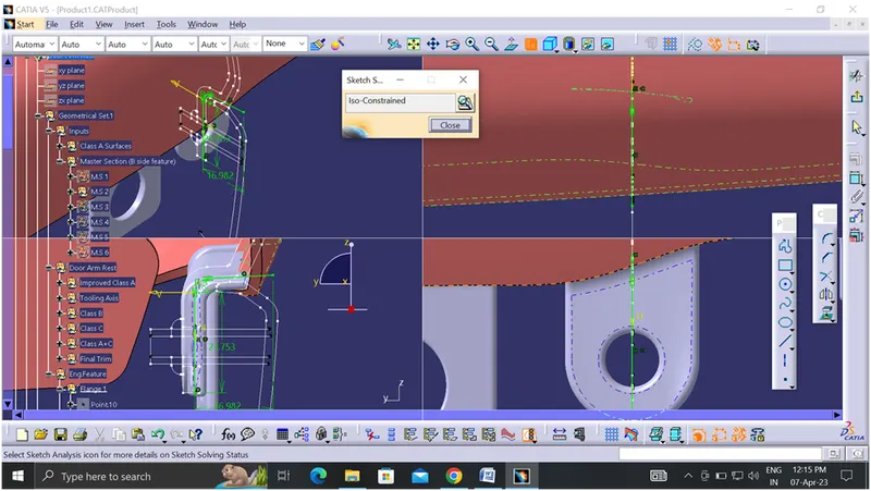
Once we created the sketch using sweep option to with reference curve option create a surface and thicken the surface
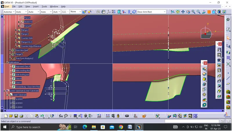
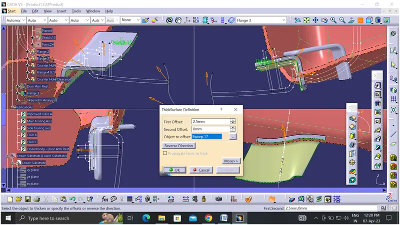
We don’t have specific dimension for flanges but approximately the flanges need 30mm width.
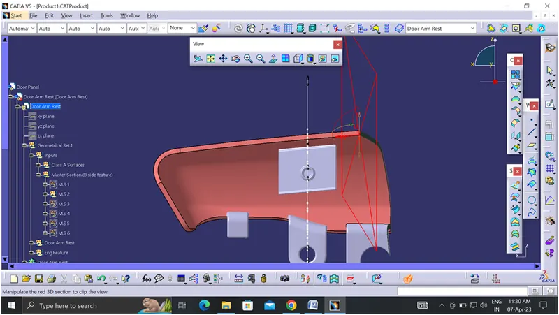
But in real life problem we unable to create the flanges with the specific dimension some areas are more curvy in that specific area we limited the flange width.
For Example:
In arm rest we have master section of the flange as per dimension it's created. But we can't create the flange width its 30mm, because the flange placed surface is curvier so the flange not comes in the perfect shape. So we limited the width and make the flange only for holding purpose only not going to fix the heat stake on it.
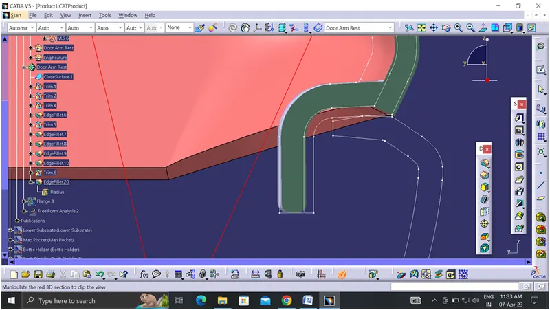
Due to small surface the flange is going weak if we placed the heat stake in it.
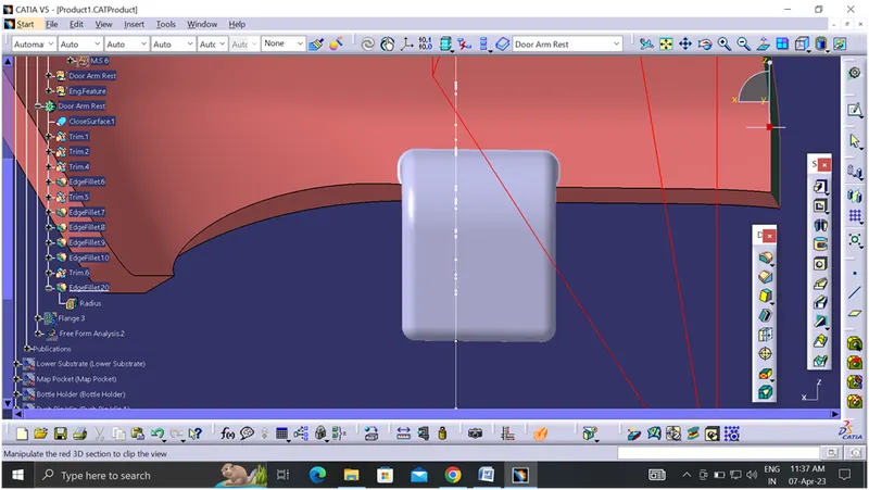
All the flanges have minimum draft of 0.5 degree and make the clearance hole on it for placing the heat stake. Clearance hole between heat stake and flange is 0.5mm.
Locators:
BASIC PRINCIPLES OF LOCATING
To perform properly, work holders must accurately and consistently position the work piece relative to the cutting tool, part after part. To accomplish this, the locators must ensure that the work piece is properly referenced and the process is repeatable.
The Mechanics of locating
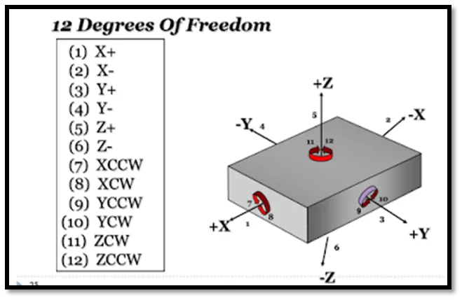
A work piece free in space can move in an infinite number of directions. For analysis, this motion can be broken down into twelve directional movements, or "degrees of freedom." All twelve degrees of freedom must be restricted to ensure proper referencing of a work piece.
As shown in Figure 3-1, the twelve degrees of freedom all relate to the central axes of the work piece. Notice the six axial degrees of freedom and six radial degrees of freedom. The axial degrees of freedom permit straight-line movement in both directions along the three principal axes, shown as x, y, and z. The radial degrees of freedom permit rotational movement, in both clockwise and counterclockwise radial directions, around the same three axes.
Locators provide a positive stop for the work piece. Placed against the stop, the work piece cannot move. Clamps, on the other hand, rely only upon friction between the clamp and the clamped surface to hold the work piece. Sufficient force could move the work piece. Clamps are only intended to hold the work piece against the locators.
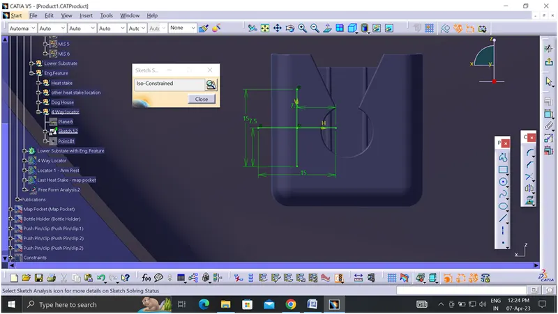
Once the sketch is completed using pad option to extruded the sketch and provide minimum draft of 0.5 degree and also provide edge fillet radius of 0.25mm.
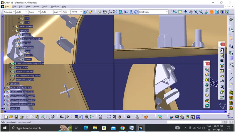
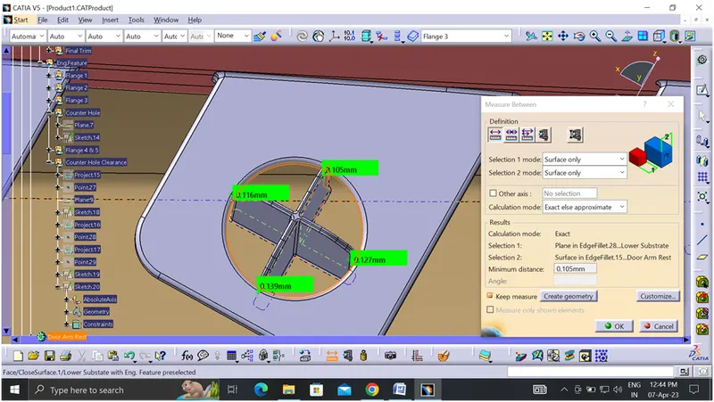
Counter hole clearance for the flange and locator is 0.1mm.
Dog House:
Dog house is an engineering feature used in plastic trim design. Dog houses are used as supporting feature. Sometimes other engineering features like snaps; locators etc. are mounded on them to increase their strength. Dog houses are subjected to draft analysis to prevent breakage of the component during ejection from mould cavity. Dog house and other engineering components are built on B-surface
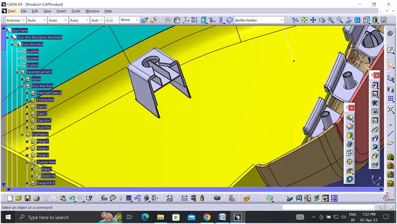
The basic sketch for dog house is created then pads it and shells it. Draft provide for outer walls is 1.5 degree.
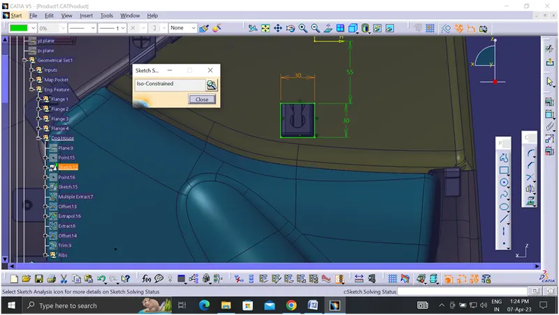
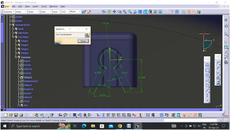
Create a hole cut out on the top of the dog house to hold the Pushpin. Which is used to fix the BIW component to the plastic.
Then take a extract of outer wall and offset it inside will make the inner core thickness is at least 40% of wall thickness of component.
Take the extract of bottom surface of the component which is going to hold the dog house and trim it with the offset surface. Split the trim surface with the dog house to create the inner core at a height of 3 to 6mm.
Take a point on the inner surface and create a line normal to the surface. This line will be the side core axis of the dog house. Create a draft of 0.5 degree throughout the inner walls.
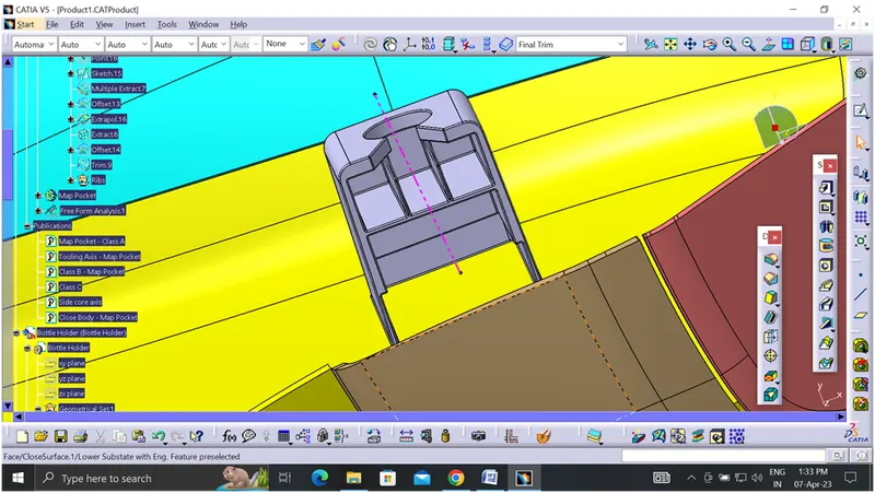
Create the Ribs for the dog house. Once the sketch is completed pad it and draft 0.5 degree along the side core axis. Then union trim with dog house in order to get complete design.
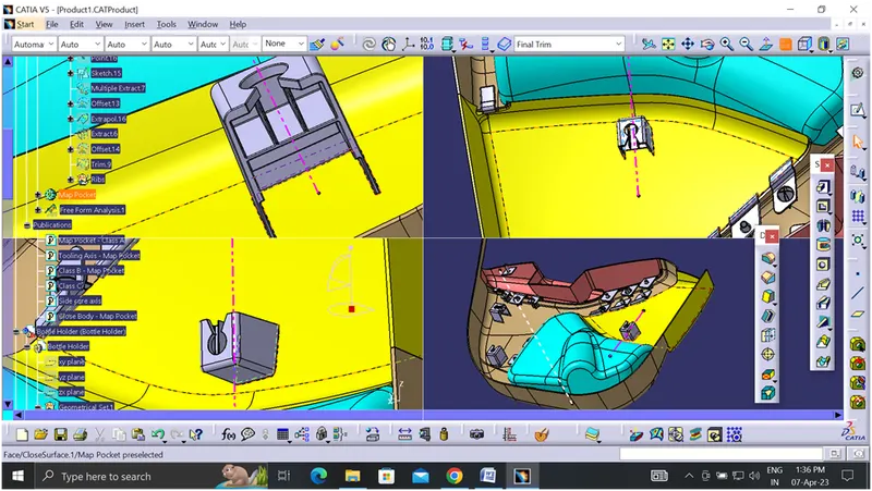
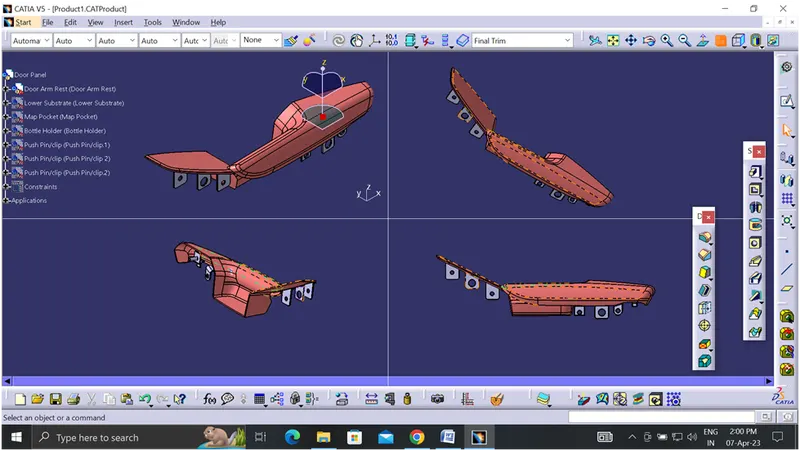
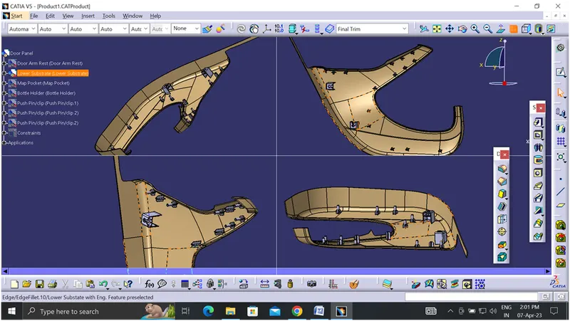
Once all the engineering feature are created all the parts are union trim with the respective parts
Arm Rest:
Lower Substrate:
Map Pocket:
Bottle Holder:
Final draft analysis (Parts with Engineering Feature)
Arm rest:
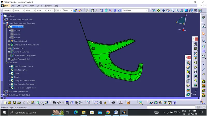
Lower Substrate:
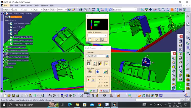
Dog House draft analysis:
Map Pocket:
Bottle Holder:
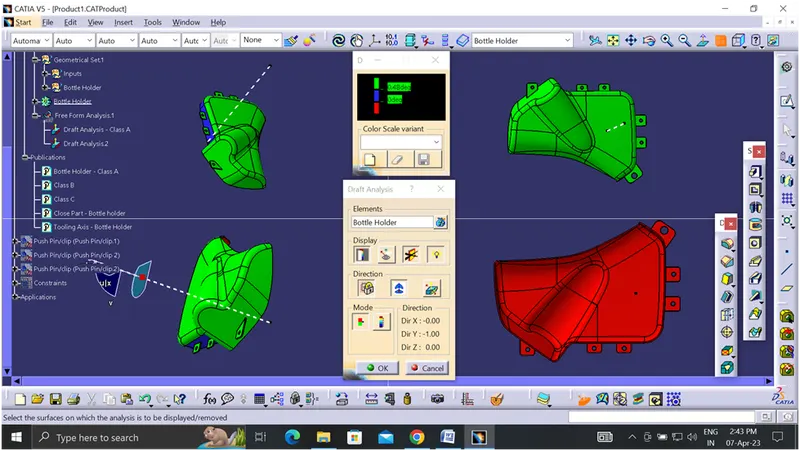
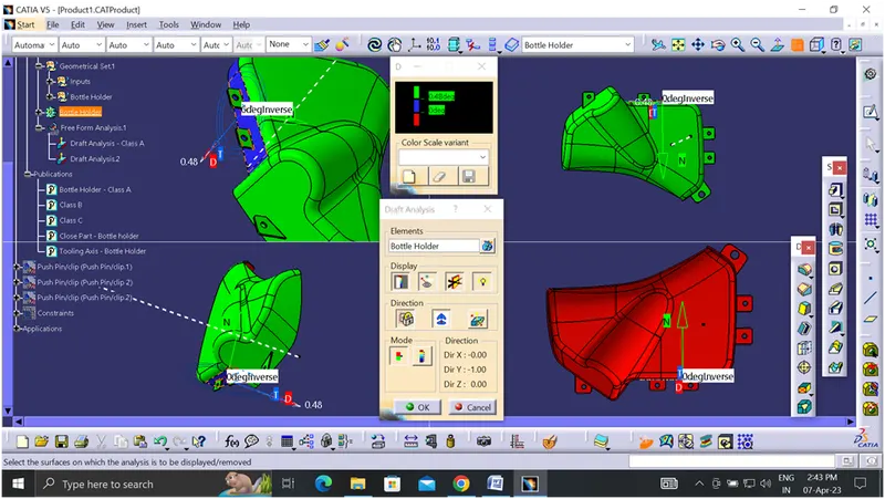
Like class A surface solid part also have some no draft area
Constrain for parts:
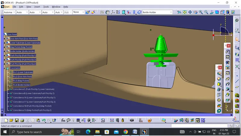
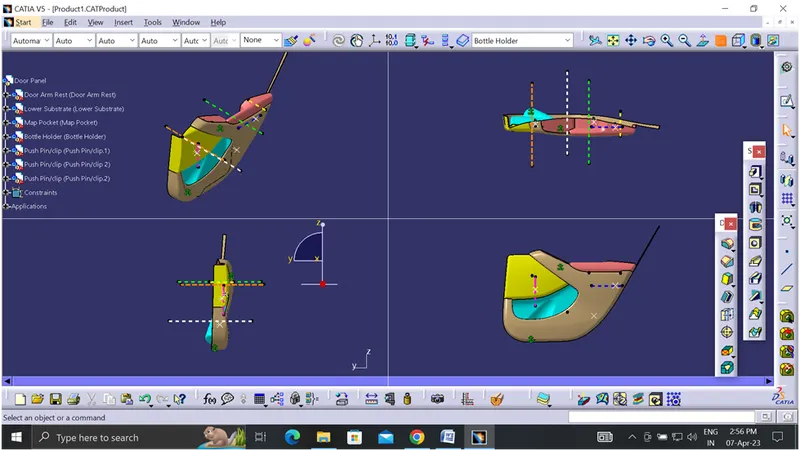
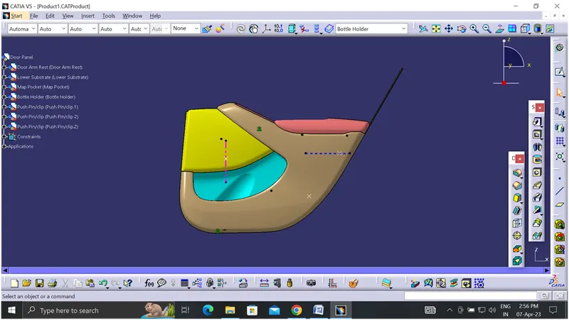
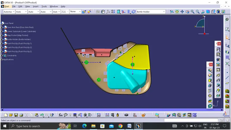
Go to the assembly workbench and give constrain to the parts. Fix constrain used for all the parts. Then coincidence constrain given for Pushpin axis to the dog house top circle axis.
Then give coincidence constrain to the top of the dog house and pushpin surface