Fender Design - Wheel Arch Challenge
Fender Wheel Arc
Aim:
To measure and give report to the design team, whether the given fender designs meet the required parameters based on European standards.
Fender:
Its primary purpose is to prevent sand, mud, rocks, liquids, and other road spray from being thrown into the air by the rotating tire. Fenders are typically rigid and can be damaged by contact with the road surface. Most modern vehicles have fenders on their front wheels. When you get into a minor car accident, you can call it a "fender bender," and it's possible that your fenders did get slightly dented.

Wheel Arch:
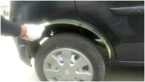
It is a semicircular profile above wheels designed for enclosing tire within the fender. The wheel arch is designed considering all possible motions the tire undergoes while the vehicle is in motion. The wheel arch also ensures stopping any debris that could possibly fly outside the wheel well and hit pedestrians.
Fender Design consideration:
For design a fender we have to take one of the most important considerations is “Wheel arc calculation”.
The calculation is differing from region to region. In this challenge we are going to proceed with European standards. But we have to know what other region standards are.
Japan Standards:
As per Japanese standards, the clearance between tyre and fender must be greater than 5mm.
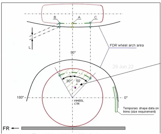
In the picture, from the wheel centre vertical axis point. Two lines should be created and should be having 30 degrees to the left and 50 degrees to the right from the centre axis. Then on projecting the line on to the wheel arch, the distance (L as shown in the figure) between the intersecting points on the wheel and the wheel arch is allowed to have a minimum of 5mm distance at all three points (A, B and C). This is the Japanese standard.
United States Standards:
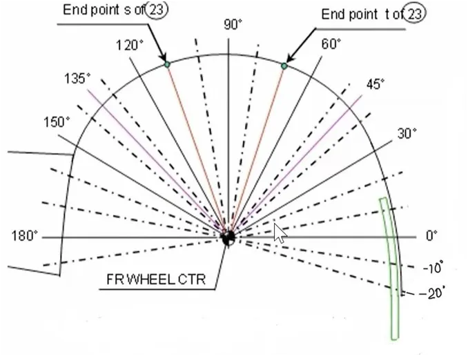
For united state, the concept is the same but the point should be taken on every 10 degrees from -20 degree to 0 and a minimum gap between the wheel and wheel arch should be 5 mm at all of those points. This is the United States requirement.
European Standards:
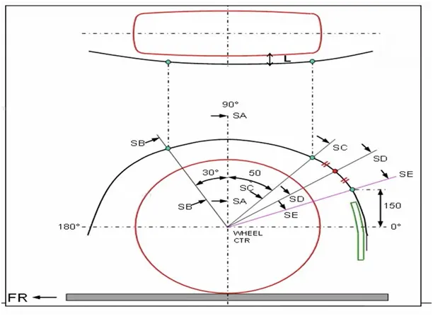
As like as Japan, Three lines SB, SA and SC should be created and should be having 30 degrees to the left for SB, SA passing 90 degrees through the centre axis and 50 degrees to the right from the centre axis for SC.
Then after creating those three lines, a 150 mm point should be marked on the wheel arch reference and a line should be created from the centre point passing through the point on the wheel arch reference. That line is called SE. Then another line should be created intersecting SC line and SE line. Then on projecting the line on to the wheel arch, the distance (L as shown in the figure) between the intersecting points on the wheel and the wheel arch is allowed to have a minimum of 10mm distance at all the points.
Why every region have different region and what should we follow?
Based on their country road condition, they have different set of standards.
If the same car design is done for different markets for example Japan, Europe and US, the we cannot make different designs for a same car, so we consider the maximum clearance value which will cover most of the regional requirements.
In this case we have to consider European design standards.
Wheel arc calculation: European Standards
- Create the datum plane of the Outer most side of wheel.
- Make the centre of the wheel circle.
- Draw horizontal and vertical perpendicular axes from the centre of the wheel circle.
- Draw lines at 30 degrees and 50 degrees from the centre.
- Make a point on the fender line at 150mm from the horizontal.
- Extend a line to this point from the centre.
- Then make a line that is exactly between the 50-degree line and the line made on the 150mm point.
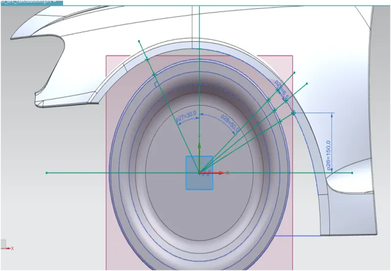
To Measure “L”:
- Condition: Point “B” >= 10 mm
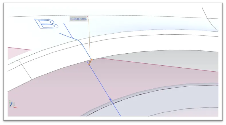
Point “B” = 10 mm
Result – Pass
- Condition: Point “A” >= 10 mm
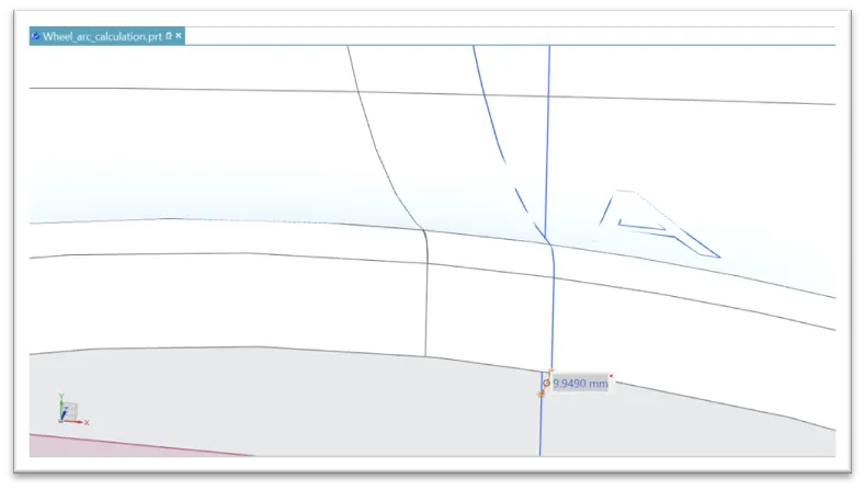
Point “A” = 9.94 mm
Result – Fail
- Condition: Point “C” >= 10 mm
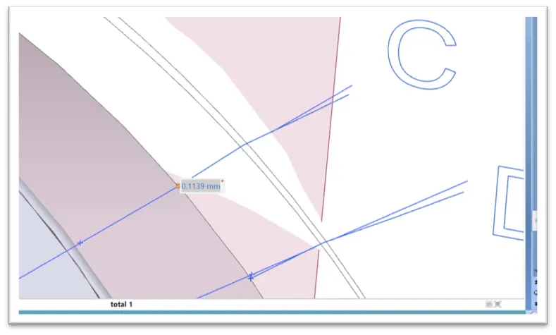
Point “C” = 0.11 mm
(Wheel comes out from fender area so consider as “Negative Value”)
Result – Fail
- Condition: Point “D” >= 10 mm
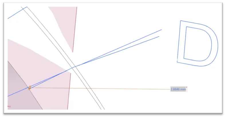
Point “D” = 2.88 mm
(Wheel comes out from fender area so consider as “Negative Value”)
Result – Fail
- Condition: Point “E” >= 10 mm
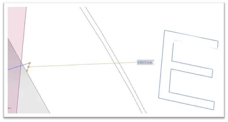
Point “E” = 5.99 mm
(Wheel comes out from fender area so consider as “Negative Value”)
Result – Fail
Table:
|
Outer curve of fender to wheel outer face |
Distance “L”
|
Obtained value
|
Result |
|
Point “A” |
>= 10 mm |
9.94 mm |
Fail |
|
Point “B” |
>= 10 mm |
10 mm |
Pass |
|
Point “C” |
>= 10 mm |
-0.11 mm |
Fail |
|
Point “D” |
>= 10 mm |
-2.88 mm |
Fail |
|
Point “E” |
>= 10 mm |
-5.99 mm |
Fail |
Conclusion:
- Point “A” only meets the exact European standards. All other points are not in the European standard.
- Hence the fender design needs to rework by the styling team.