Week 12- Final project
The given Door trim panel has a four majar parts. These are
- Arm rest
- Lower substrate
- Map pocket and
- Bottle holder.
1. Arm rest :
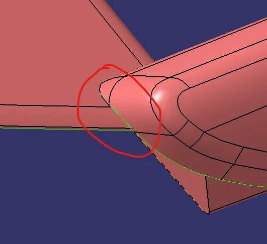
- First I was check the given class A have any open patch.
- If it have a open patch, then work on to correct the problem.
- The arm rest have a open surface so we resolve the issue.
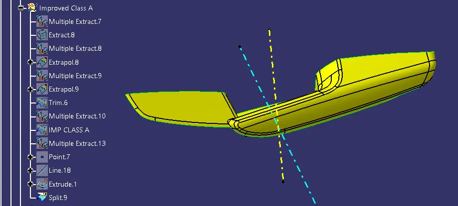
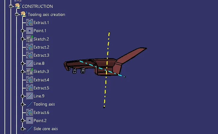
Tooling axis creation :
- And find which direction is suitable for create a tooling axis.
- In this part I use the bisecting method to create the main tooling axis.
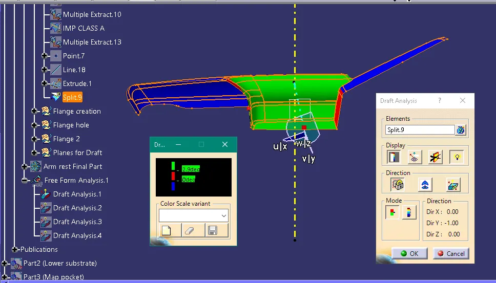
- Some areas are not clearing the draft analysis.
- So I create a side core axis for this part.
Draft analysis for given class A surface :
- Change the view to customize view and change the material then give ok.
- Click the compass and place on the main tooling axis.
- Then click on the class A surface.
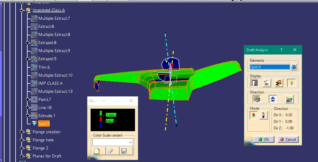
- The inside area is not clearing the draft analysis.
- So create the side core axis and place the compass on the side core axis.
Class B surface creation :
- First I check the mastersection to find the thickness of the part.
- Then offset the class A to 2.5mm.
- Some areas are not forming to create a open patch.
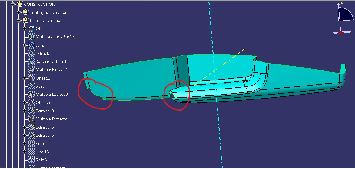
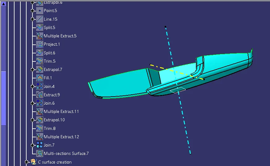
- I make a multisection surface to clear one patch.
- And encounter the another path by using extract, extrapolate, split, trim and join commands.
Class C surface creation :
- First create a separate boundary of the class A surface.
- Do the sweep with reference surface for which edge is parallel to the main tooling axis.
- And do the sweep with draft direction for which edge is perpandicular to the main tooling axis.
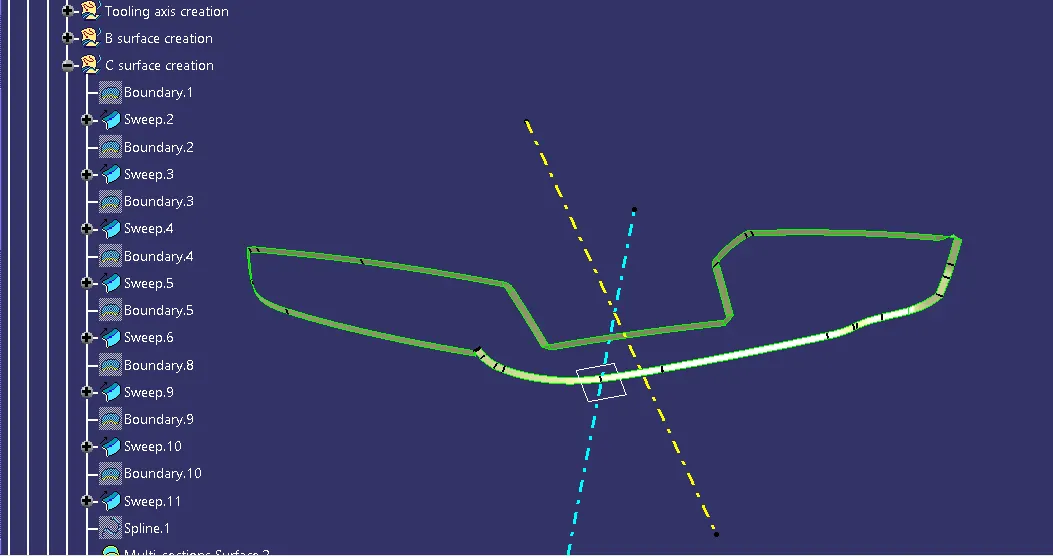
- Some curvature areas sweep cannot create so use the multi section suface to make the suface.
- And use the trim and join command to make the full Class C surface.
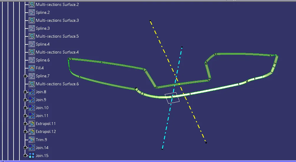
Class A and C join :
- Use the join command to join the Class A and C.
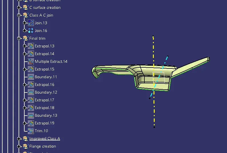
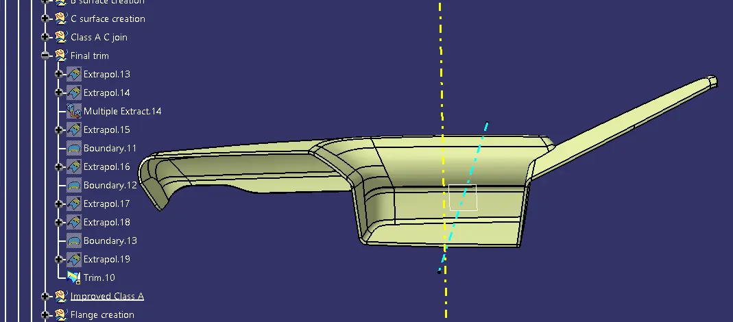
Final trim :
- Then extrapolate the edges of the class B and AC join.
- Make the intersect to trim them.
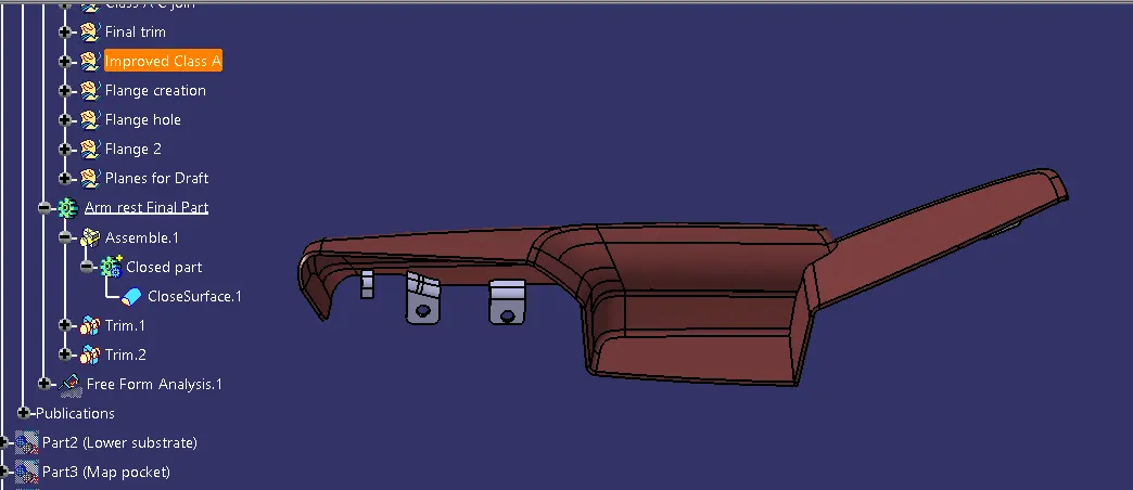
Closed part creation :
- And insert a new body and define that body as a working object.
- Then jump into the part design.
- Select the closed surface and select the trim.
- We get a closed part.
Draft analysis for closed part :
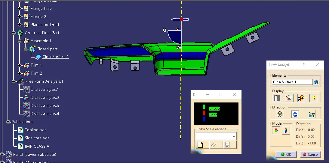
- Some areas not clearing the draft analysis.
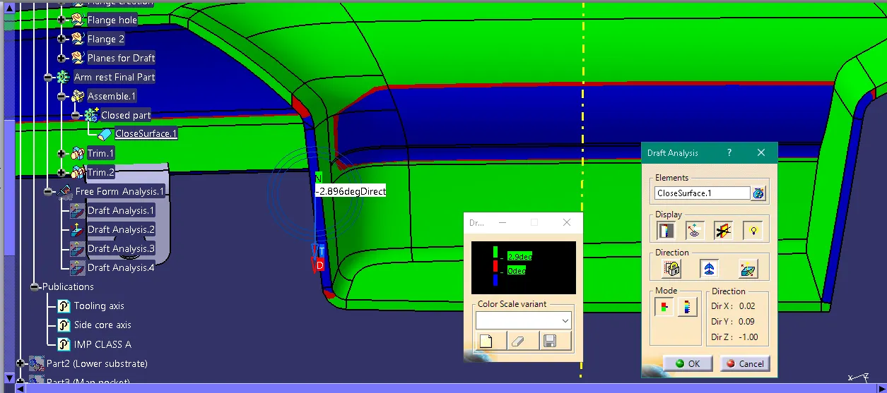
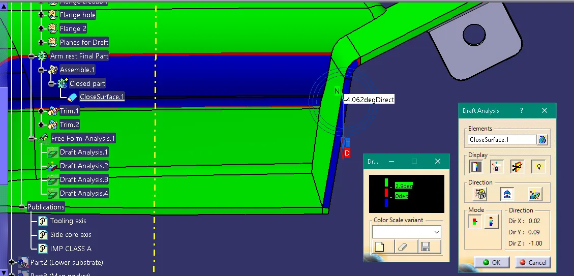
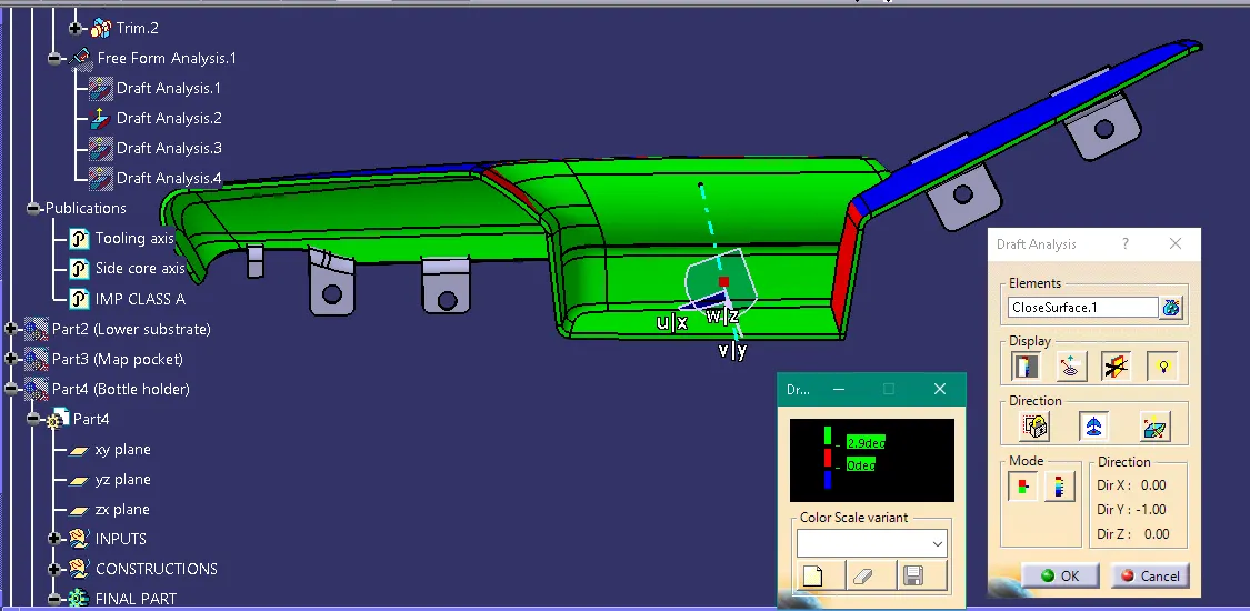
- Draft analysis with side core axis :
2. Lower substrate :
- First check the given class A have any open surface.
- In the lower substrate doesn't have open surface.
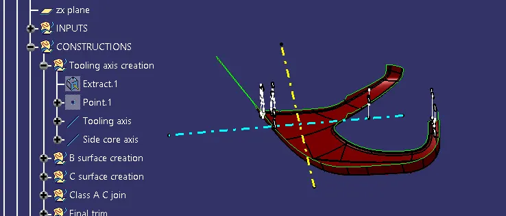
Tooling axis creation :
- Find which direction is suitable for creation tooling axis.
- In this part I simply give the line and direction to create the main tooling axis.
- Also some of the B side features will create on the part.
- So I create the side core axis for the B side features.
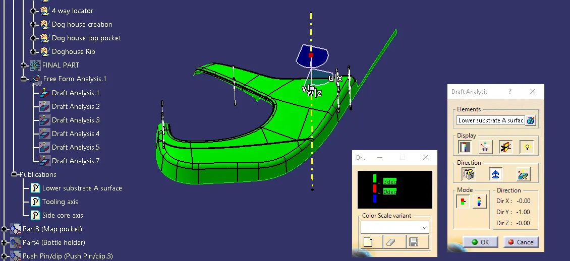
Draft analysis for Class A surface :
- First change the view to the customize and click the material then give ok.
- Select the feature draft analysis.
- Then click the compass and place it on the main tooling axis.
- And select the class A surface.
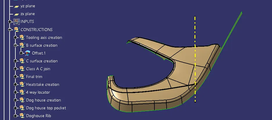
B surface creation :
- In the lower substrate part I simply offset the class A surface at 2.5mm.
- I doesn't create any problem.
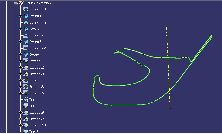
C surface creation :
- First I create a separate boundaries for sweeps.
- Use extrapolate to make them intersect.
- Then do the trim to make a single surface.
Class A and C join :
- To join the Class A and C surface using the join command.
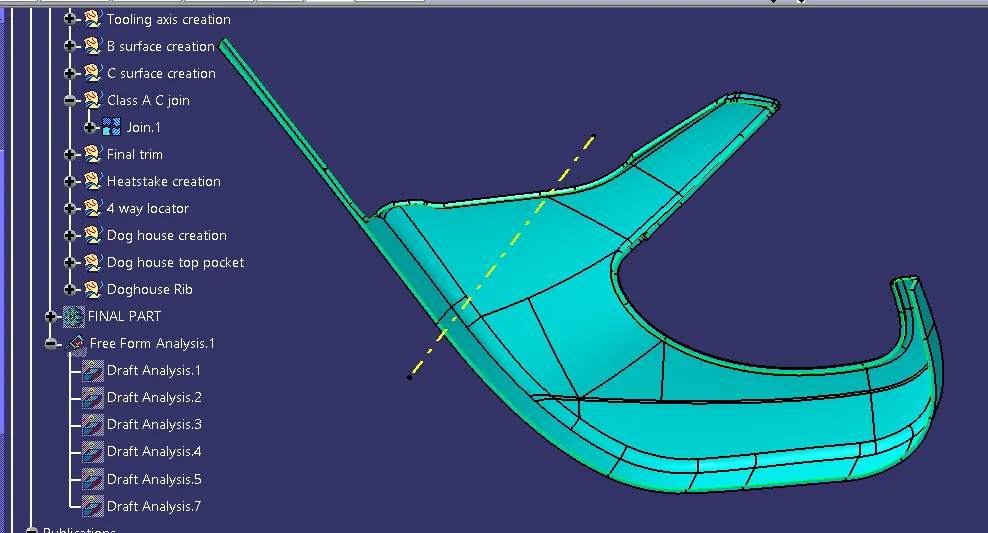
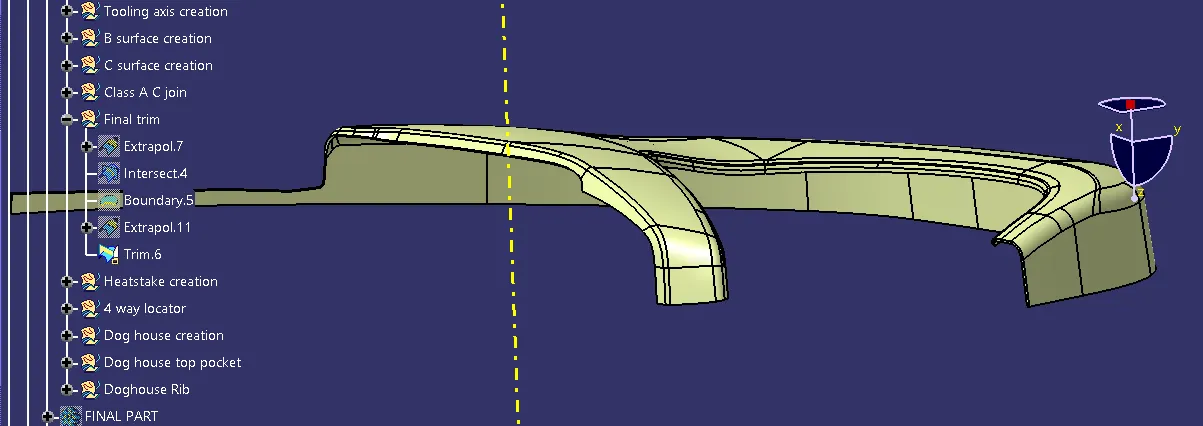
Final trim :
- Extrapolate the Class B and Class A C join to make them intersect.
- And do the final trim to get the closed surface.
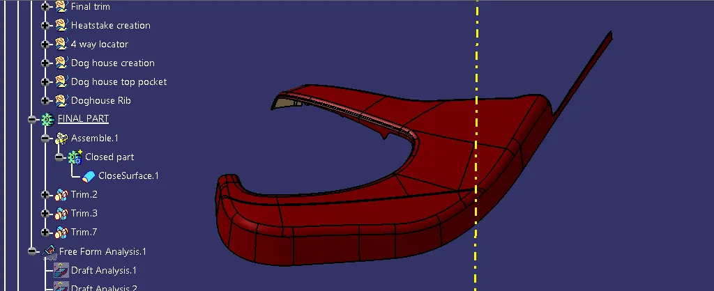
Closed part creation :
- Insert a new body and define as a working object.
- Then jump into the part design.
- Click the closed surface command select the trim and click ok.
- We get a closed part.
Draft analysis for closed part :
- First change the customize view to select the material then give ok.
- Select the feature draft analysis command.
- Click the compass and place it on the main toolling axis.
- And select the closed part.
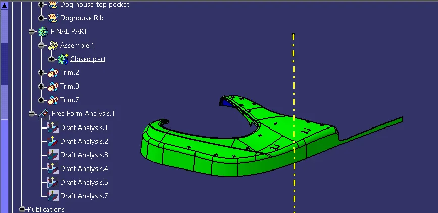
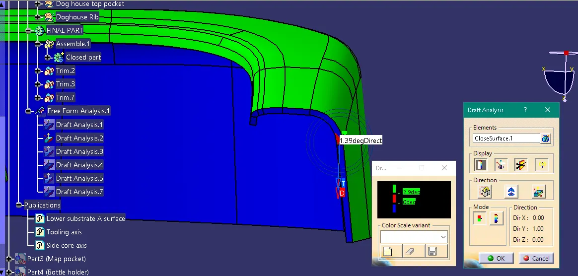
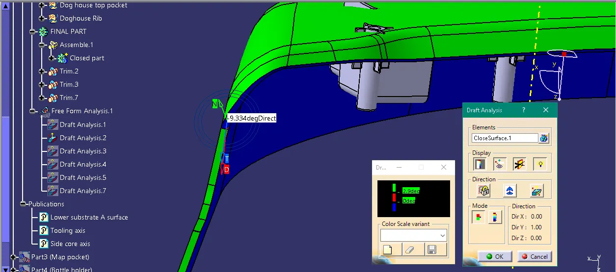
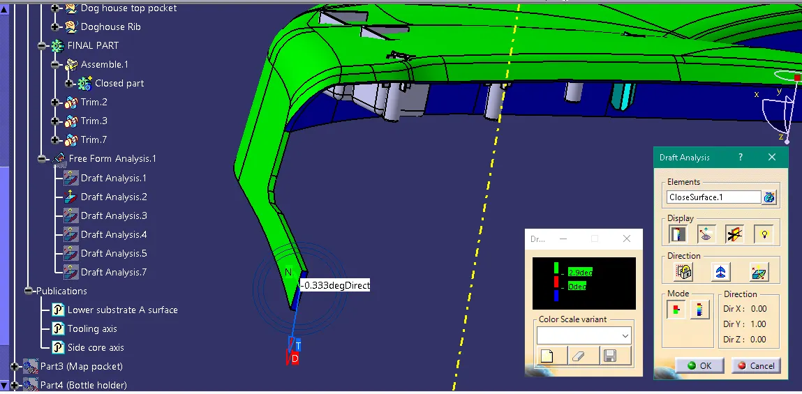
- Below some areas not clearing the draft analysis.
3. Map pocket :
- Always check the given class A have any open surface.
- In this map pocket doesn't have any open surface.
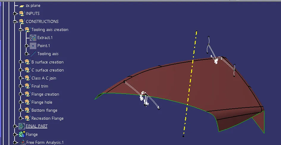
Tooling axis creation :
- Find which direction is suitable for creating the tooling axis.
- In this part I simply create a line with the direction.
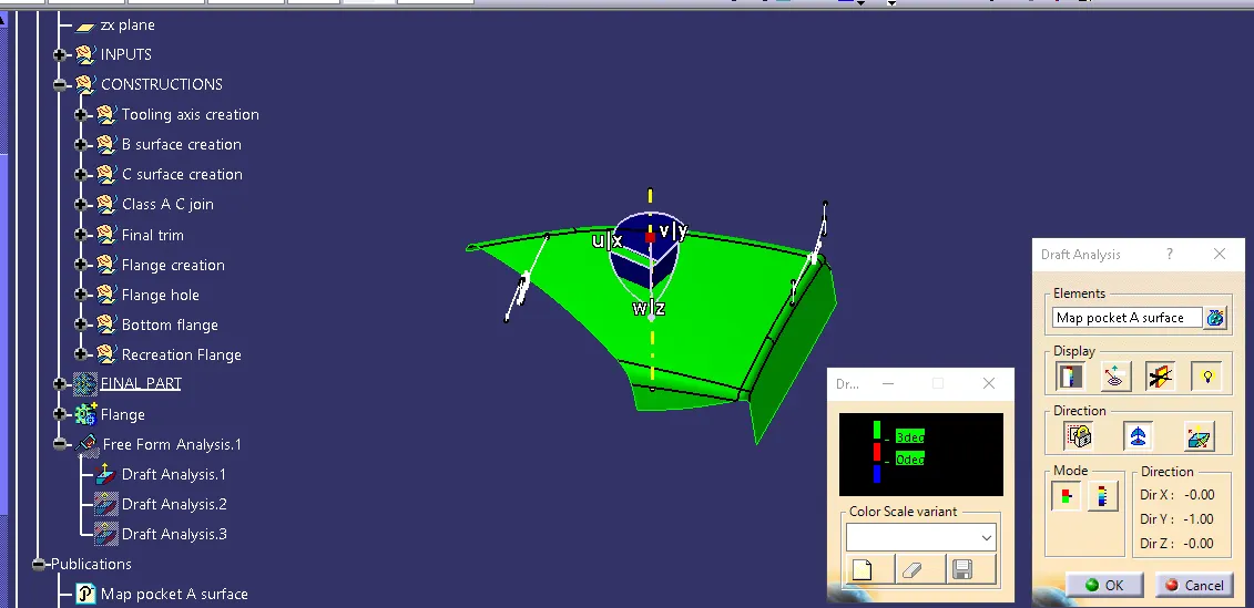
Draft analysis for Class A surface :
- First change the view to customize view and tick the material and give ok.
- Select the compass and place it on the main tooling axis.
- Then click on the class A surface.
B surface creation :
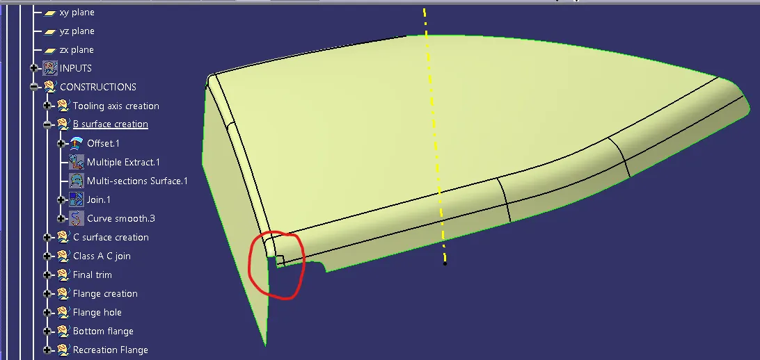
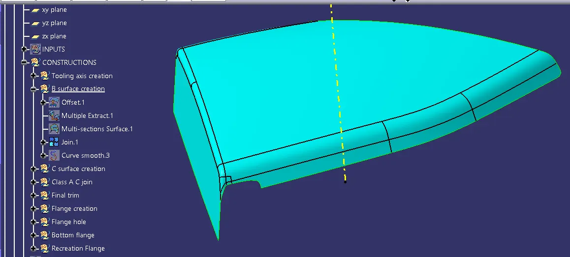
- Offset the class A at 2.5mm.
- It doesn't create one fillet surface.
- I create that surface by use the multisection surface.
C surface creation :
- Create a separate boundaries of class A to create a sweep.
- Use sweep with draft direction for which edge is perpandicular to the tooling axis.
- And use sweep with referance surface for which edge is parallel to the tooling axis.
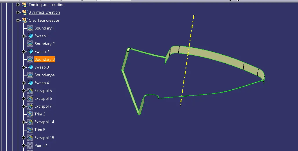
- Some areas not create, so use the multisection surface to create the surface.
- Then use the join command to join them.
- Use extrapolate command to intersect the surfaces to make the trim.
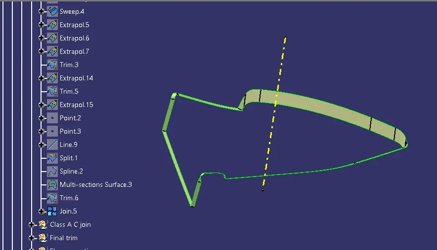
Class A and C join :
- Use the join command to join the class A and C surfaces.
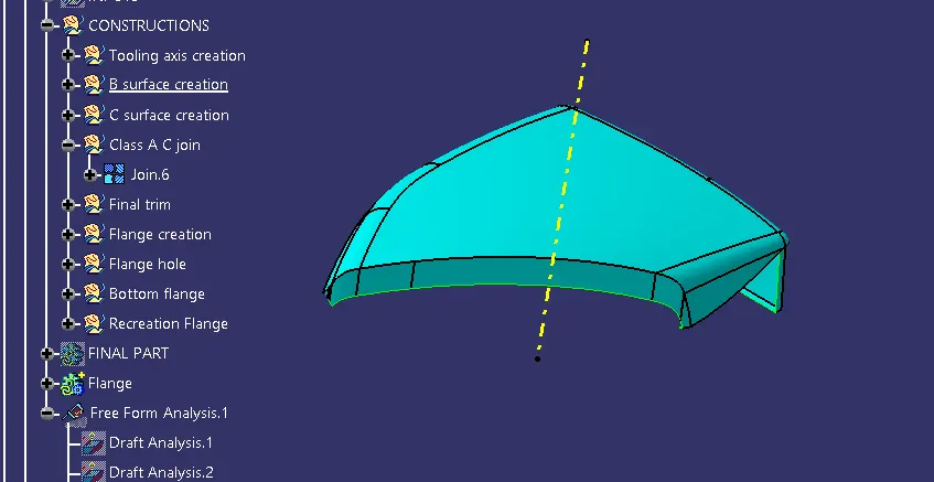
Final trim :
- Extrapolate the edges of Class A C join and Class B surface.
- Make them intersect then trim them to get a closed surface.
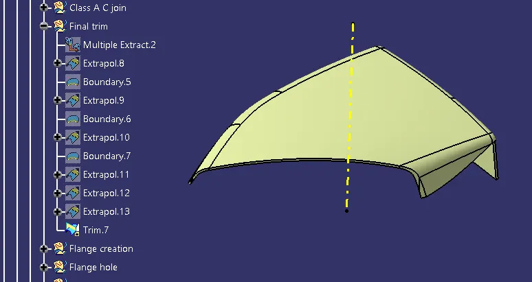
Closed part creation :
- Insert a new body and define as a working object.
- Then jump into the part design.
- Select the closed surface and select the trim to get a closed part.
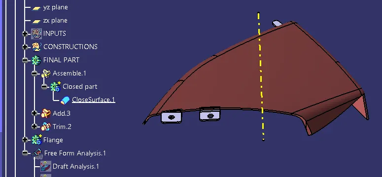
Draft analysis for closed part :
- First change the view to customize view and tick the material then give ok.
- Click the feature draft analysis.
- Select the compass and place it on the main tooling axis.
- And click on the closed part surface.
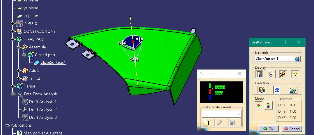
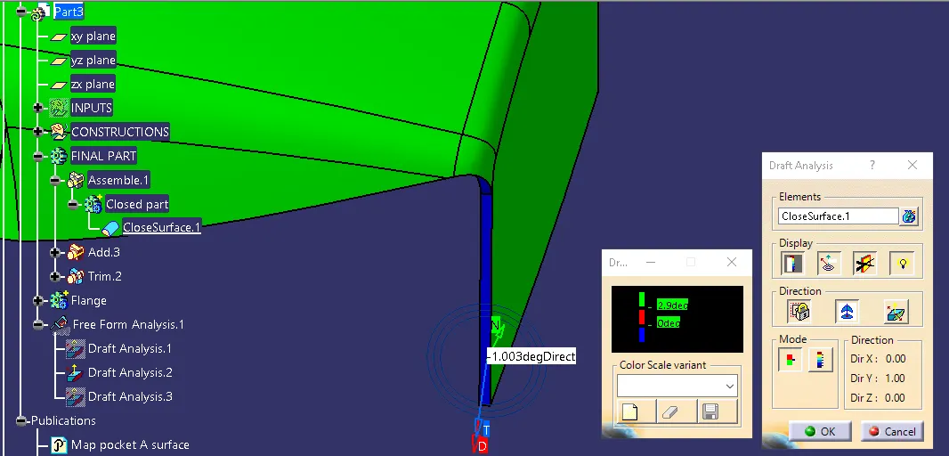
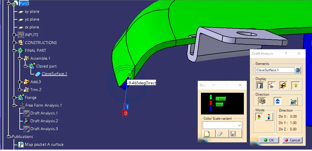
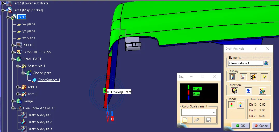
- Some surface doesn't clear the draft analysis.
4. Bottle holder :
- First check the Class A surface have any open surface.
- In that bottle holder doesn't have any open surface.
Tooling axis creation :
- Find which direction is suitable for creating a tooling axis.
- In this part I simply create a line with direction to make a tooling axis.
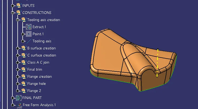
Draft analysis for class A :
- Change the view to customize view and click the material and give ok.
- Select the feature draft analysis.
- And click the compass and drag it to place on the tooling axis.
- Then click on the class A surface.
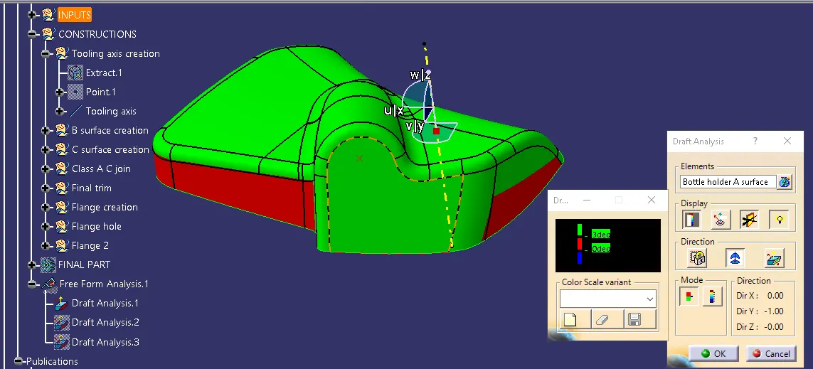
- Below some areas not clearing the draft analysis.
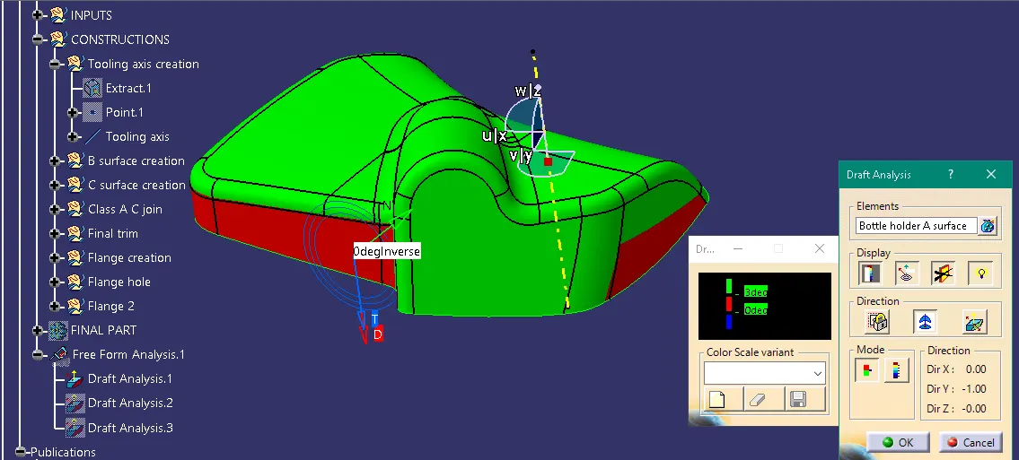
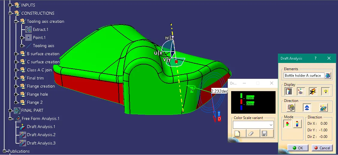
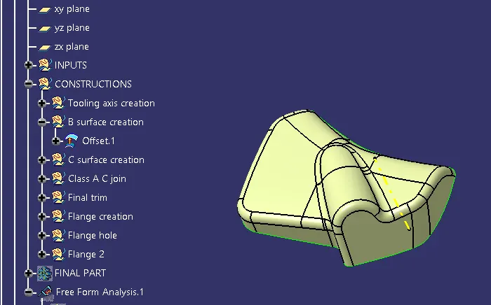
B surface creation :
- In this part I simply offset the class A surface at 2.5mm.
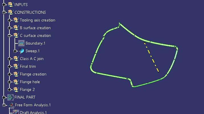
C surface creation :
- Do the sweep with referance surface to create a sweep.
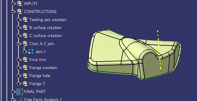
Class A and c join :
- Use join command to join the class C and A surfaces.
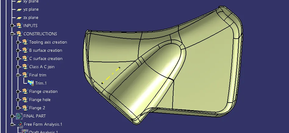
Final trim :
- Extrapolate the class A C join and class B surface.
- Make them intersect with each other to make a trim to get a closed surface.
Closed part creation :
- Insert a new body to define as a working object.
- And jump into the part design.
- Select the closed surface and click the trim to create the closed part.
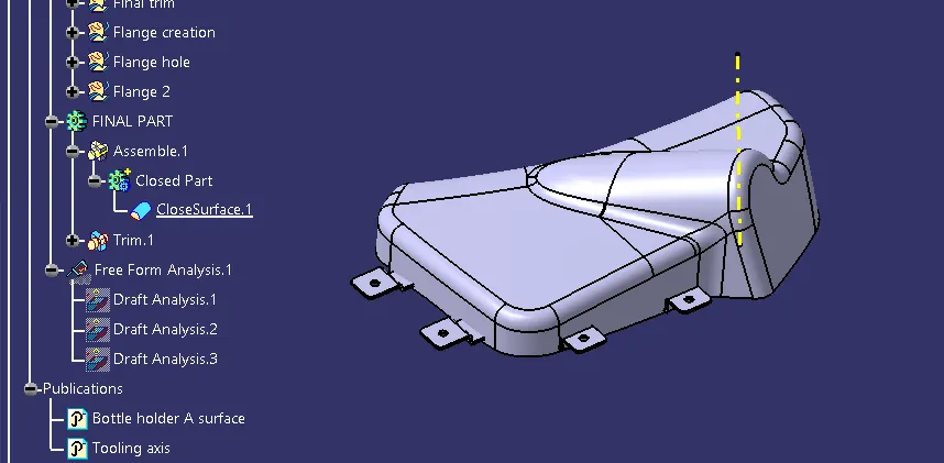
Draft analysis for closed part :
- First change the view to customize view and click material.
- And select the compass and drag to place on the tooling axis.
- Then click on the closed part surface.
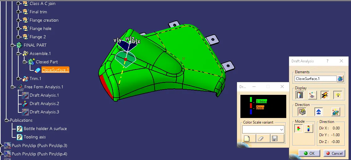
- Below some areas are not clearing the draft analysis.
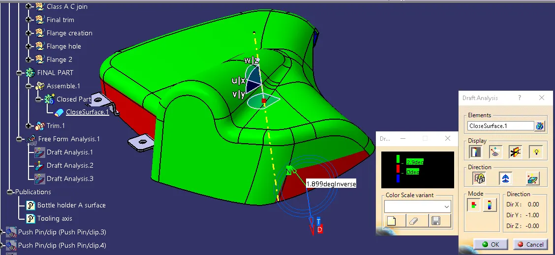
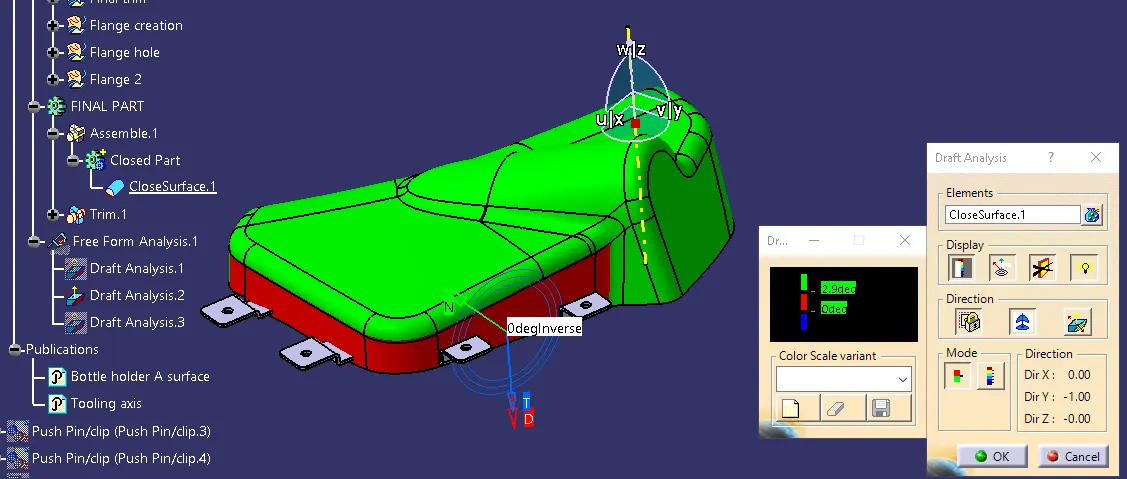
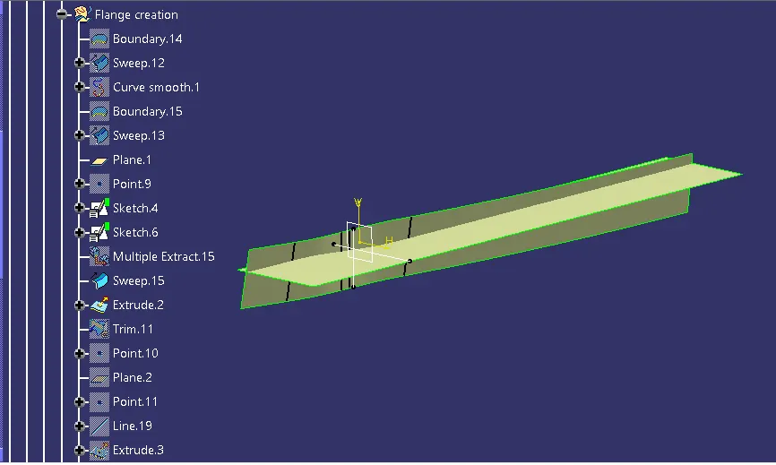
Flange creation in Arm rest :
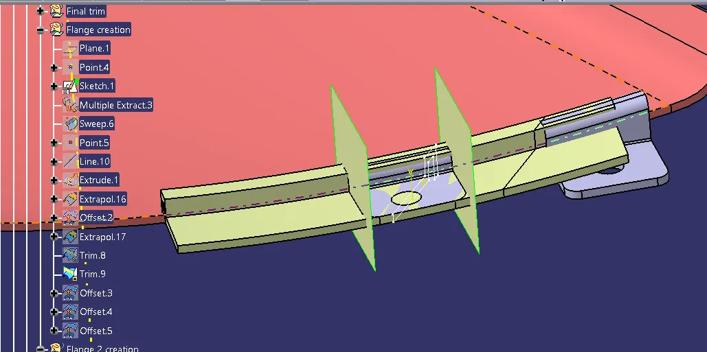
- First multiple extract the class C surface edge.
- Create a plane on that required area by using three point of master section.
- Also create a point on that center of the plane.
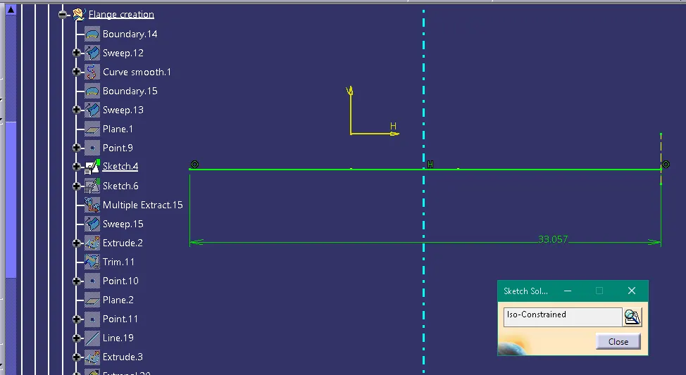
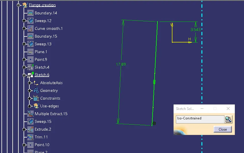
- Create a sketch with use the master section curves as a referance 3d object.
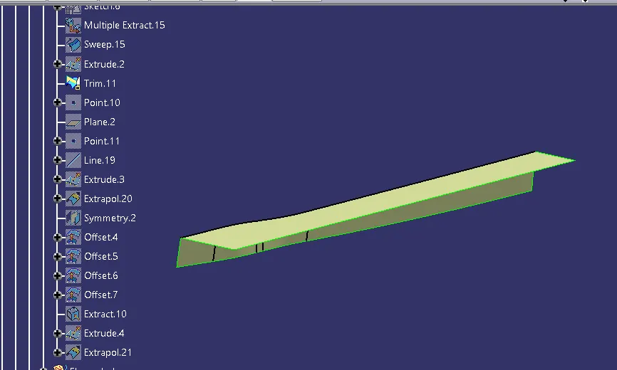
- Use the sweep explicit with referance surface.
- Give profile is a sketch and guide curve as a multiple extract edge.
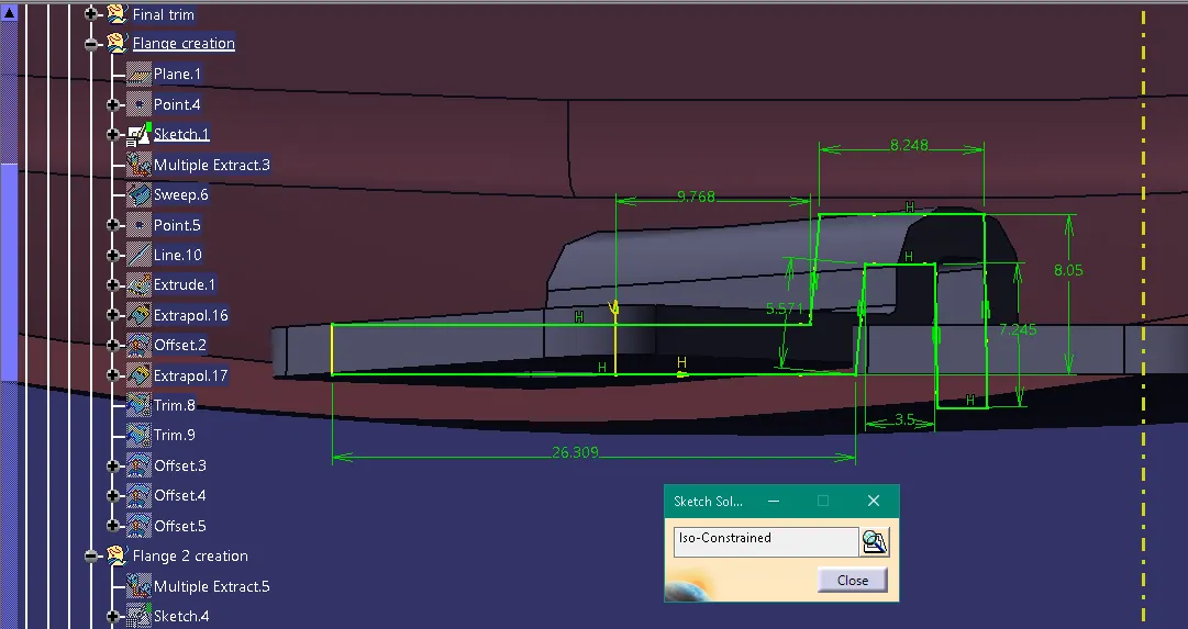
- And create another sketch for top surface.
- Then extrude the sketch.
- And make the trim.
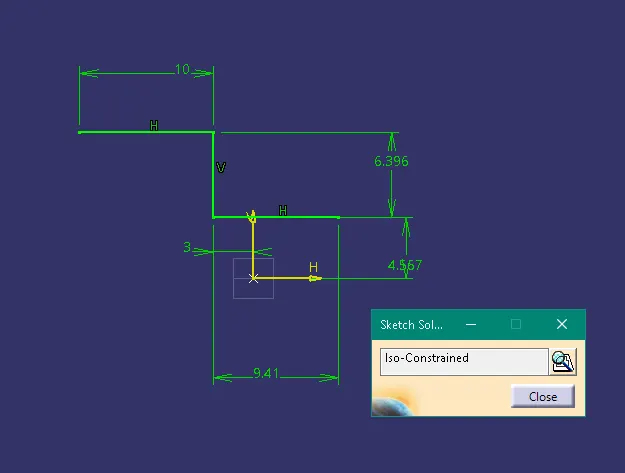
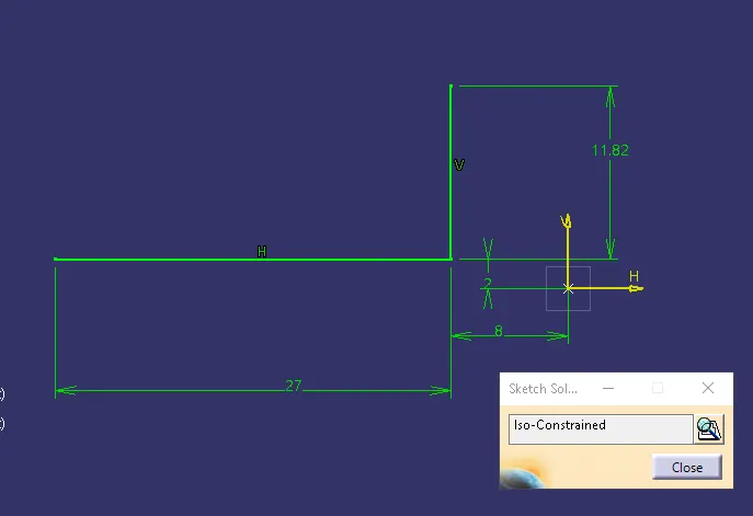
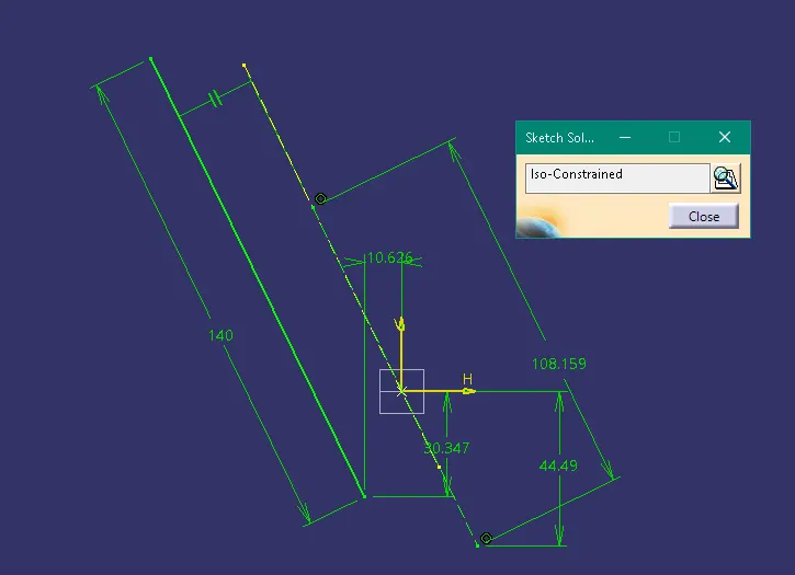
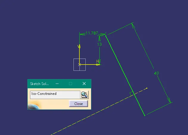
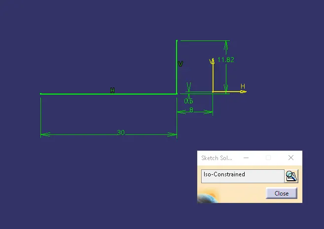
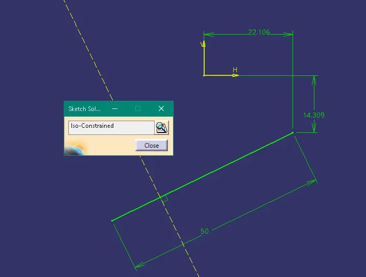
- Sketches for flange creation :
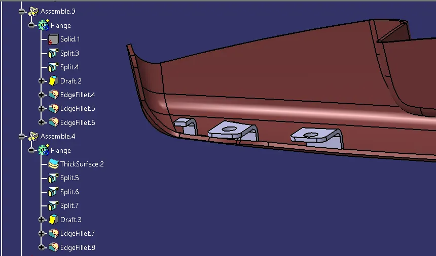
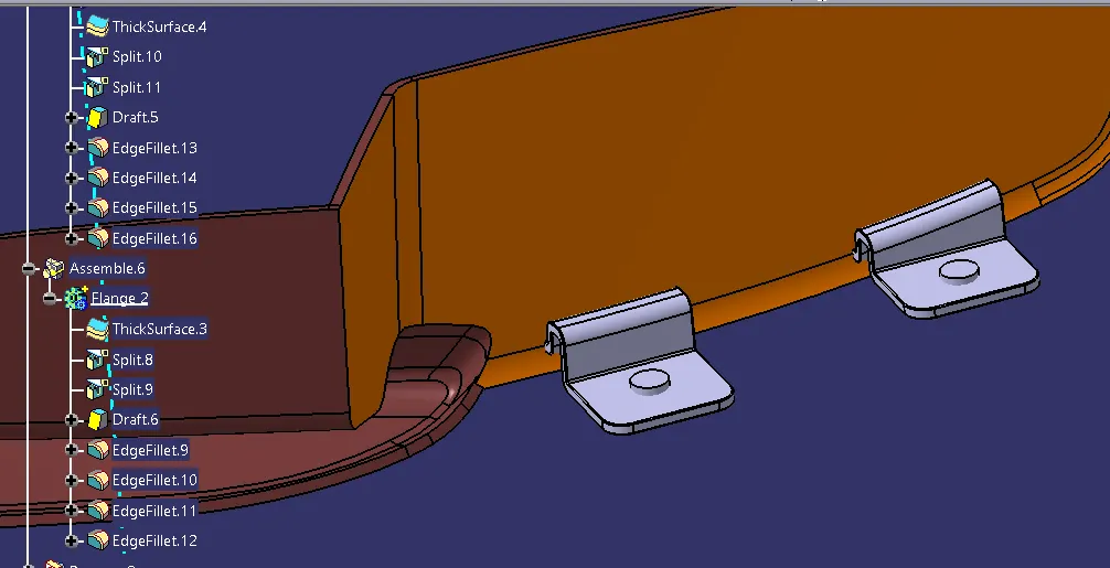
Thicken surface to create the Flange :
- Insert a new body and define that as a working object.
- Jump into the part design and select the thicken surface.
- And select the trim to give a 2.5mm to the upper direction to thicken the surface.
- Also offset the surfaces on the thicken part to split the flange for required length.
- Then use the split command to split the part.
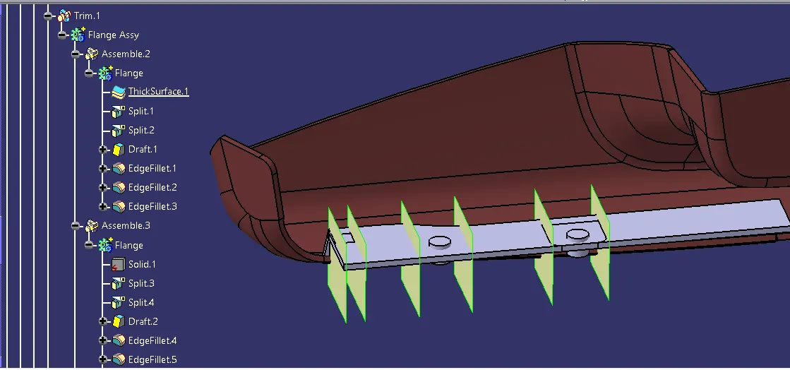
- And draft the flange faces with side core axis at 0.5deg.
- Finally give a fillet to the edges.
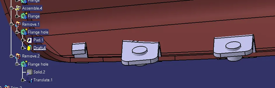
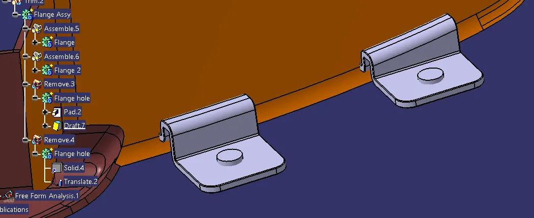
Flange hole creation :
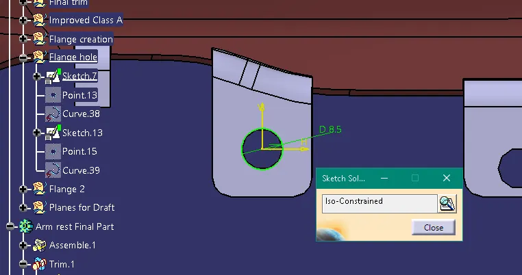
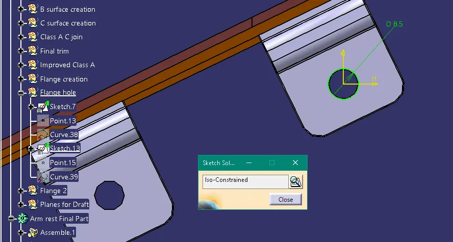
- Create a sketch for the flange hole.
- Insert a body and define a working object.
- Use the pad command to pad the sketch.
- Also give a draft to the outer face at o.5deg.
- Then use the paste special result with link to create a duplicate of the hole pad.
- And translate to the another flange.
Final flange creation :
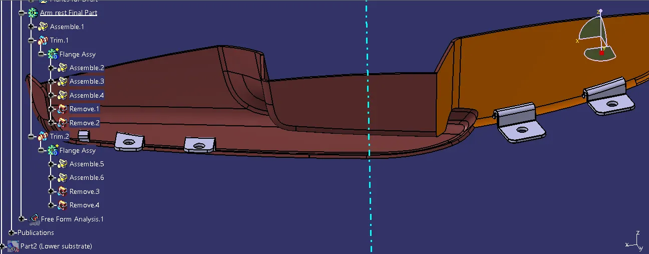
- Insert a new body then assemble all the flanges to that body.
- And remove the hole pad to that assembly body.
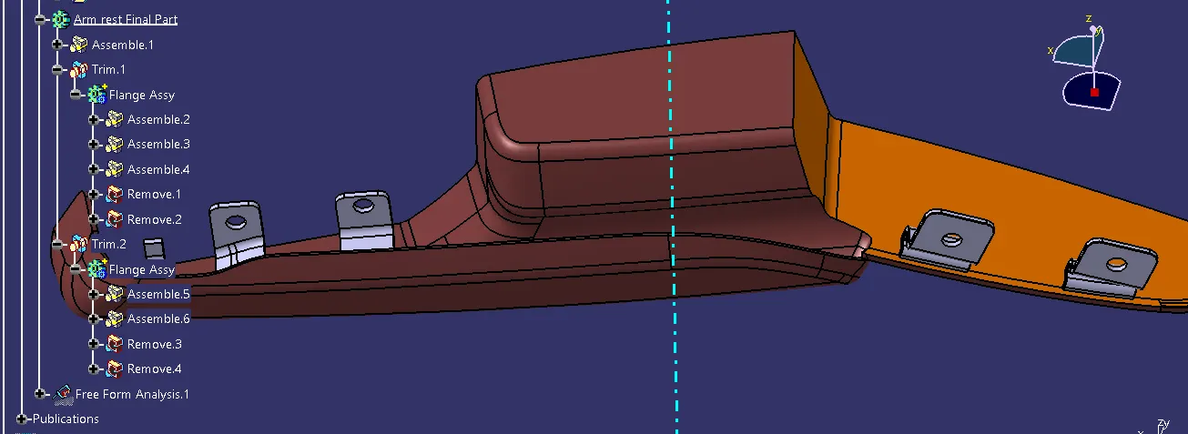
Union trim to the closed part :
- Use the union trim of the flange assembly to the closed part.
Flange creation in map pocket :
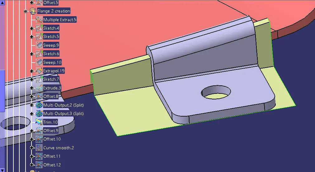
- First multiple extract the class C surface edge.
- Create a plane on that required area by using three point of master section.
- Also create a point on that center of the plane.
- Create a sketch with use the master section curves as a referance 3d object for flange 2.
- Use the sweep explicit with referance surface.
- Give profile is a sketch and guide curve as a multiple extract edge.
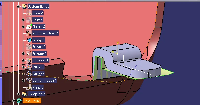
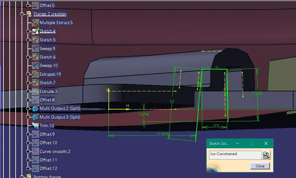
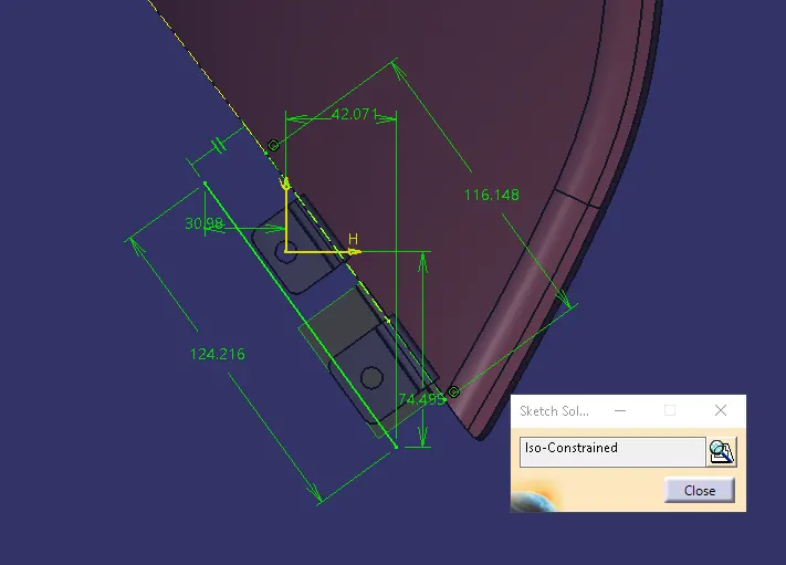
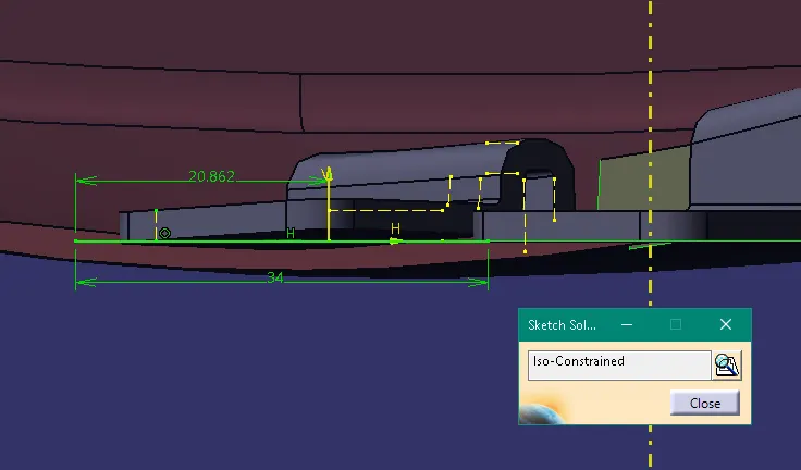
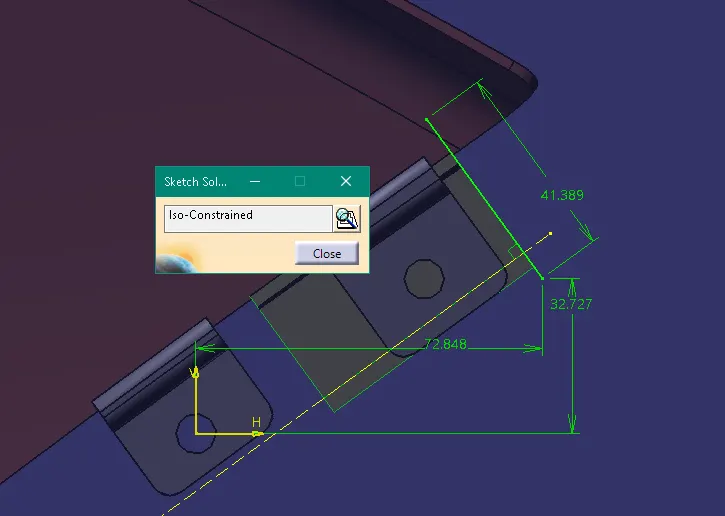
- And create another sketch for the flange 2 and bottom flange.
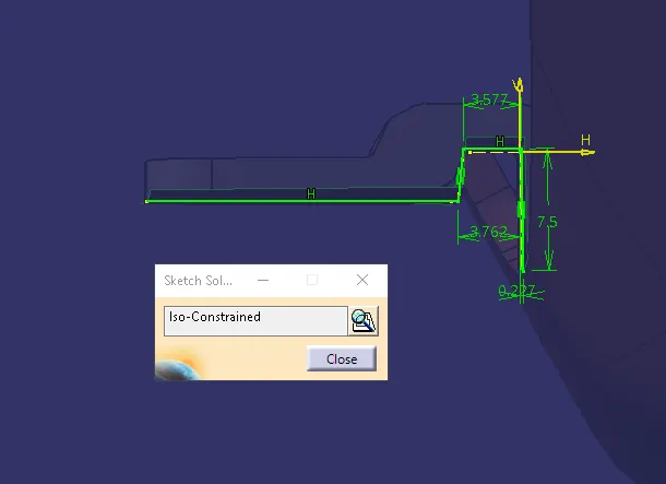
- I create the first flange by closed surface. So I create the sketch for that method.
Sketches for creating the Flanges :
Thicken the surface to make a flange :
- Insert a separate body for the separate flange.
- Use the closed surface for the first flange and use the thicken surface for the other two flanges.
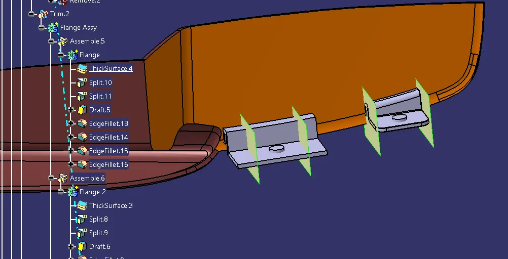
- Then offset the vertical surfaces for split the flange for the required length.
- And use the split command to split the flanges.
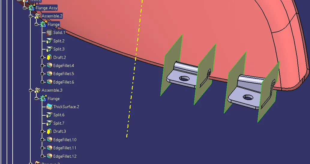
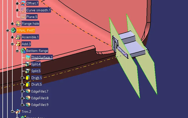
- And give the draft for the flange faces with 0.5deg.
- Finally fillet the edges for suitable.
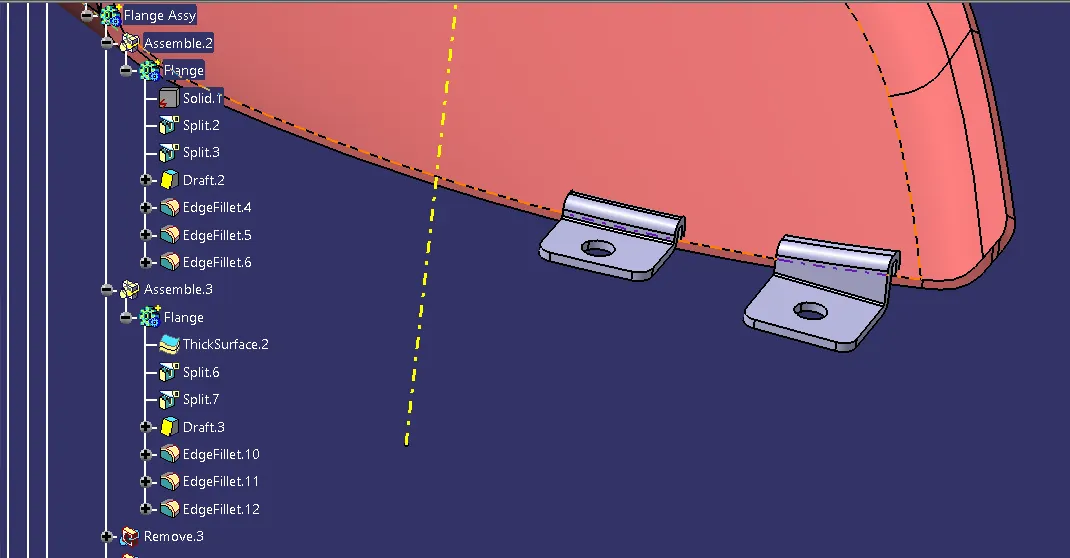
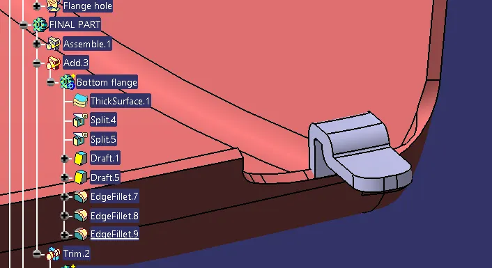
Flange hole creation :
- Create a sketch for the flange hole.
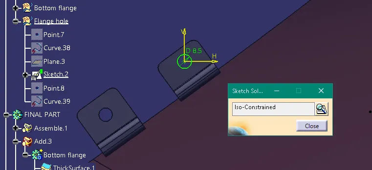
- Insert a new body and define as a working object.
- Use the pad command to pad the sketch for required height.
- Then give the draft of 0.5deg for the pad.
- And use the paste special result with link to duplicate the pad.
- Use the translate command to move wherever we want.
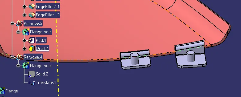
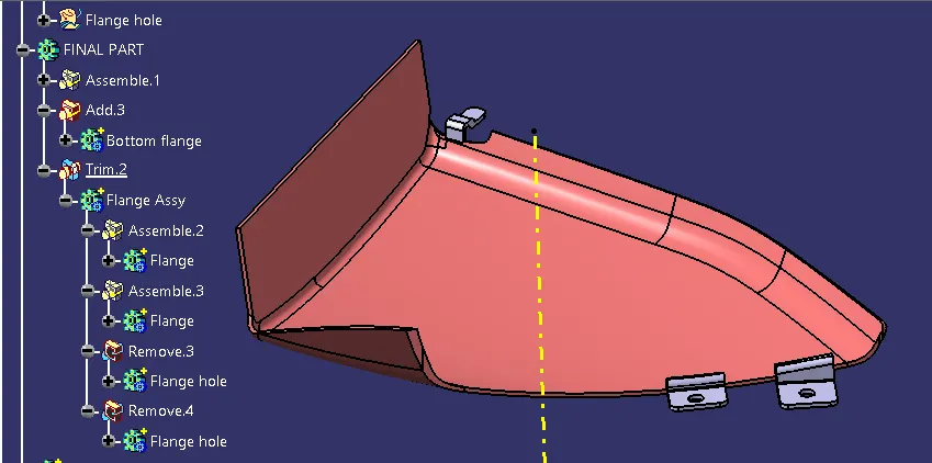
- Insert a new body to assemble the flanges to that body.
- Use remove command to remove the hole pad in the flanges to create flange holes.
- Finally union trim the flange assembly to the closed part to make a complete map pocket part.
Flange creation in bottle holder :
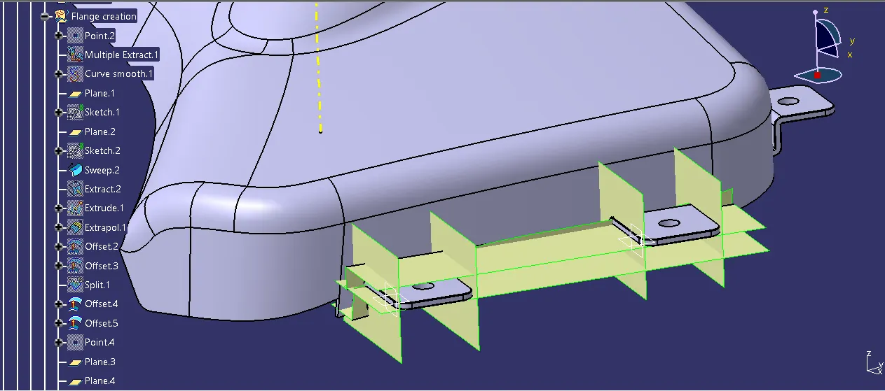
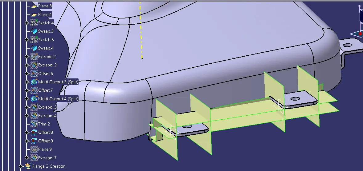
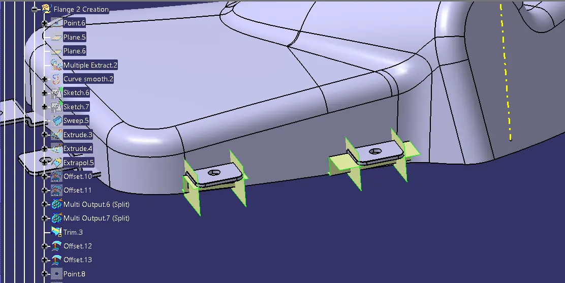
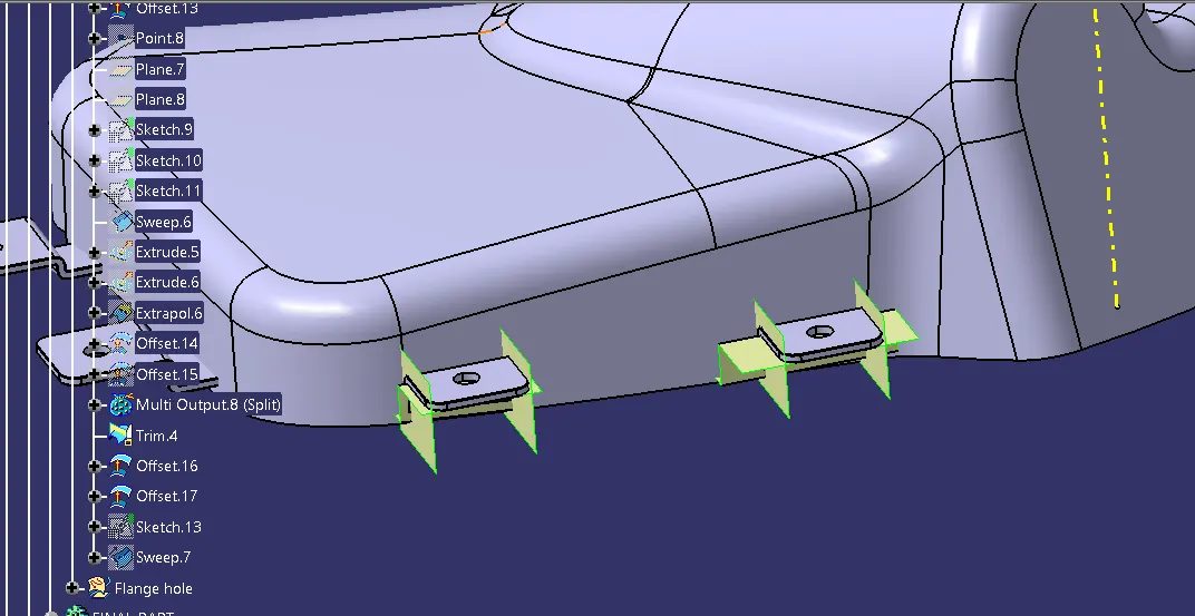
- First create a new geometricalset and multiple extract the class C surface edge.
- Then create a separate sketches for the separate flange.
- Use the sweep profile explicit sweep with referance surface.
- Give a profile as a one sketch and the guide curve as a another harizontal sketch to create a sweep.
- Then create a line in a sketch perpandicular to the C surface edge.
- And extrude that to create a surface for split the thicken surface.
Thicken surface of flange:
- Insert the new body for separate flanges to define as a working object.
- And jump into the part design.
- Select the thicken surface and select the sketch for the one flange then select the trim for the another flange.
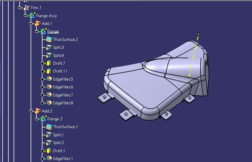
- Then use the offset surface to split the side limits of the flange.
- And give a 0.5deg draft for the flange faces.
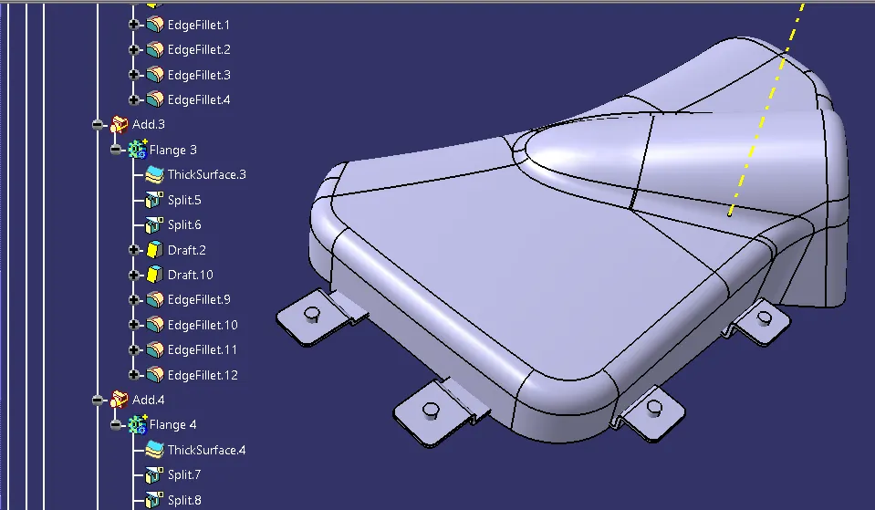
- And give the fillets over the edges of flange.
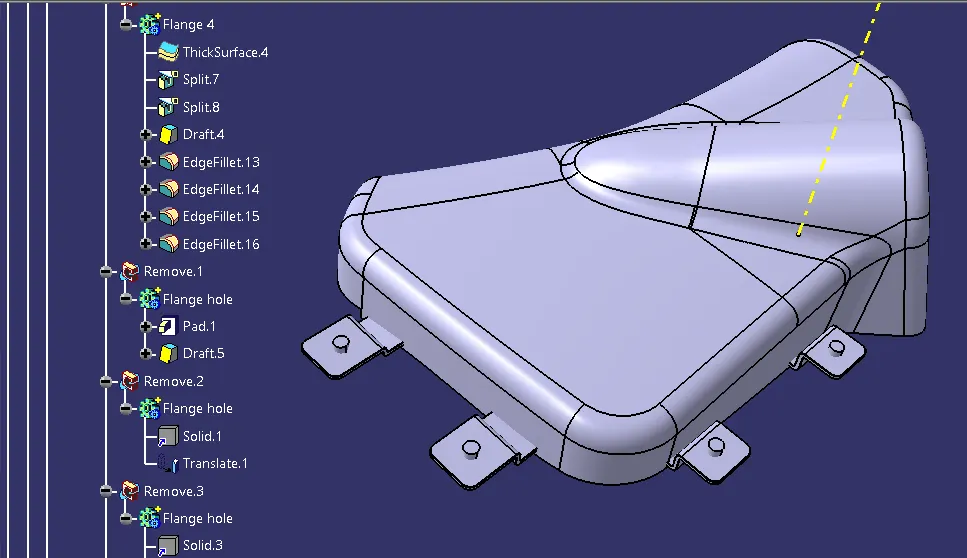
Flange hole creation :
- Create a sketch for a flange hole.
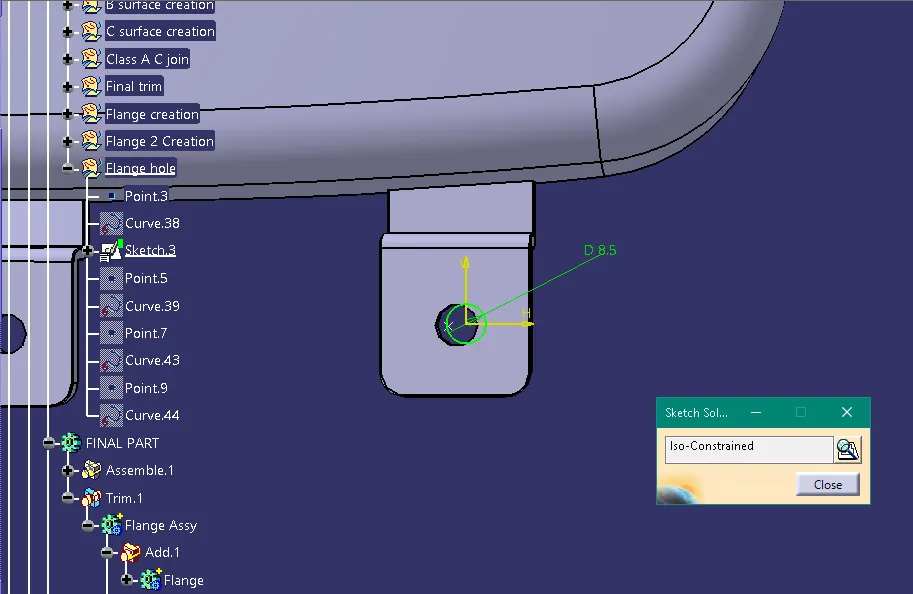
- Insert a new body and pad the sketch for the required hight.
- Then give a draft for the outer surface at 0.5deg.
- And use the paste special result with link to make a duplicate of the pad.
- Translate the pads wherever we want.
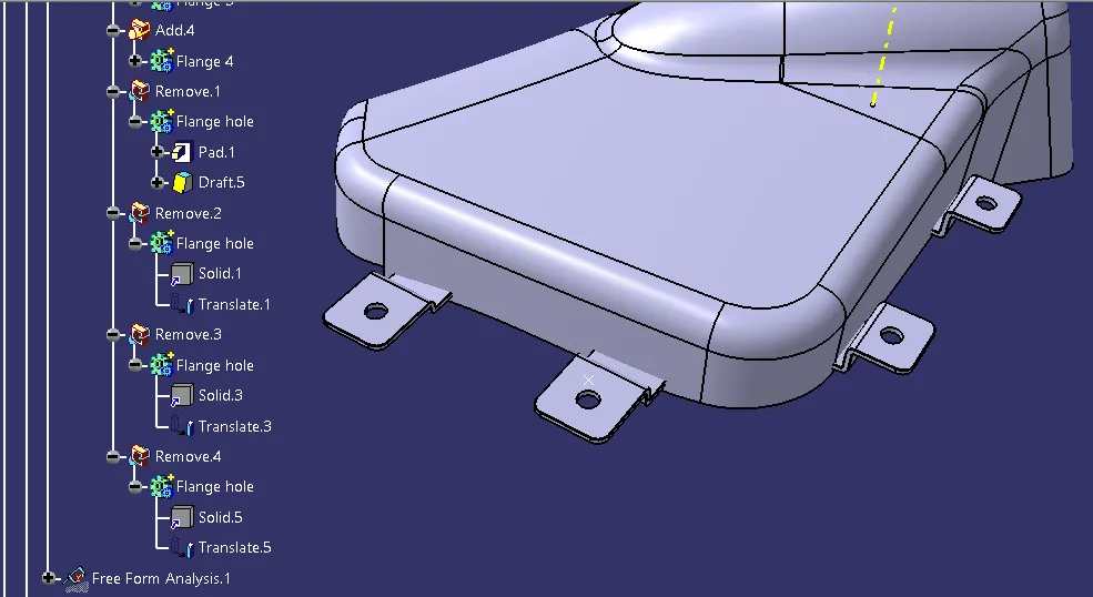
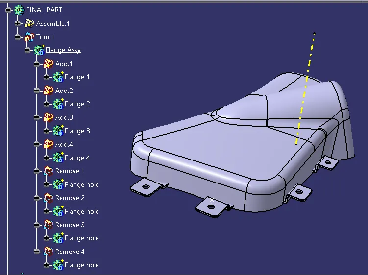
Union trim to the closed part :
- Insert a another body and assemble the flanges in it.
- And remove the flange hole pad to the flange assembly.
- Finally union trim the flange assembly to the closed part to get the final bottle holder part.
Heatstakes creation in Lower substrate :
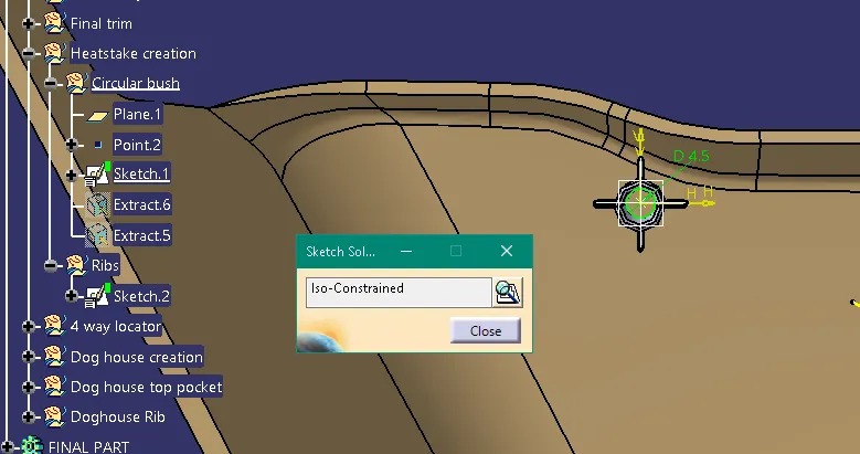
- First I create a point by mid point of the flange hole master section.
- And create a plane over the point.
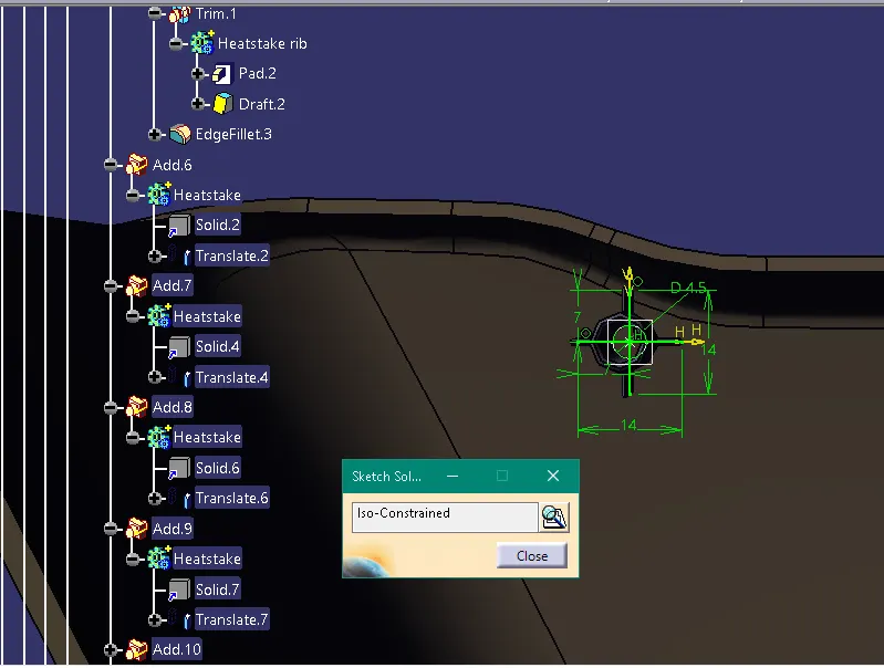
- Then I create a heatstake circular portion.
- I measure the heatstake diameter in the master section.
- And create the sketch for the heatstake circle.
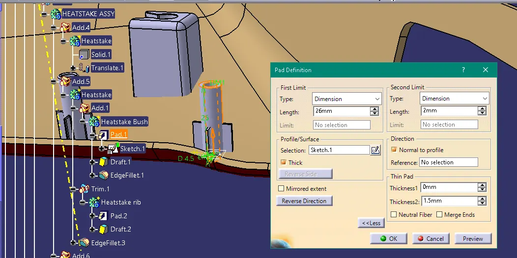
- Insert a new body and define as a working object.
- Create a pad using sketch for required hight.
- And draft the inside and outside faces at 0.5deg.
- Then give the fillet to the edge.
- And create a sketch for heatstake rib.
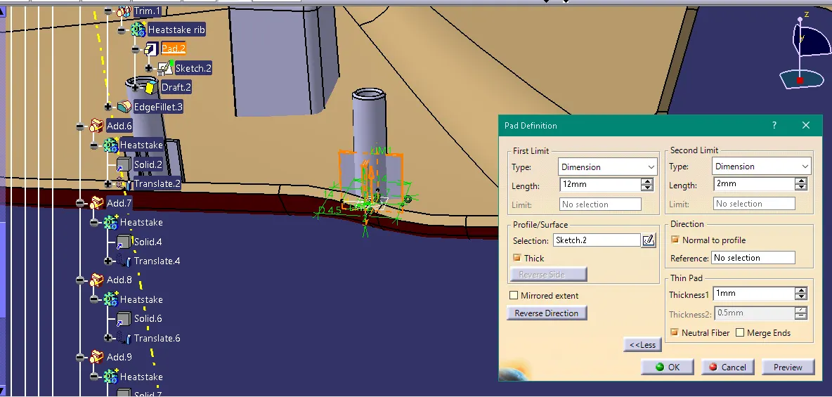
- Insert a body and create a pad by nutral fiber with required hight.
- Then draft the rib faces with tooling axis at 0.5deg.
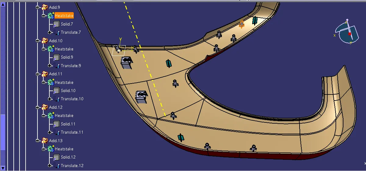
- Insert a new body and add the bush and union trim to the bush.
- Then use the paste special result with link to duplicate the heatstake.
- And translate the heatstakes for required areas.
- Insert a another body and add the all heatstake to that heatstake assembly.
- Then union trim to the closed part.
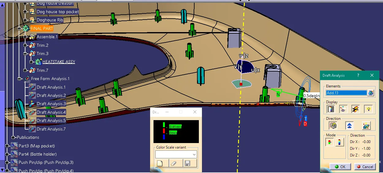
Draft analysis for heatstake assembly :
- Change the view to customize view and select material then give ok.
- Click the compass then drag it to place on the tooling axis.
4 way Locator creation in lower substrate :
- Extract the surface where the locator will fix.
- Then create a point on a surface.
- And create a plane on the point.
- Create a sketch for 4 way locator with respect to the point and the plane.
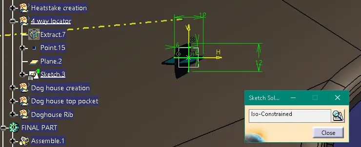
- Insert a new body and define as a working object.
- Then jump into the part design.
- Pad the sketch for required hight.
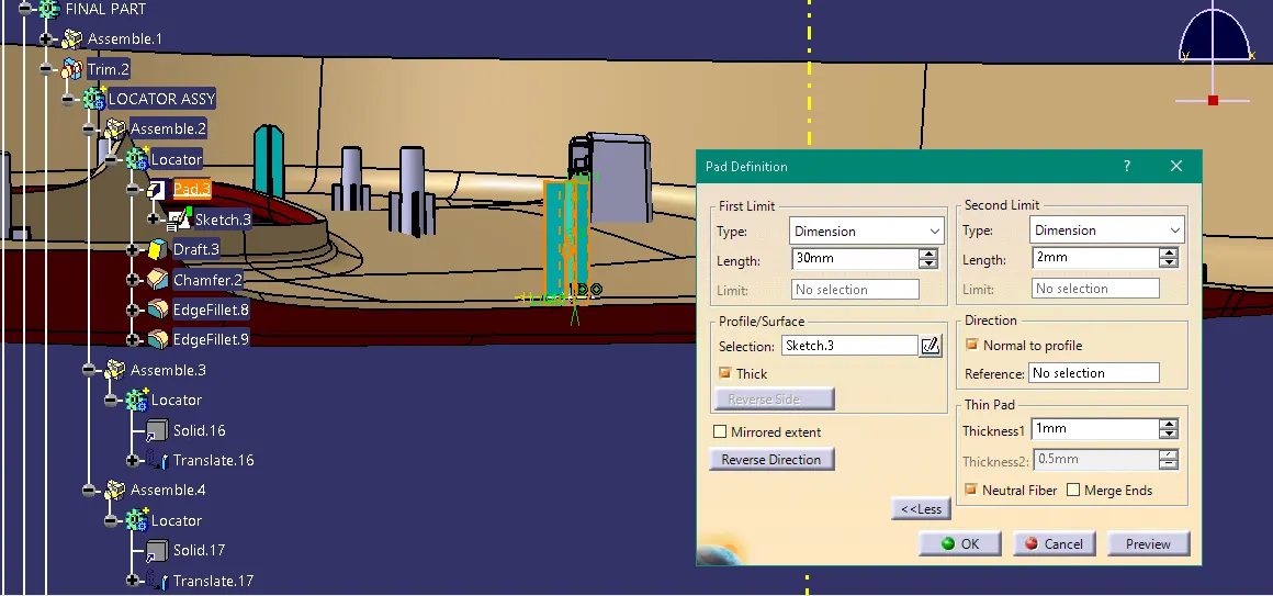
- And give the draft for locator at 0.5deg.
- Then give the entry chamfer 3mm.
- Give the fillet to the edges.
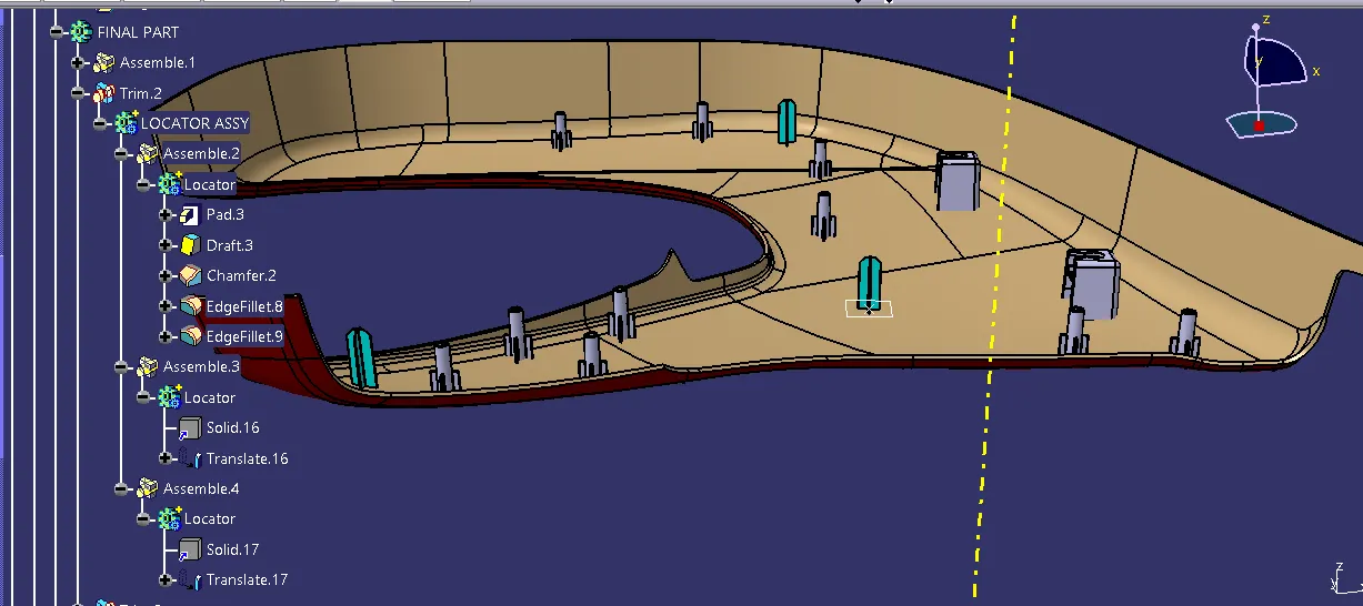
- And use the paste special result with link to duplicate the locator.
- Then use translate to move forther we want.
- Insert a body to assemble the locator.
- Finally union trim the locator assembly to the final part to get the final component.
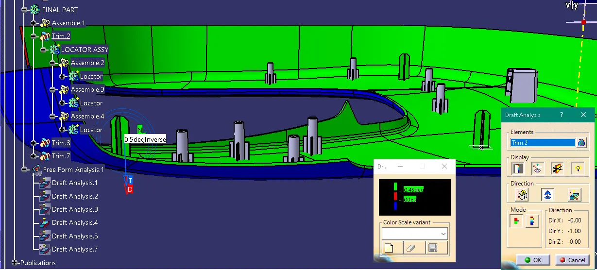
Draft analysis for the Locator :
- Change the view to customize view and enable material and click ok.
- Click the compass and place it on the tooling axis.
Doghouse wall creation in lower substrate :
- First extract the surface wherever the doghouse want.
- Create the point on the surface.
- And create a plane on the point.
- Then create a sketch for the doghouse.
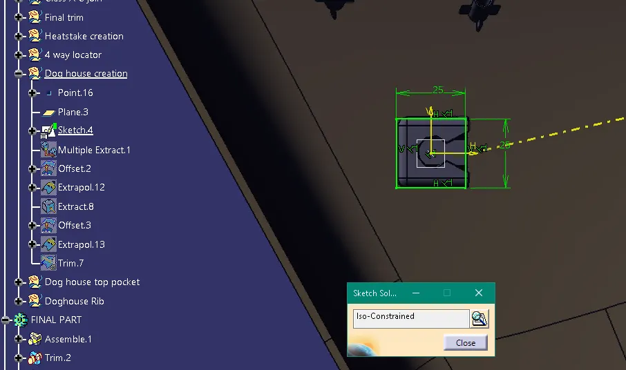
- Insert a body and define that as a working object.
- Jump into the part design then click the pad to select the sketch give required hight.
- Give the draft for four faces with tooling axis at 1.5 deg.
- Then use the shell command to select front and bottom face and give 2.5mm to make a proper doghouse wall.
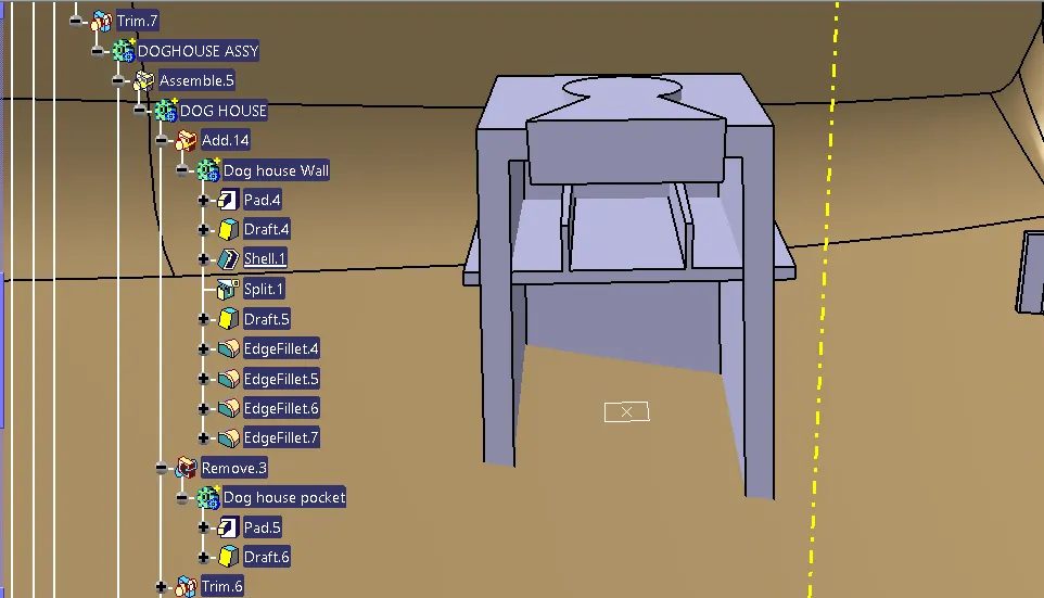
- Also draft the inner face of doghouse with side core axis at 0.5deg.
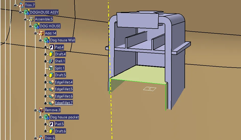
- And create a doghouse bottom clearance.
- Multiple extract the doghouse inner suface and offset that at 1mm.
- And extract and offset the doghouse bottom face at required hight.
- Then trim them to get the suface.
- Use that surface to split the doghouse.
- Also draft the cutted area at 0.5 deg.
- Then fillet the edges.
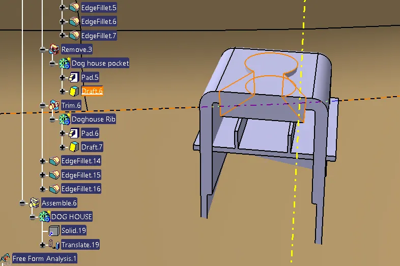
Doghouse top pocket creation :
- Create a sketch for the doghouse top pocket.
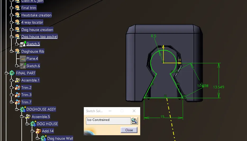
- Insert a body and pad the sketch for required hight.
- And give a draft to the side faces at 1.5deg.
Doghouse rib creation :
- Create a plane on the point.
- And create the sketch for the rib.
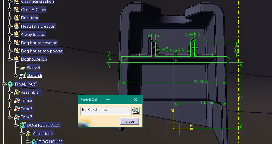
- Insert a body and pad the sketch.
- And draft the rib faces with side core axis with 0.5deg.
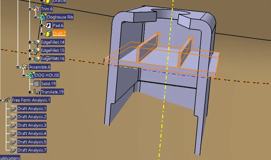
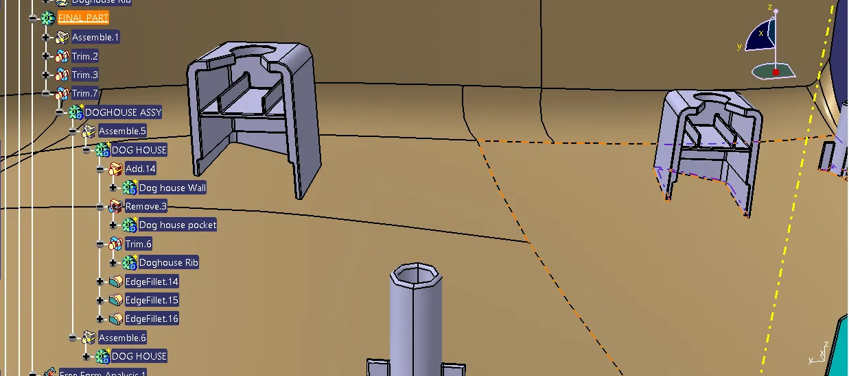
- Then insert a new body and define it as a working object.
- Add the doghouse wall to it.
- And use remove to cut the top pocket.
- Use union trim to trim the rib.
- Finally fillet the edges.
- Then use paste special result with link to duplicate the doghouse.
- And translate the doghouse wherever we want.
- Finally union trim the doghouse to the final part to get a final component.
Draft analysis for doghouse with main tooling axis :
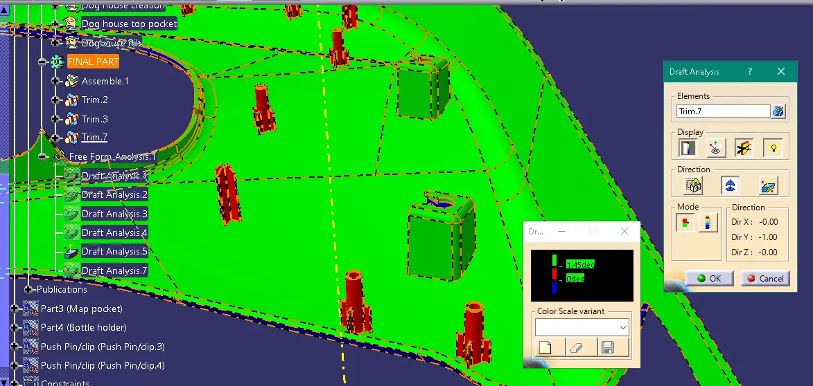
Draft analysis for doghouse with side core axis :
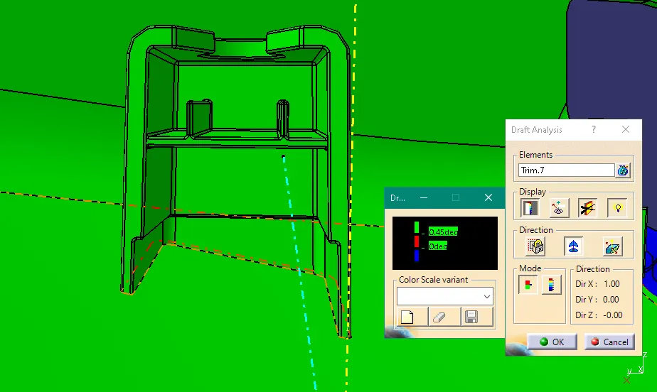
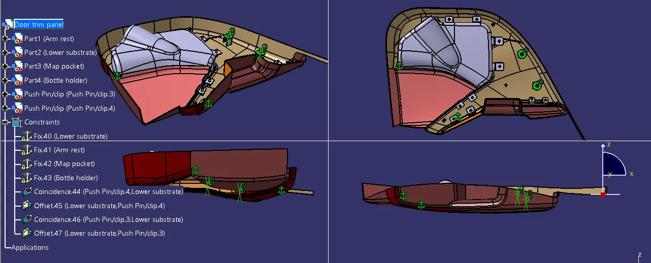
Door trim panel product constrains to fix the pushpins :
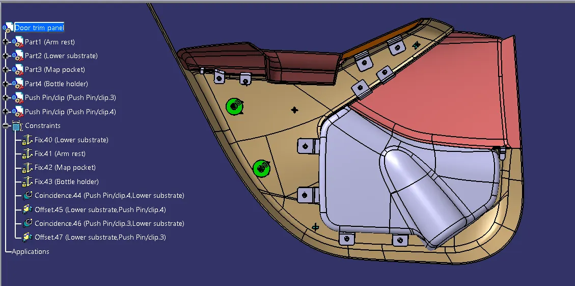
Draft analysis for Arm rest part :
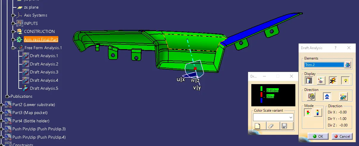
Draft analysis for Lower substrate part :
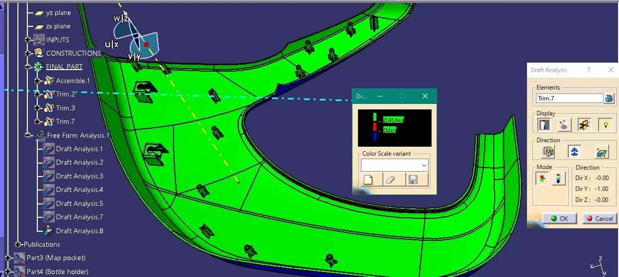
Draft analysis for Map pocket part :
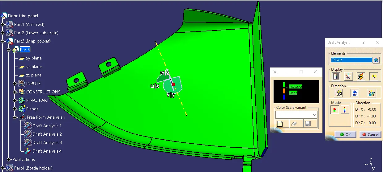
Draft analysis for Bottle holder :
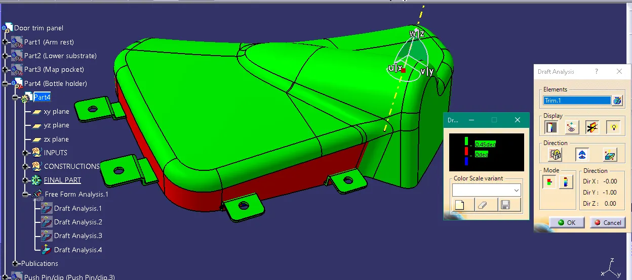
Front view, Top view, Side view and Isometric view of Door panel :
Conclusion :
I learn a lot of things while duing the final project. At last all the class A, class B, class C and engineering features are created as per the rule. And I use the publication for finding the things. All the area even wall thickness maintained.