Week 12- Final project
INPUT I RECEIVED :-
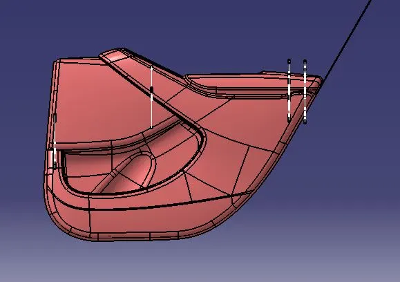
the input i received considering its orientation it is of rear right hand side door trim panel of vehicle.
CLASS A INPUTS:-
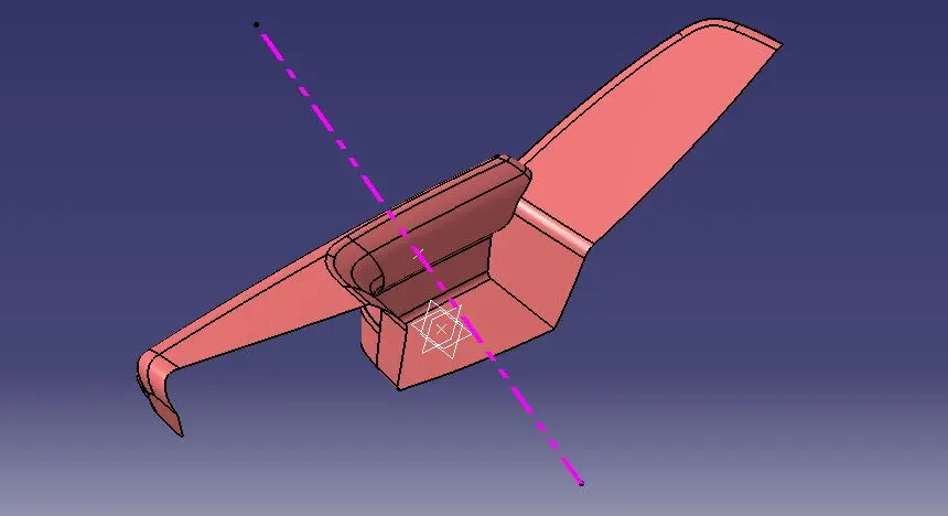
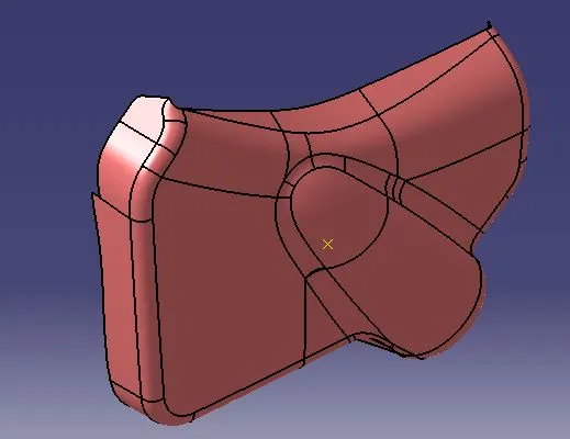
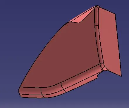
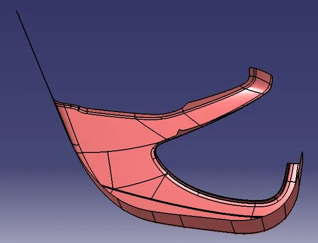
1.ARM REST
TOOLING AXIS & DRAFT ANALYSIS ON CLASS A :-
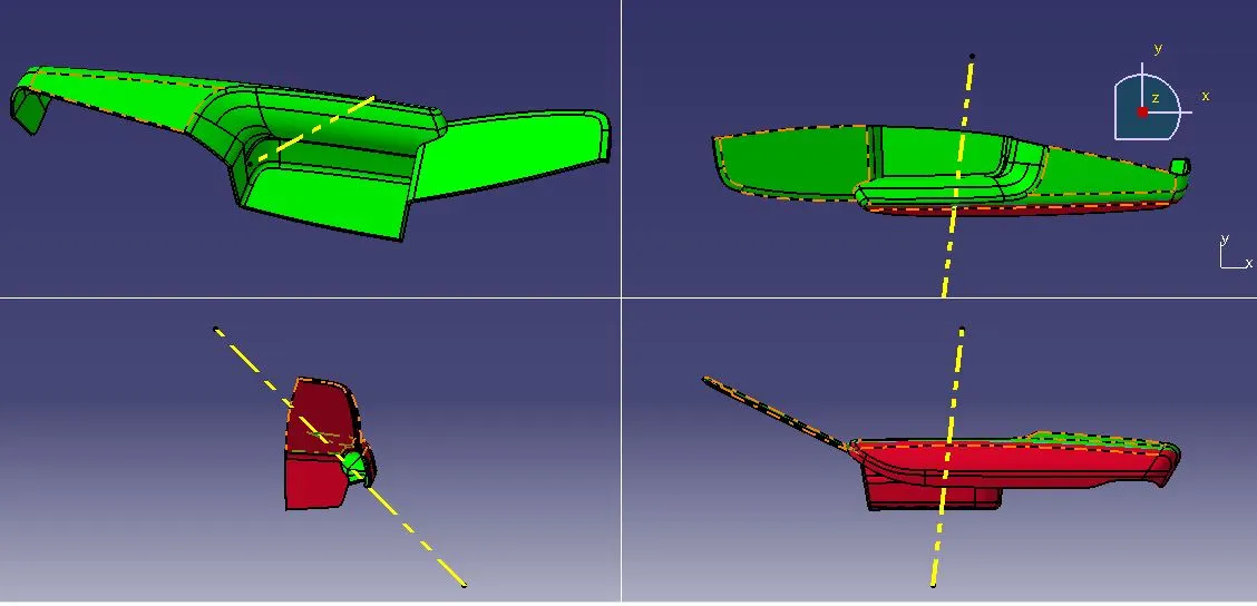
As the component is not being able to ejected properly in single tooling direction so we have to consider side core axis for this part & i created tooling axis for this by following further mentioned steps:-
select measure inertia tool > select surface > click on create geometry (the window that open up shown below )>click on center of gravity. as it will create point with geometrical set by default.
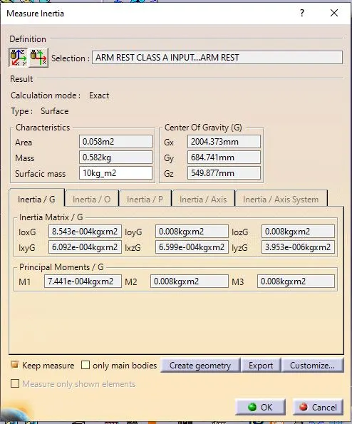
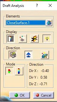
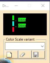
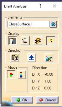
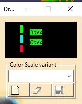
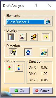
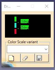
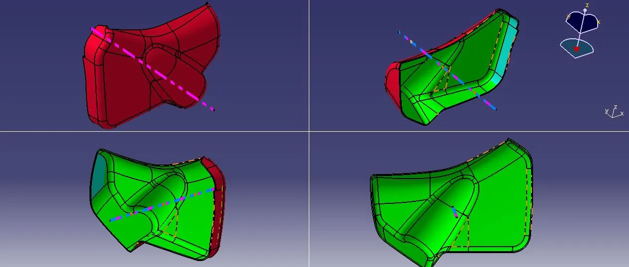
then i decide a direction among 3 where maximum projected area is seen considering that line and point i got through above process for draft analysis on surface,after doing that double click on head of compass an window named"parameter for compass manipulation"opens up and adjusted the degree at which it is clearing max. portions,then locked the compass orientation by clicking on compass selecting "lock current orientation"and again make a line through point and direction option considering compass direction the result of which is as follows:-
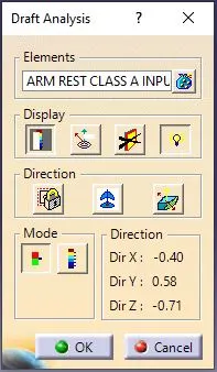
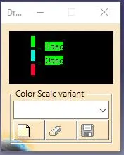
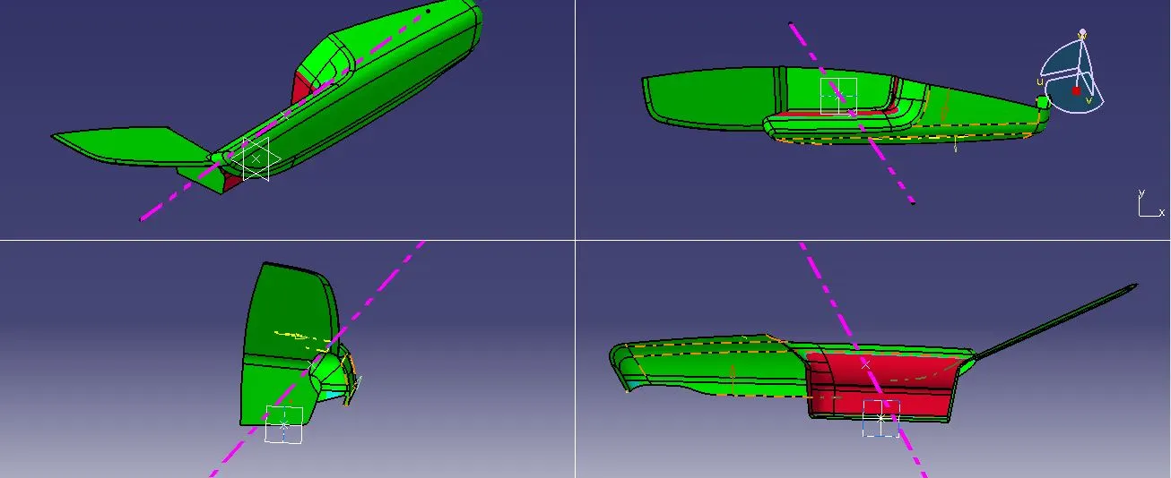
now for remaining portion i opted to go with side core axis and this is created by extracting specific surfaces following same method for creating tooling axis as mentioned above and the outcomes of it are displayed below:-
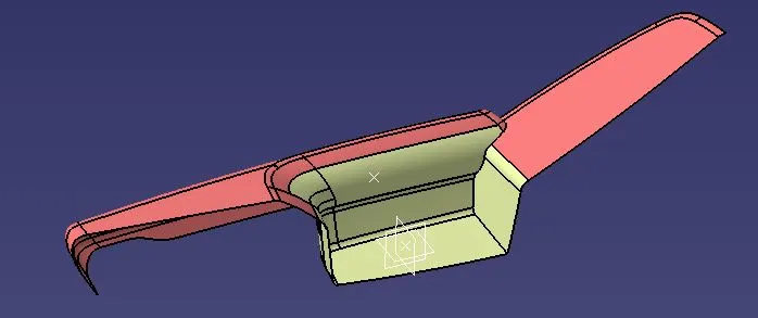
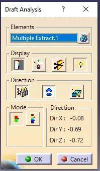
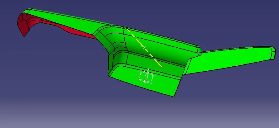
2.LOWER SUBSTRATE
TOOLING AXIS & DRAFT ANALYSIS ON CLASS A :-
tooling axis is created by considering extreme position lines and bisecting through a point as shown below
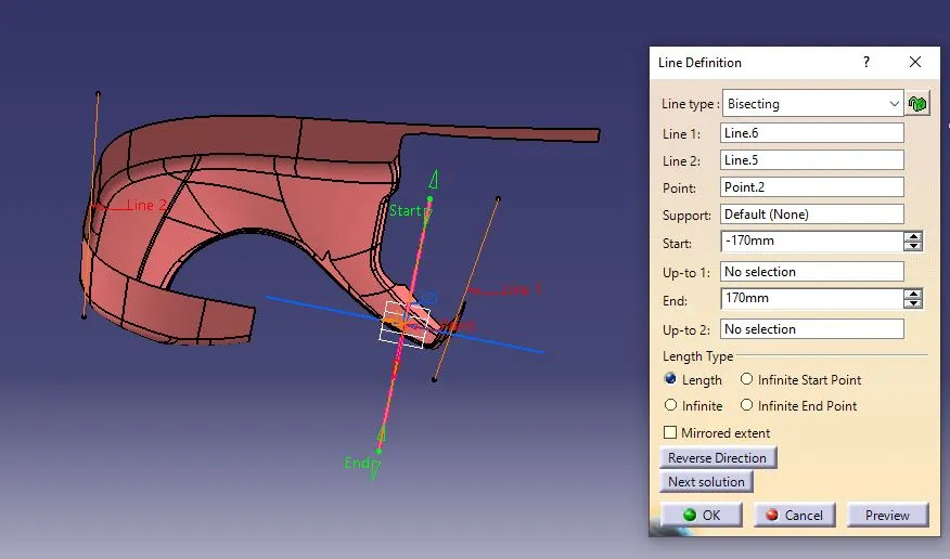
draft analysis result on it are shown below :-
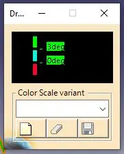
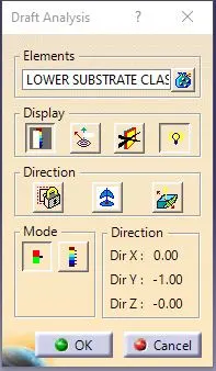
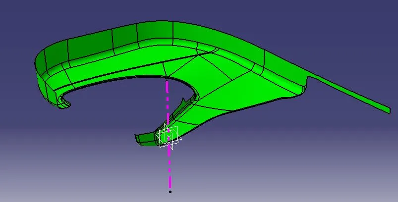
3.MAP POCKET
TOOLING AXIS & DRAFT ANALYSIS ON CLASS A :-
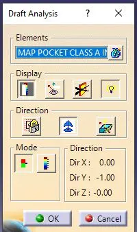
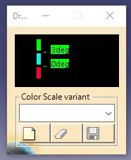
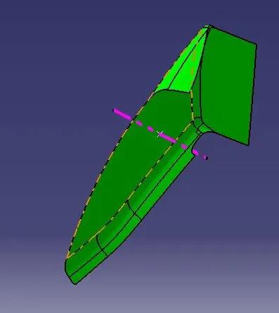
as the surface was quiet simple so i generated tooling axis by considering point as C.G. & direction with the trial & error with compass.
4.BOTTLE HOLDER
TOOLING AXIS & DRAFT ANALYSIS ON CLASS A :-
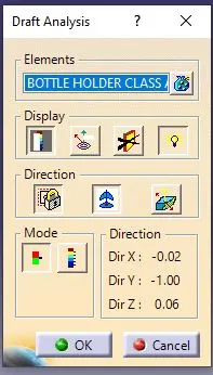
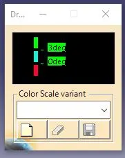
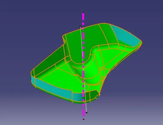
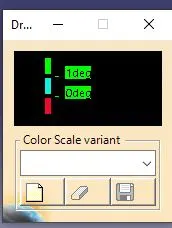
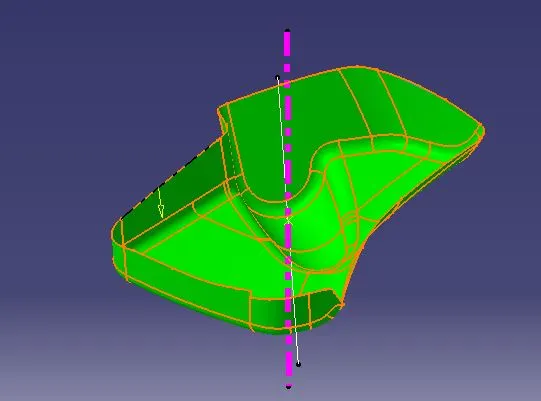
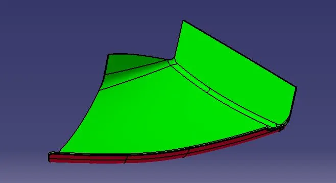
tooling axis creation is done by following same method with C.G. as point & direction with adjusting the compass.draft analysis result on it are shown below :
the surface was not getting clear for 3 deg but it is clearing for 1 deg.
CREATION OF CLASS B ,CLASS C ,CLASS A&C JOIN, FINAL TRIM:-
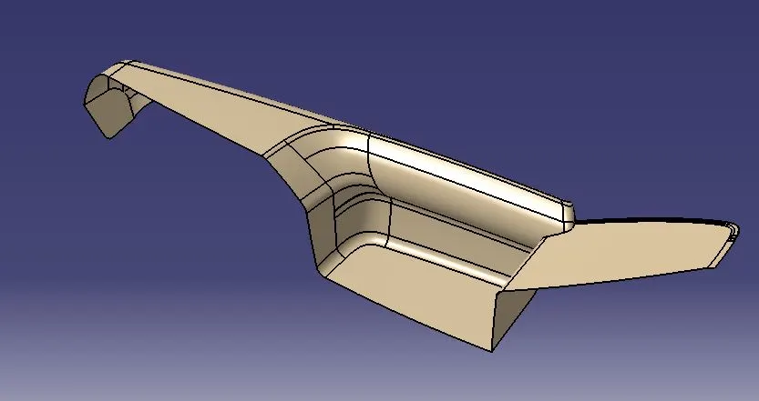
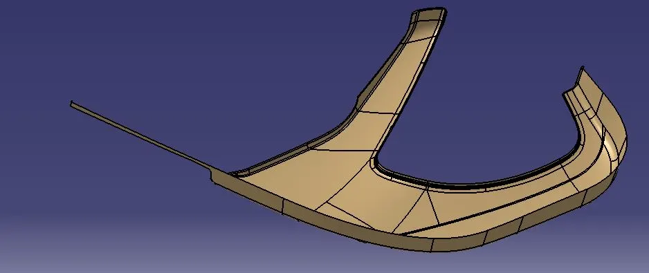
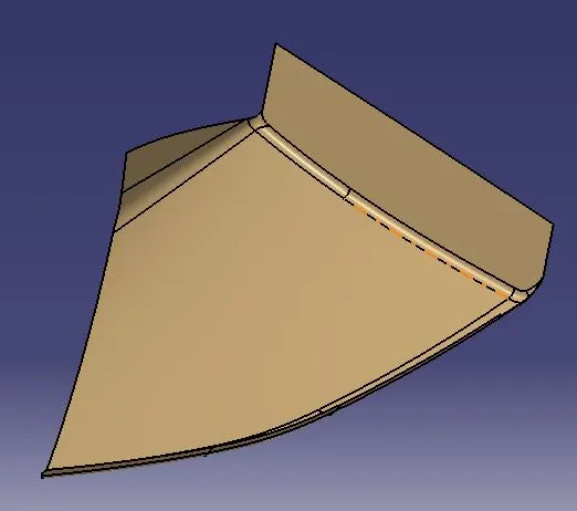
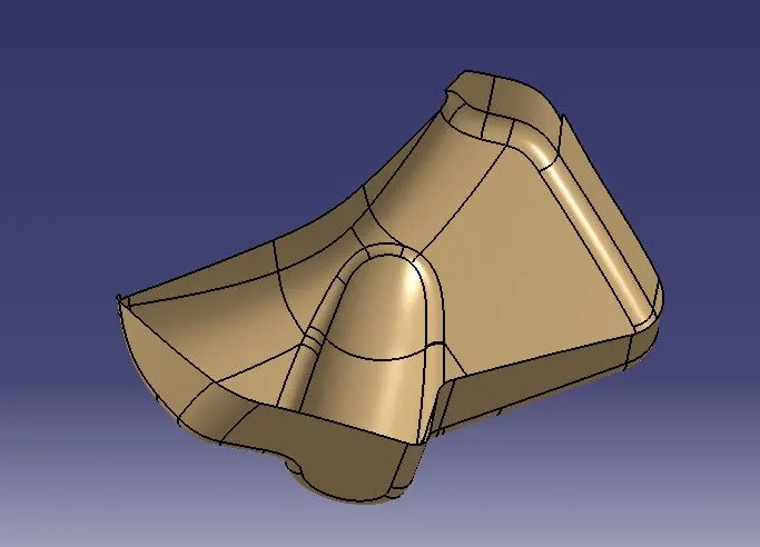
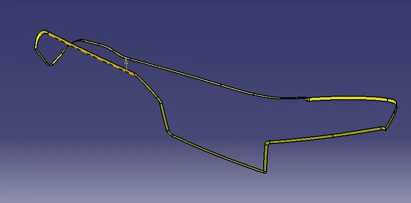
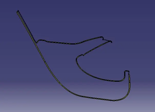
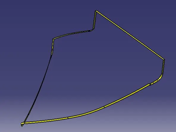
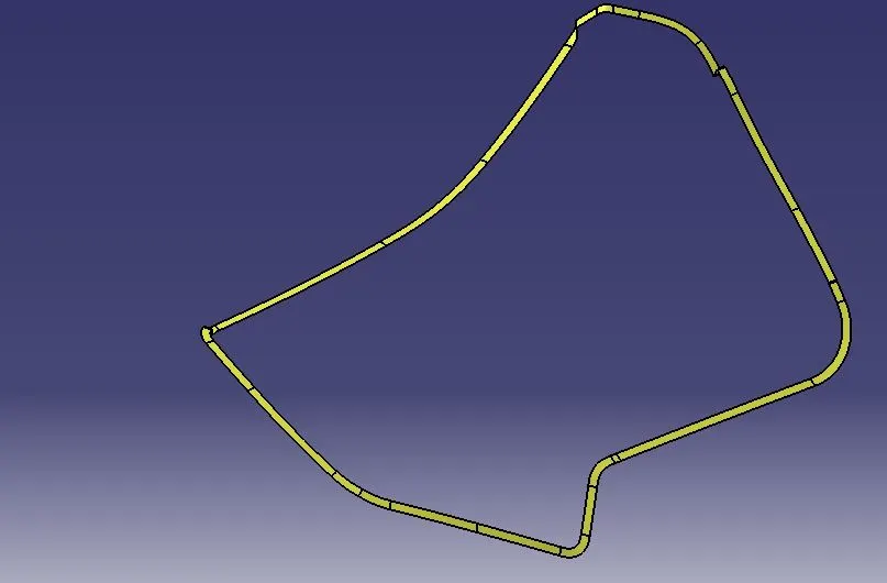
For creation of class B surface offset command is used,for creation of class c sweep,fill,multiple extract and trim,split & join is used to get final outcome.
the results are shown below:-
CLASS B SURFACE
CLASS C SURFACE
CLASS A & C JOIN
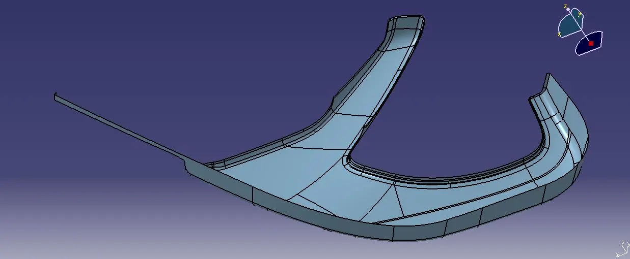
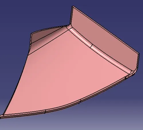
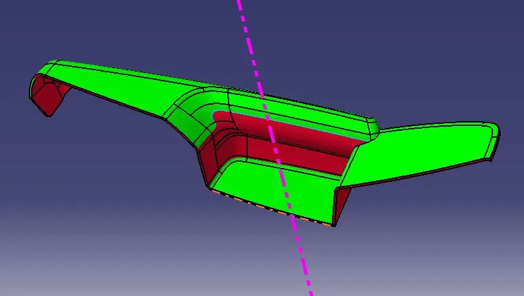
DRAFT ANALYSIS RESULT ON FINAL TRIMS
ARM REST
LOWER SUBSTRATE
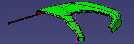
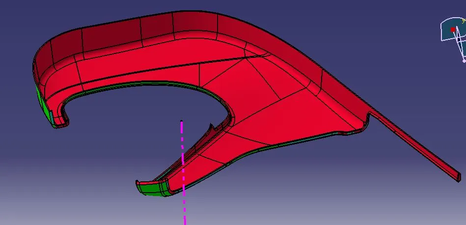
MAP POCKET
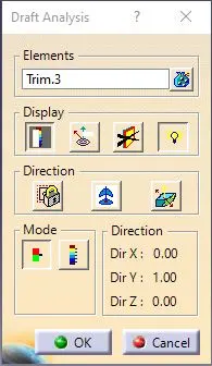
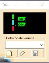
BOTTLE HOLDER
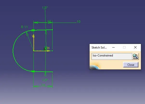
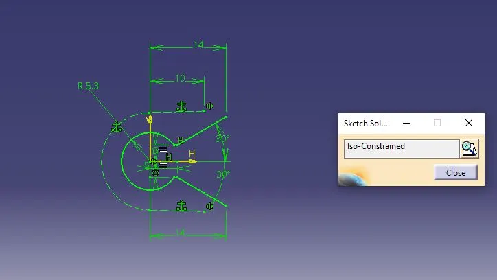
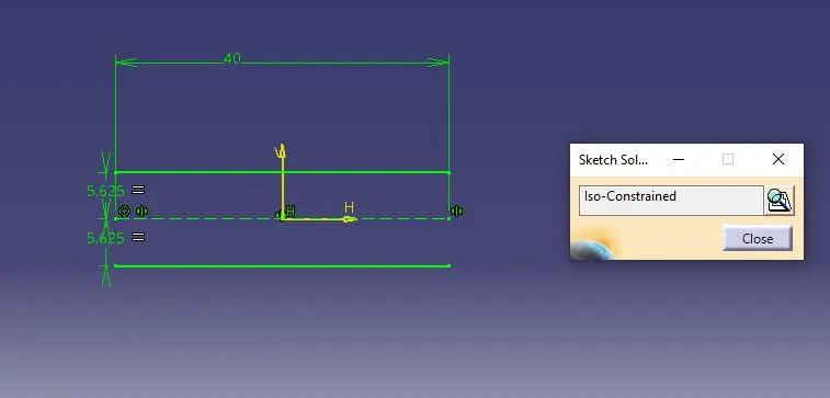
FOR attachment purpose we had to use heat stakes for part to part attaachment and doghouse in lower substrate.
what is heat staking & why to use it?
heat staking is a joining technology to join two or more parts together where atleast one is made of plastic. the process is used to melt and deform the plastic material using heat & force at a set process time.
De-forming the plastic is achieved by heating it above the glass transition temperature and apply pressure.after heating ,the materials are cooled down under pressure again to below the glass transition temperature.
Using heat staking can be a repeatable,economical and safe method to form a stud joining two pieces of plastic and other materials.
the big advantage of heat staking is that it is possible to use the base material to make such a connection.this doesn't require huge design changes and extra material,such as screws ,are not needed.
HOW I APPROCHED IN THIS PROJECT REGARDING POSITIONING OF ATTACHMENTS:-
- initially i started with lower substrate with the use of available mastersections finalised the dimensions of heat stakes.
- with the use of extract,boundary,parallel curves commands & multiple point option i plotted the points for heat stakes & doghouses considering positioning of other parts.
- then created the heat stakes & doghouse ,and translated & rotated them to points plotted respectively.
- after creating heat stakes & doghouses in lower substrate,flanges for locking are created in other parts taking references from mastersections.
- now after having flanges the heat stakes orientations are re-adjusted for proper alignment of holes.
- after this proper arrangements heat stakes & doghouses are joined with union trim command to lower substrate.
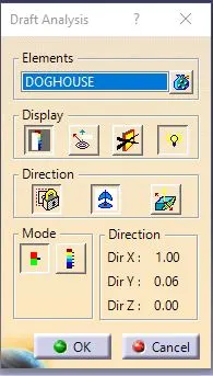
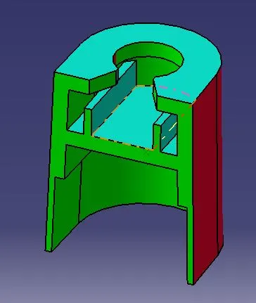
Few images related to doghouse creation are attached below:-

DRAFT ANALYSIS RESULTS ON FINAL CAD MODEL WITH FLANGES:-
ARM REST
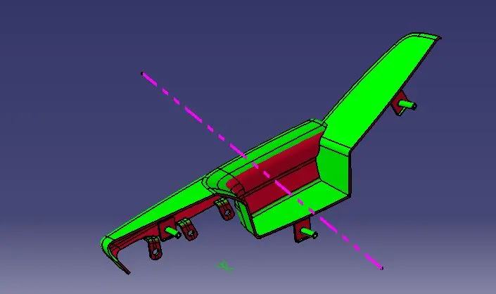
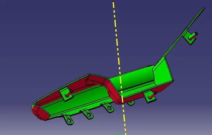
LOWER SUBSTRATE
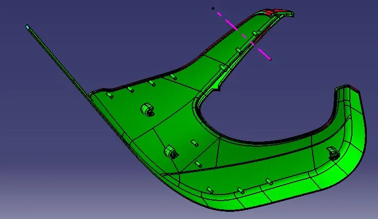
MAP POCKET
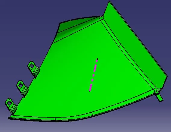
BOTTLE HOLDER
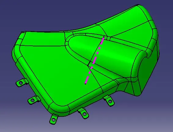
ISOMETRIC VIEW OF DOOR TRIM PANEL
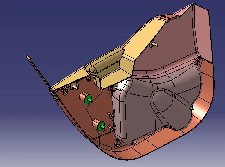
FRONT VIEW
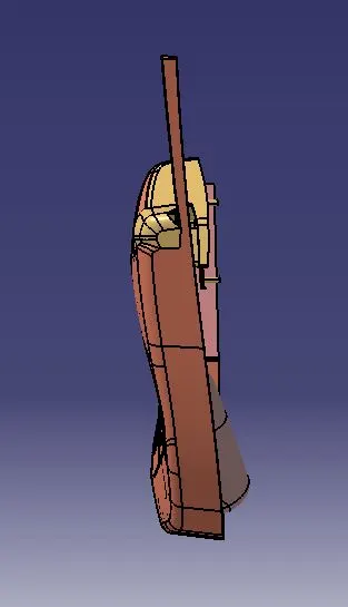
TOP VIEW
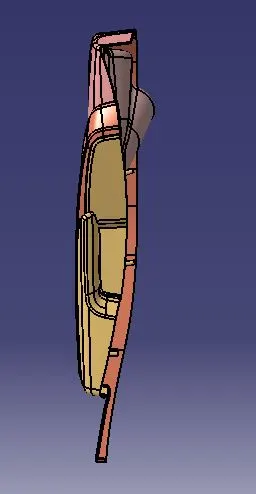
RENDERED IMAGE OF SIDE VIEW
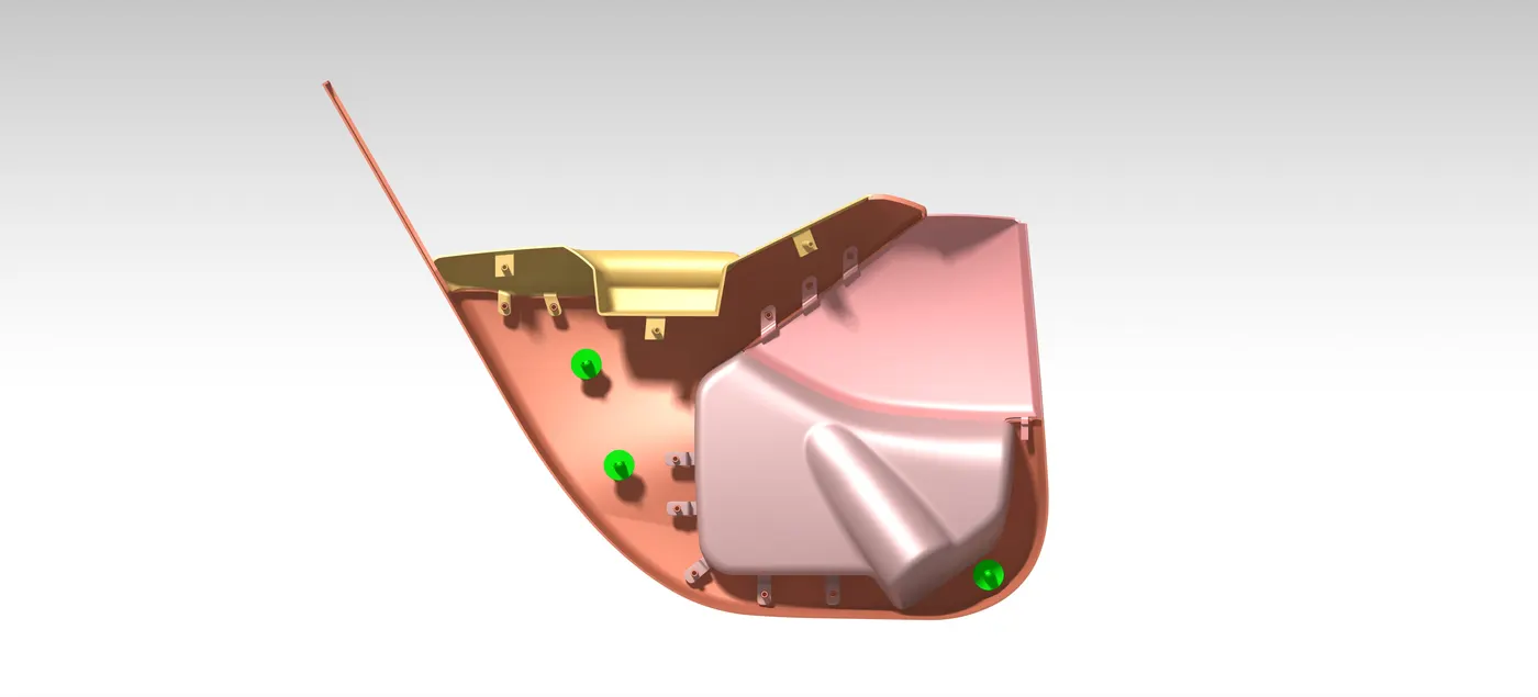
MATERIALS THAT TO BE USED FOR ABOVE PARTS
Considering the physical properties needed as per the working environment the likely materials that can be use is either NYLON or ABS as base material,the grade and make might vary from availability from firm to firm with their own criteria.
KEY LEARNINGS :-
- learned about how to handle the input of class A assembly .CATPART file & convert it into .CAT PRODUCT & vice-versa.
- learned about how to effectively use mastersections to get required output cad model.
- learned about what kind of strategy need to follow while creating attachments for interlocking purpose.
- During creation of models how to solve errors like topological errors , split/ trim operator errors etc.