Week 12- Final project
Week 12- Final project
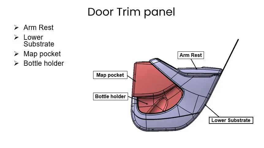
Door Trim panel
Aim:
Create a product file by separating the given Class A data into individual parts. Define the tooling direction for each part and generate solid bodies by creating proper Class B and Class C surfaces. Follow the master section to design flanges and engineering features. Finally, add additional engineering features, such as dog houses and heat stakes, for the final joining operations.
Door Trim panel:
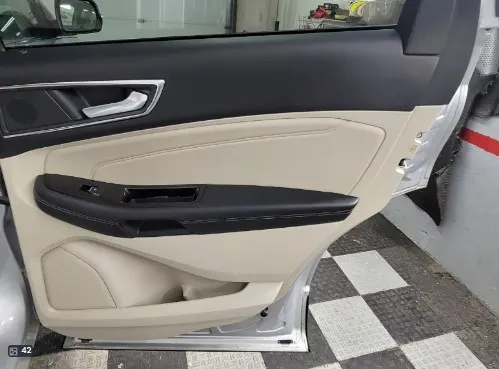
Door panels act as a bridge between the car's interior and the door's mechanics, as well as between occupants and the door itself. They must meet stringent safety, aesthetic, and functional requirements while matching the dashboard and pillar materials. Historically, door panels evolved from basic systems with latches and manual mechanisms to complex assemblies featuring electronic windows, central locking, and speakers. Modern panels generally include a foamed core covered in textiles or plastics. Plastics are fundamental to the door trim’s design, providing versatility and cost-effectiveness in molding and manufacturing. Understanding the types of plastics used and their cost implications is crucial for effective design and production.
Class A Surface:
1. Class A Surface refers to the highest quality surface finish in automotive design, primarily focusing on the visible exterior and interior components of a vehicle. It represents the final, production-ready surface data, ensuring the utmost aesthetic appeal and surface smoothness. Achieving Class A status requires a deep understanding of automotive design and advanced surface modeling skills. This process involves not only shaping the vehicle’s primary surfaces but also perfecting details such as flanges and panel gaps, ensuring that the design intent is fully realized in the final manufactured product.
2. After separating the given Class A Surface into individual parts. Check the gap of class A Surface if there is gap we want to improve Class A Surface.
Tooling Axis:
The tooling axis, also known as the mold or die draw direction, is a crucial reference line used in the design and manufacturing of plastic components, particularly in injection molding. It represents the direction in which the mold opens and closes, allowing the part to be ejected from the mold without undercuts or interference. The tooling axis is typically aligned with the main direction of the part's features to ensure that all surfaces can be formed and released from the mold efficiently.
Insert Geometrical Set: Extract the base surface, create a central point on it, and identify a suitable axis direction for tooling clearance.
Create Axis System: Set up an axis system at the central point and create a position sketch using the ZY plane from this axis system.
Generate Y Tooling Axis: Use "Intersect 3D Objects" to create intersecting lines on the ZY plane. Create a bisecting line aligned with the desired Y-axis direction.
Create X Tooling Axis: Make a position sketch with the XZ plane and the central point. Use "Cut Section" to create an intersection line and align it to form the X tooling axis.
Define X Tooling Axis Angle: Draw a horizontal line from the origin, apply a 5-degree angle constraint, and bisect this line with the previously created X tooling axis line.
Determine Final Tooling Axis: Use the "Bisect" option to create a line between the X and Y tooling axes, and name this final line as the tooling axis. Publish it for use.
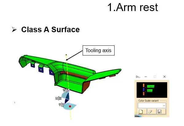
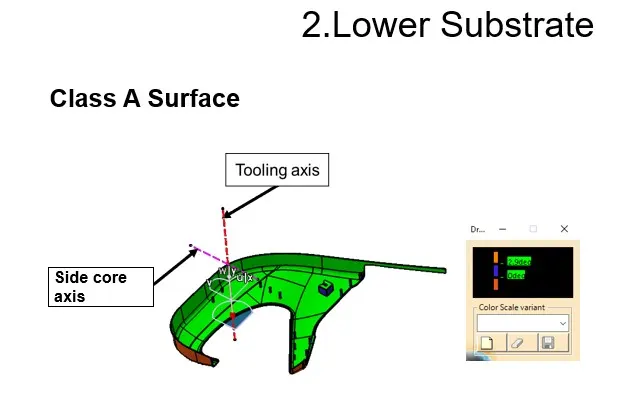
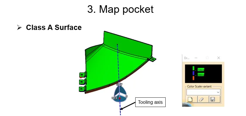
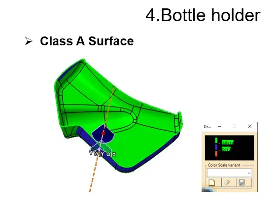
Class B Surface:
To create a Class B surface from Class A surfaces, first extract the Class A surfaces and untrim them to their full extent. Ensure proper intersections by using extrapolation as needed, then trim and offset the surfaces by 2.5 mm to achieve the desired thickness. Place the trimmed surfaces into a new geometrical set and name it accordingly. Apply fillets to the edges, adjusting the component thickness if necessary to maintain uniformity. Finally, review and refine the geometry to ensure all surfaces meet design specifications and requirements.
Class C Surface
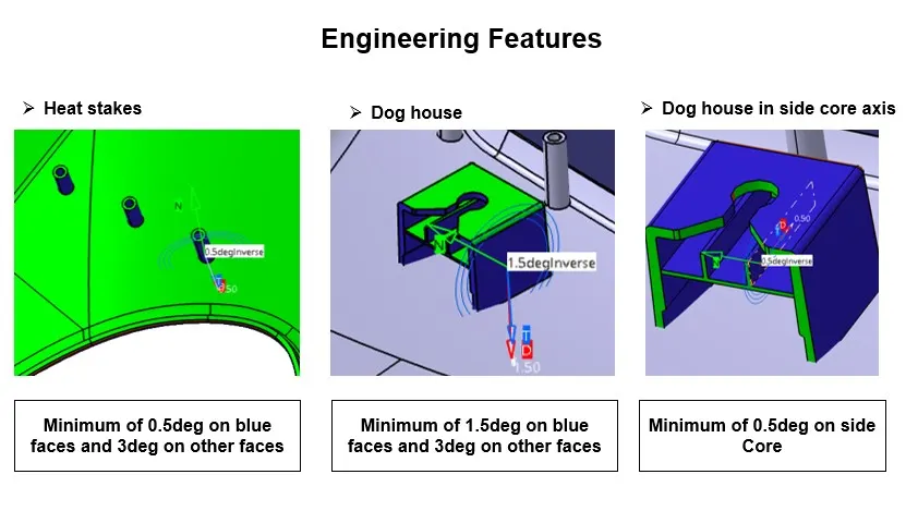
Heat stakes
Heat staking is a process used to join plastic parts by deforming the plastic with heat and force. It’s especially useful for bonding metal to plastic, and it's commonly applied in high-volume, low-cost industries like automotive, IT, and consumer appliances. The process involves heating a plastic part to deform it and fix another part in place. It can join both similar and dissimilar materials, such as metal to metal, plastic to plastic, or metal to plastic. Heat staking allows for precise control within a narrow process window, local heating that avoids damage to surrounding materials, and can be used with glass-filled materials. It doesn’t involve mechanical vibration and offers flexibility in creating various heat-stake shapes with custom-designed tools.
Ribs
Ribs are integral to enhancing the stiffness and strength of plastic parts without adding to their overall thickness. They serve multiple functions, such as acting as locators and arresting features in assemblies, ensuring accurate alignment of components, and functioning as stops or guides for parts like tilted headlamps. Effective rib design involves careful consideration of thickness to balance strength and moldability, quantity to provide adequate support, height to avoid sink marks, manufacturability to ensure ease of production, and strategic location to optimize performance and alignment. Properly designed ribs contribute to the durability and functionality of the component.
Dog House
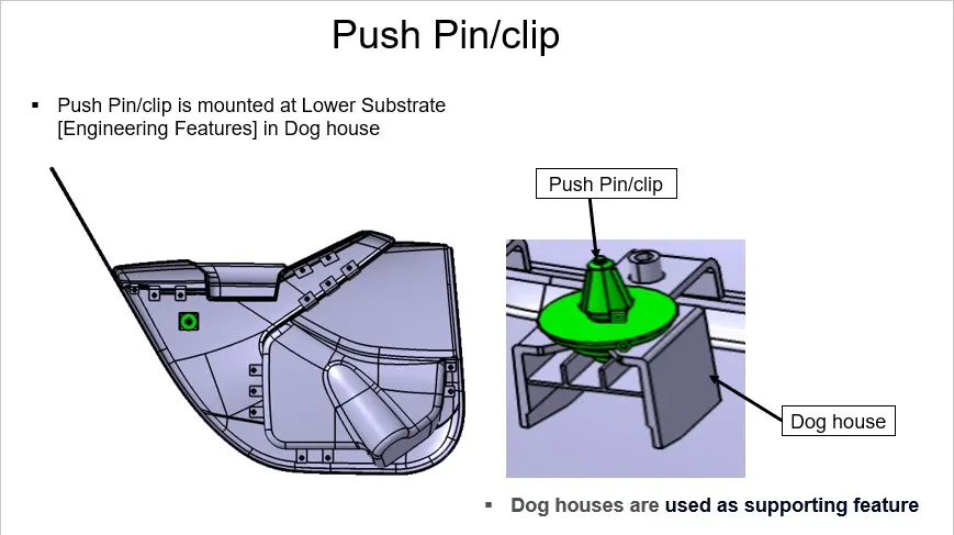
A dog house is an attachment feature used to position components at precise heights and fix plastic defects during assembly. You should use the specific design provided in your resources and follow the master section or engineering drawing closely to ensure accurate placement and effective resolution of issues.
Flange
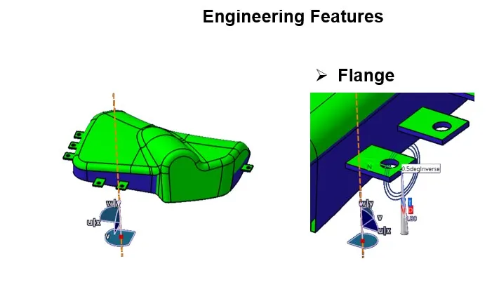
A flange is designed to provide slots for heat stakes and locators, facilitating the assembly of two components and constraining their motion. It acts as a counterpart to ensure proper fitment. In your application, flanges are built into components to align with the lower substrate. The central hole in the flange guides the heat stakes, which are later melted to secure the assembly. Additionally, the flange should rest on supporting ribs on the sides to maintain stability and alignment.