Week 12- Final project
REPORT:
Aim:
- To develop a Door Trim Panel from the given master section by considering the inputs as like in OEM and Tier-1 companies.
- To find a attachment strategy for the door panel complete work.
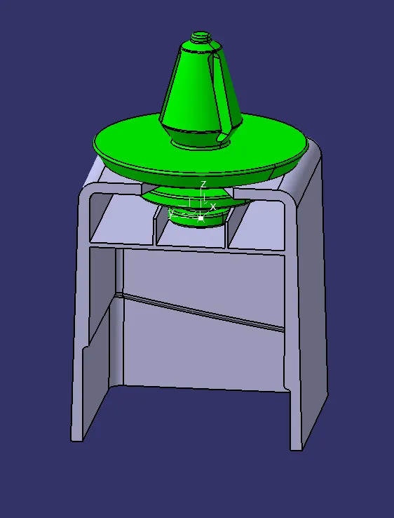
- To use Push pin with Dog house for Lower substrate – Door panel attachment.
- To use heat stakes for part to part attachment.
Objectives:
- To create Iso-constrained sketches,individual tooling axis and perform draft analysis.
- To create thickened part using master section for reference.
- To create the mounting features as per design guidelines in the industry and with master sections.
Software Used: CATIA V5
Commands Used:
- Point,line,plane,Positioned sketch,constraint,extract,thick surface,extrude,offset,split,trim,edge fillet,extrapolate,axis,measure item,measure between,join,intersection,circle,boundary,sweep,spline,multiple extract,multi-section surface,curve smooth,geometrical set,body,publications,close surface,pad,translate,draft,draft analysis,existing component,contact constraint,offset constraint,manipulation,graph tree reordering,normal view,isometric view,create multi-view,fit all in,customize view parameters,part.
Procedure:
- Given class-A surface & master sections.
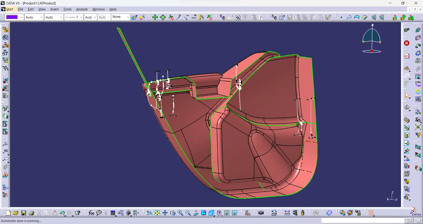
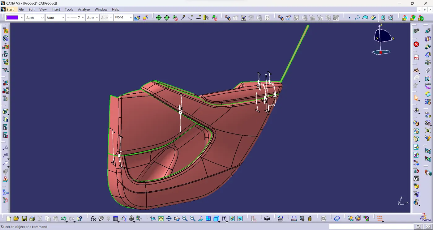
Tooling Axis:
- Tooling axis is created for all the parts individually.
Draft Analysis on class-A surface:
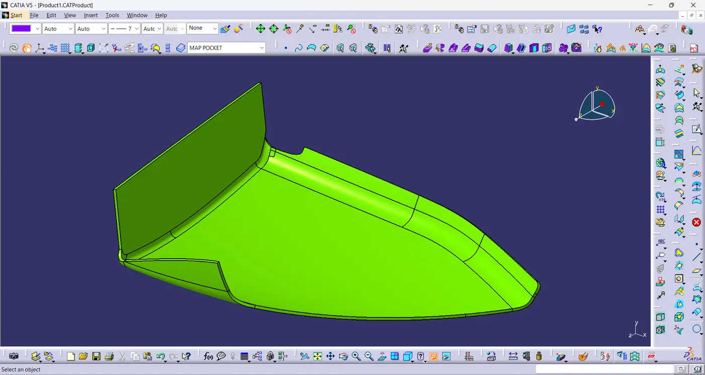
Map Pocket:
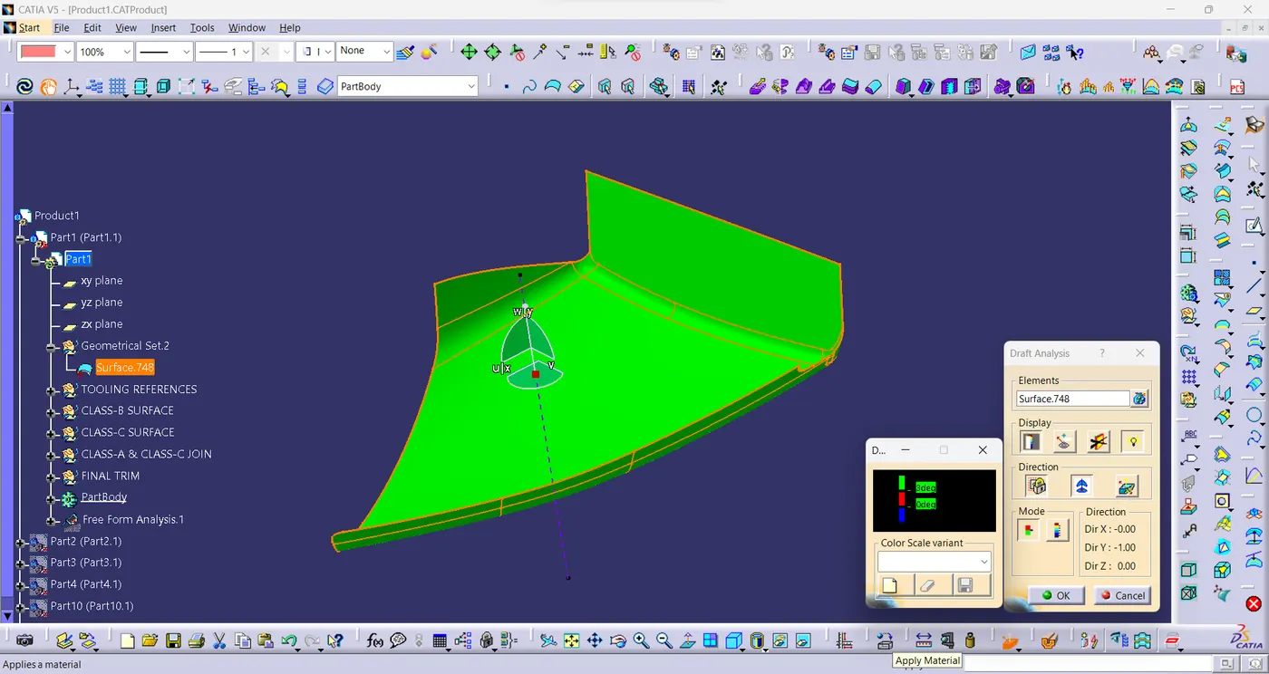
- Draft analysis is performed on the class-A surface of map pocket with 3 degree draft angle
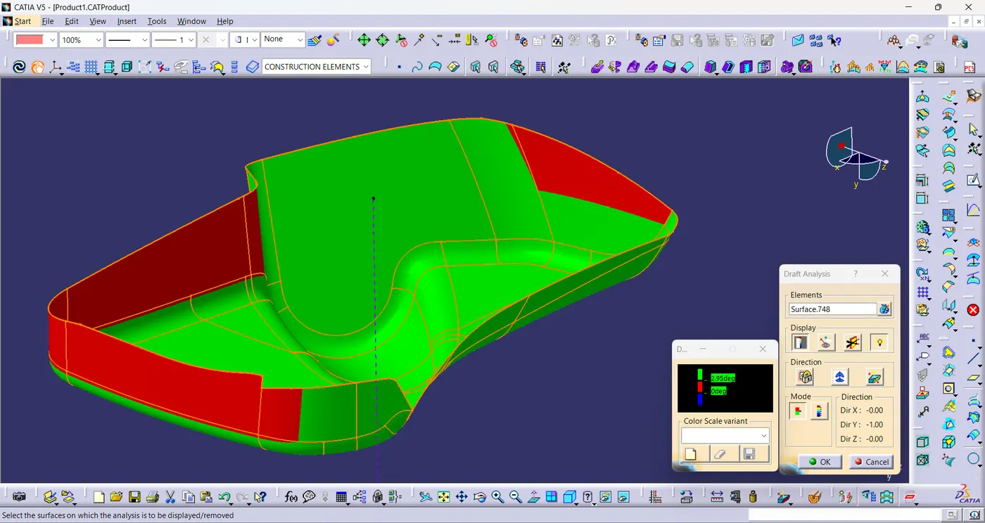
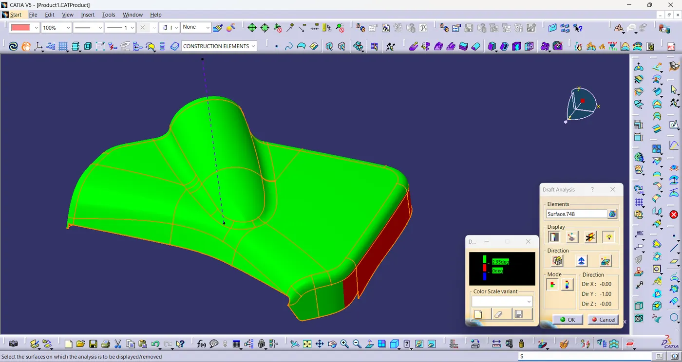
Bottle Holder:
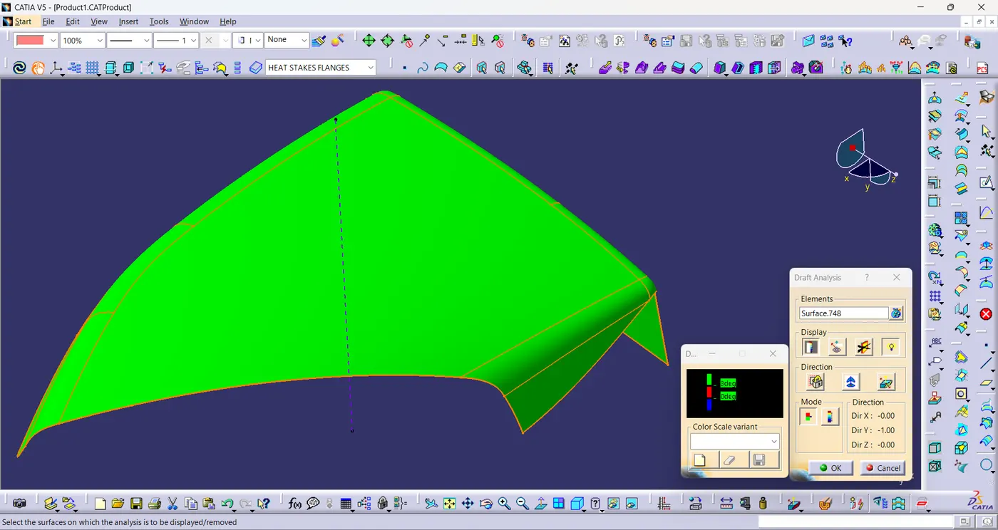
- Draft analysis is performed on the class-A surface of bottle holder with 3 degree draft angle.
Lower Substrate:
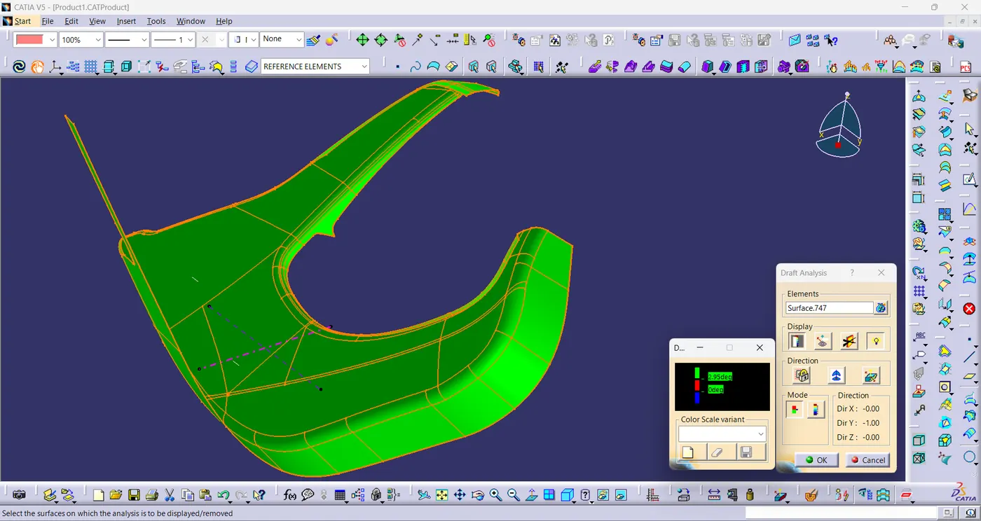
- Draft analysis is performed on the class-A surface of lower substrate with 3 degree draft angle.
Arm Rest:
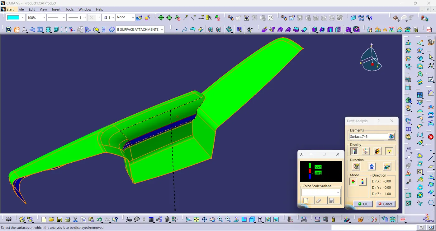
- Draft analysis is performed on the class-A surface of arm rest with 3 degree draft angle
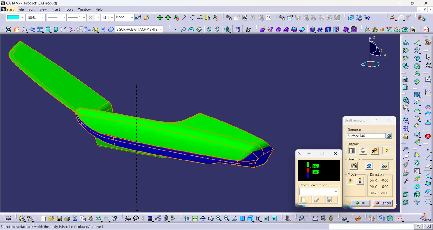
Map Pocket:
- The class-A surface of map pocket is given and the tooling axis is created for the map pocket.
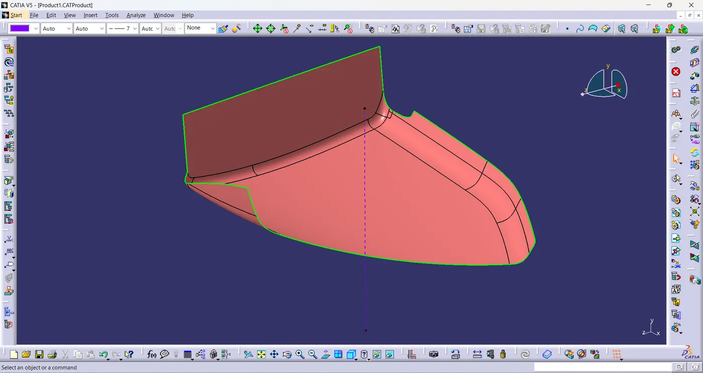
Class-B surface:
- The given class-a surface is directly offsetted by 2.5mm and extrapolated the offset surface to create class-B surface.
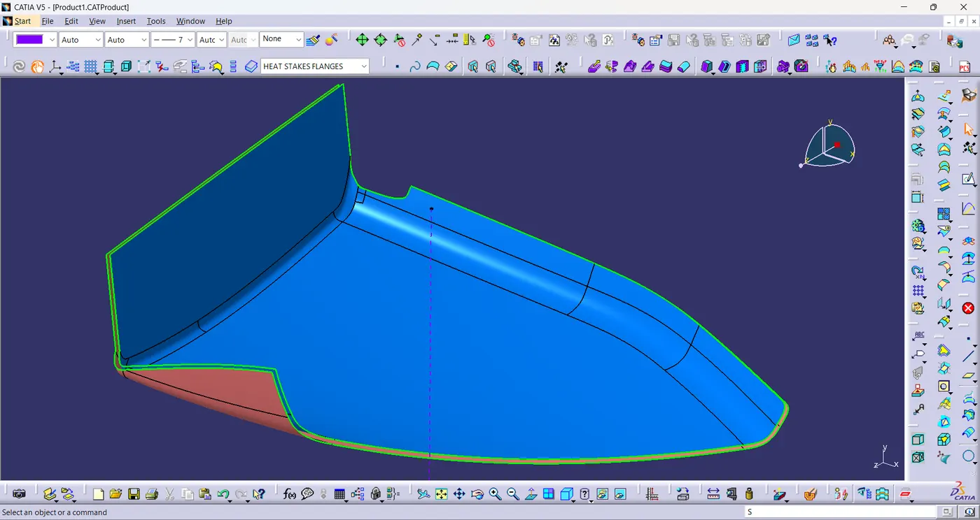
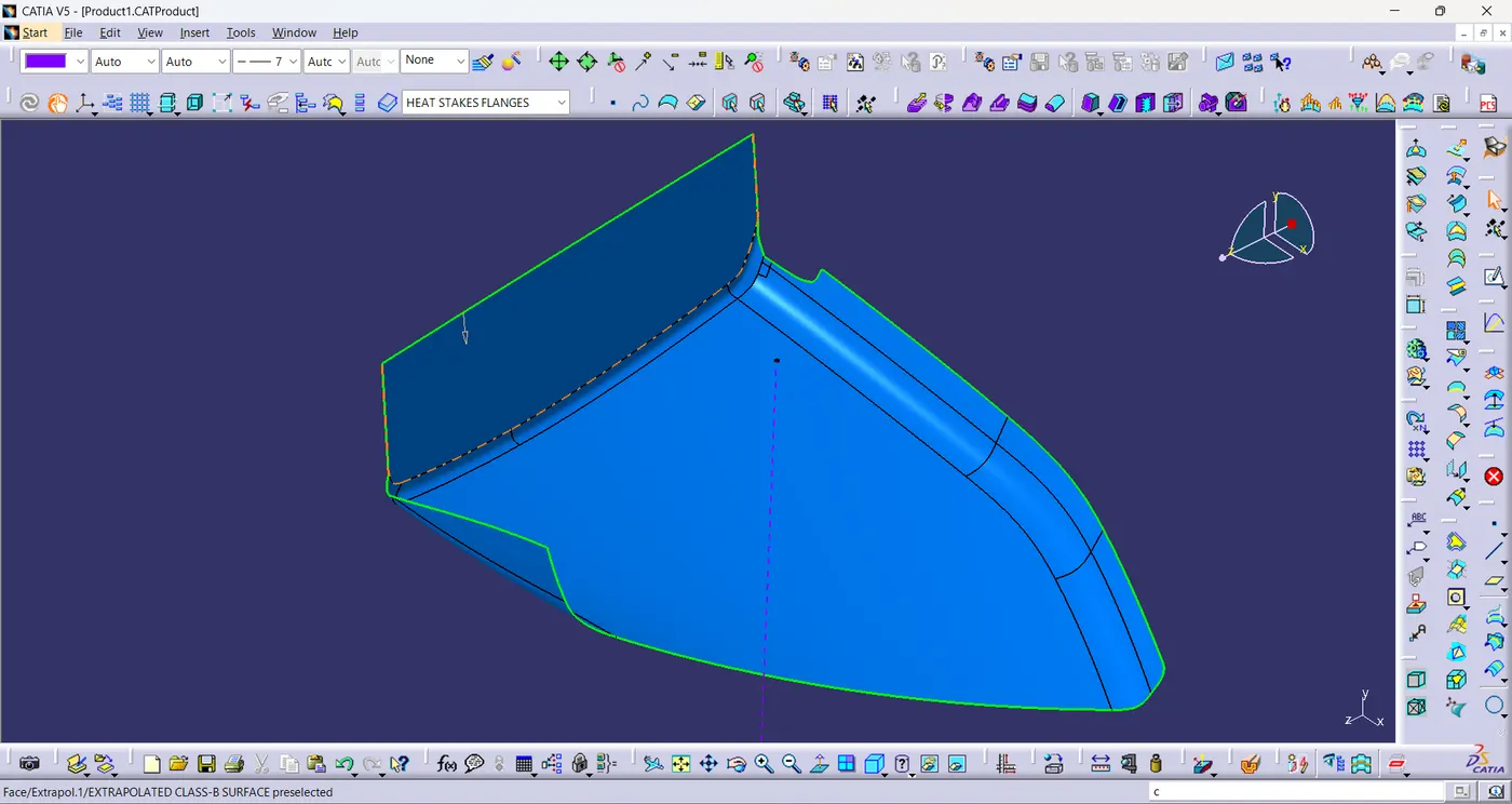
Class-C Surface:
- A boundary is created using class-A surface.
- And then using the boundary a sweep is created with profile type as line and subtype as with reference surface with the draft direction in 87°.
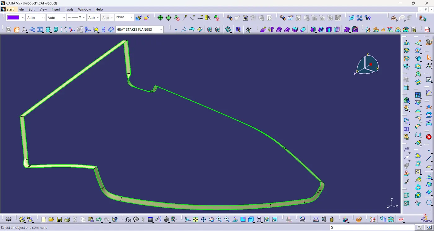
Final Plastic Component:
- Unhide the Class-A&C join surface and the class-B surface.
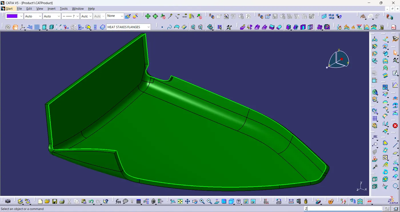
- Now create intersection between class-A&C join and the class-B surface.
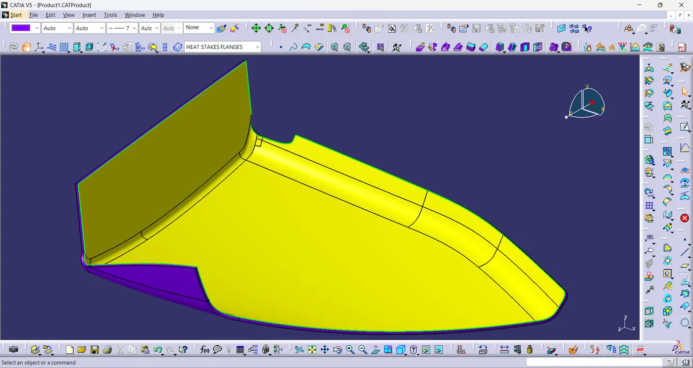
- split both the surfaces with intersection and using join command join the splits to form final plastic component.
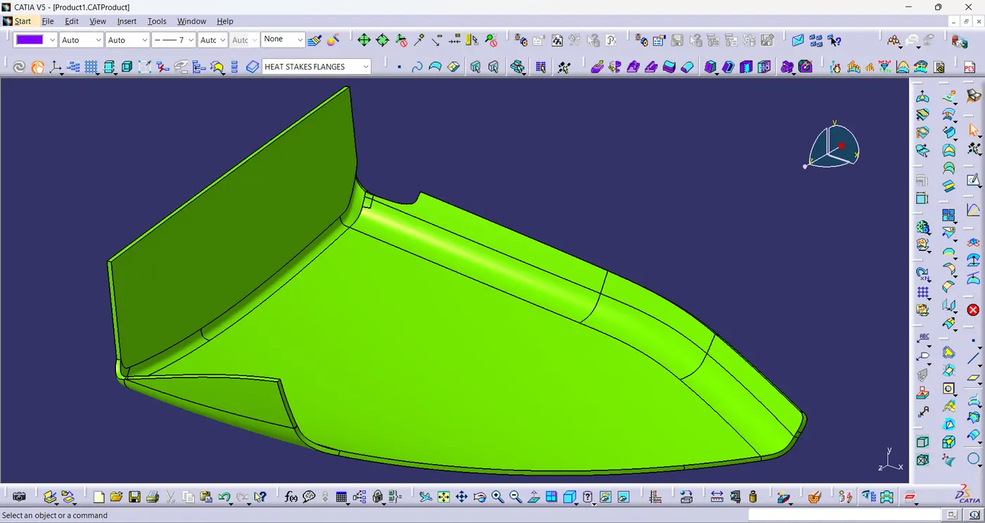
Solid Component:
- Using close surface,a solid model of the map pocket is created from the plastic component.
Bottle Holder:
- The class-A surface of bottle holder is given and the tooling axis is created for the bottle holder.
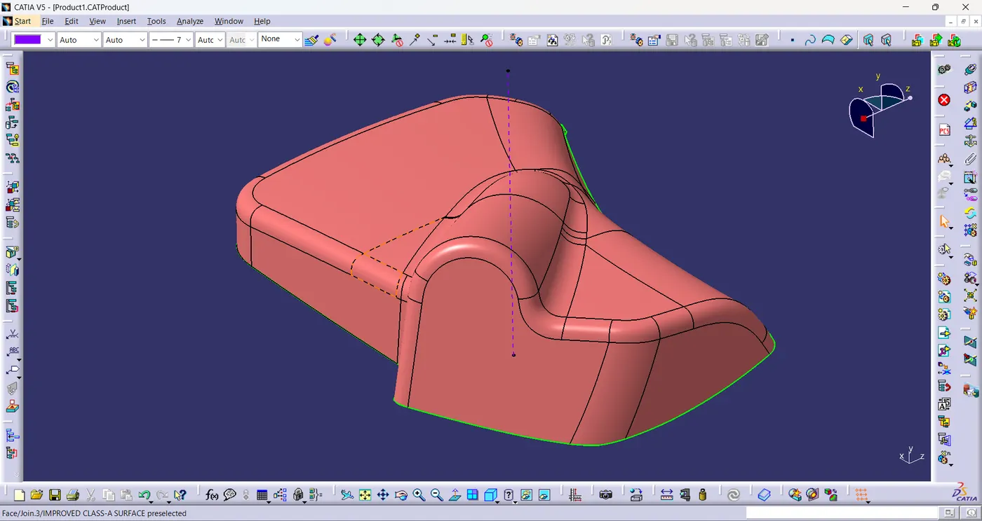
- The class-A surface has a missing patch as shown in the figure.
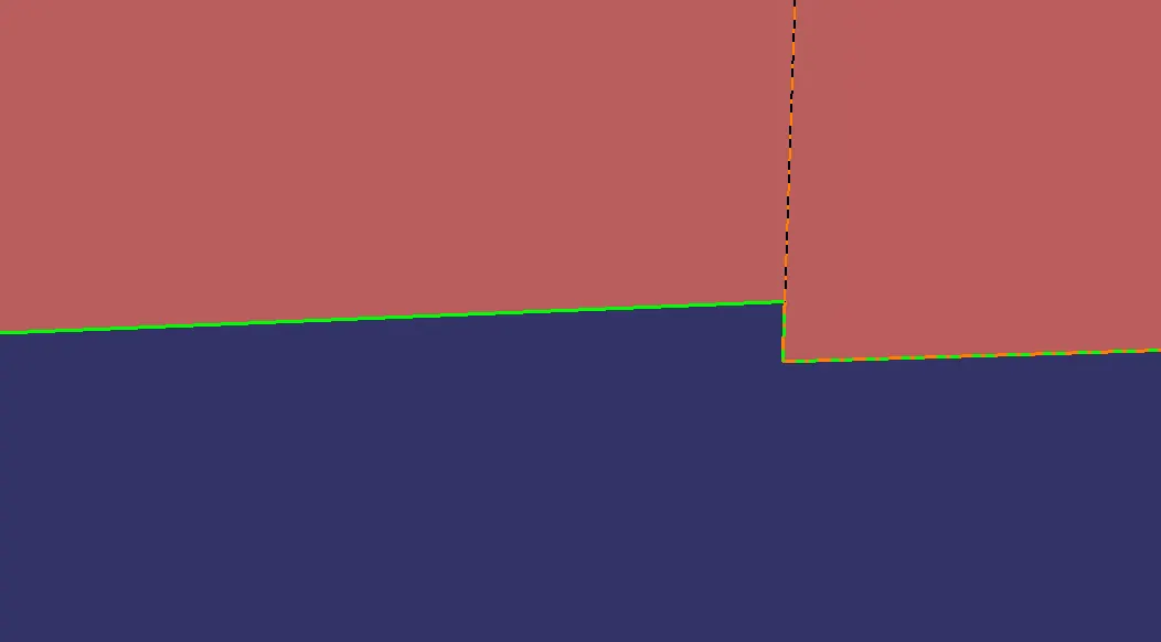
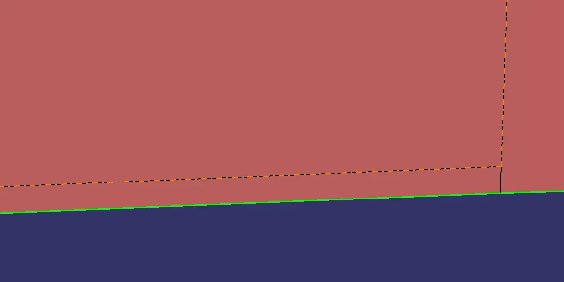
- Then the missing patch is improved by using boundary,multi section surface and join command.
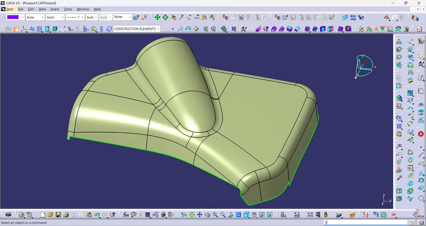
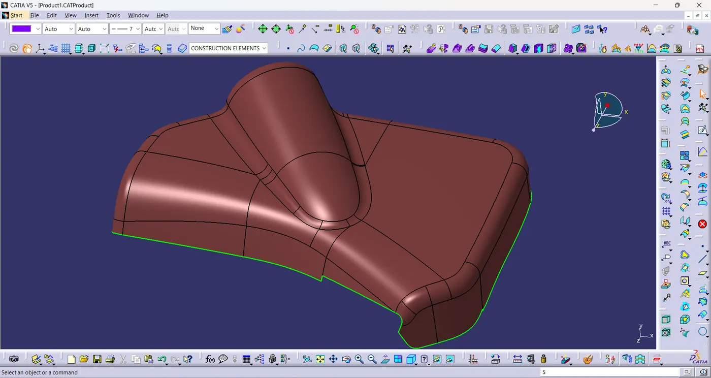
Class-B surface:
- The given class-a surface is directly offsetted by 2.5mm and extrapolated the offset surface to create class-B surface.
Class-C surface:
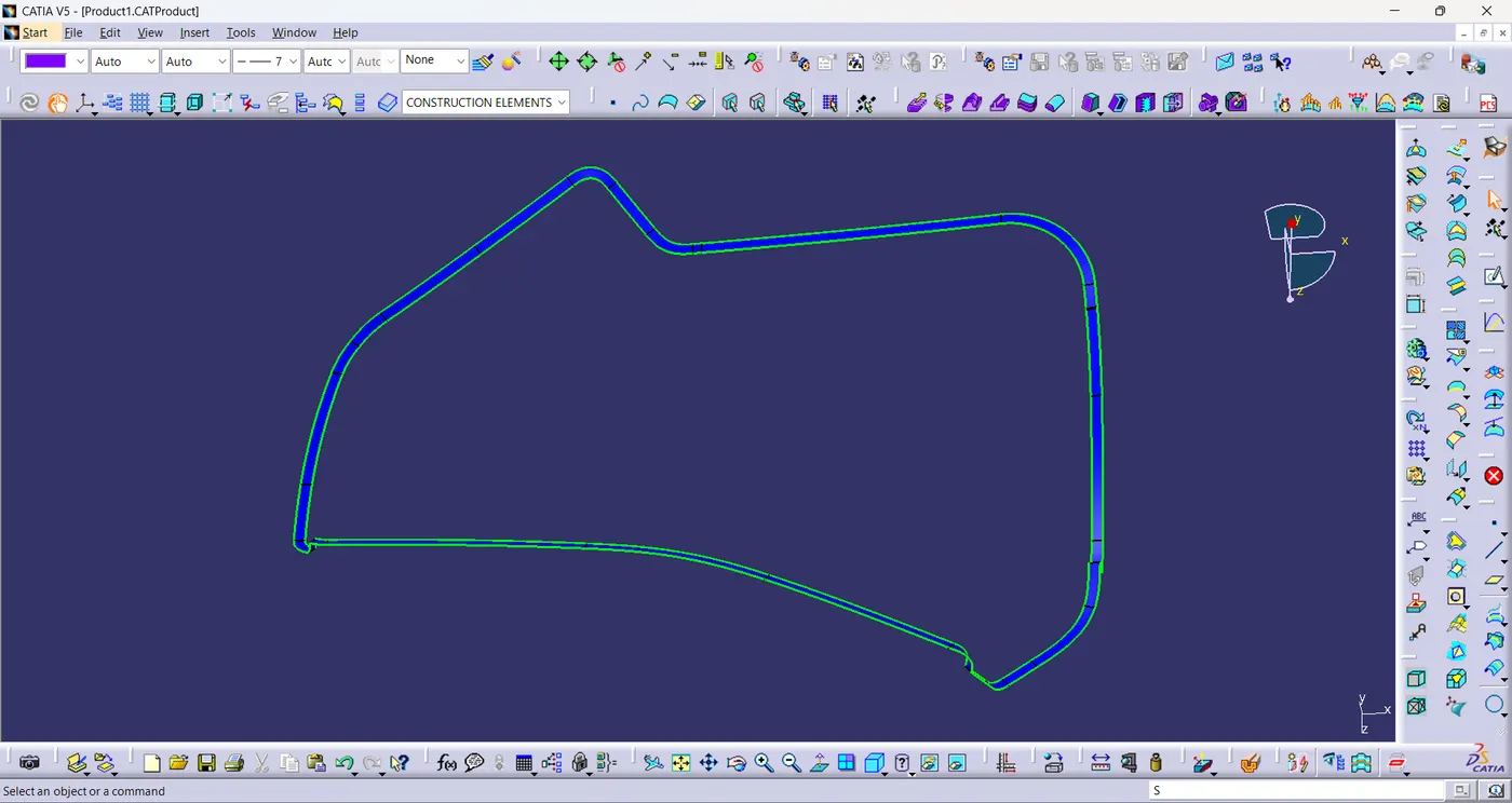
- A boundary is created using class-A surface.
- And then using the boundary a sweep is created with profile type as line and subtype as with reference surface with the draft direction in 87°.
Final Plastic Component:
- Unhide the Class-A&C join surface and the class-B surface.
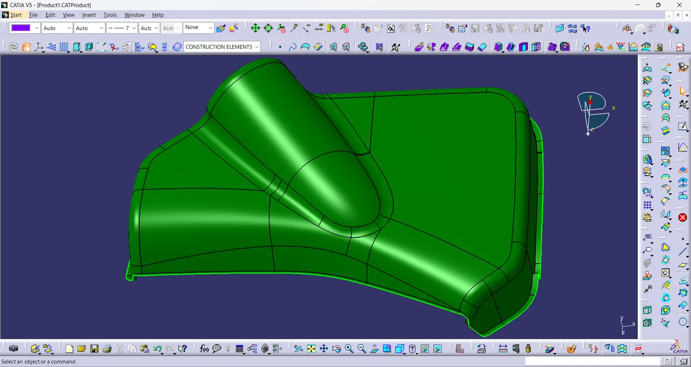
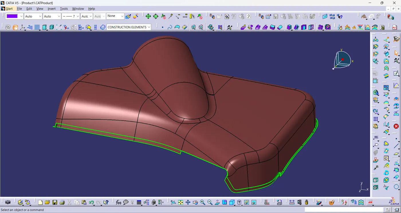
- Now trim the unwanted surfaces to create plastic component.
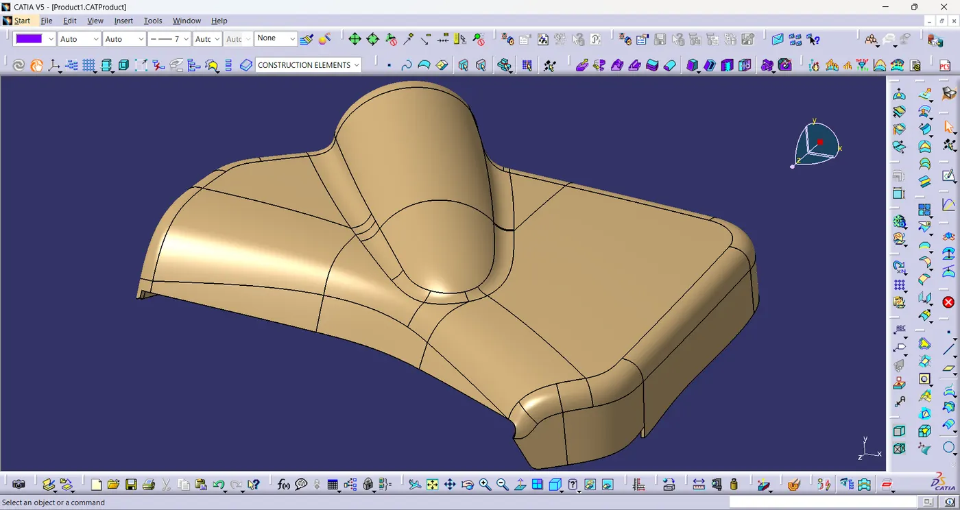
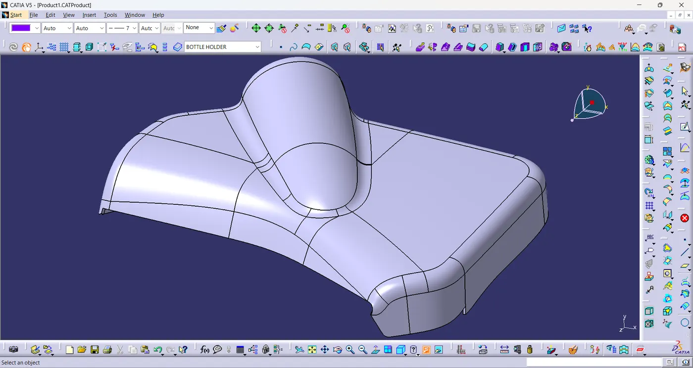
Solid Component:
- Using close surface,a solid model of the bottle holder is created from the plastic component.
Lower Substrate:
- The class-A surface of bottle holder is given and the tooling axis is created for thelower substrate.
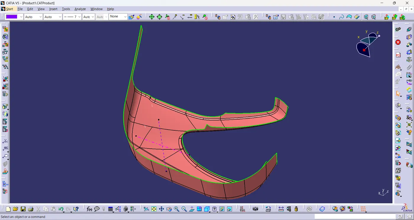
Class-B surface:
- The given class-a surface is directly offsetted by 2.5mm and extrapolated the offset surface to create class-B surface.
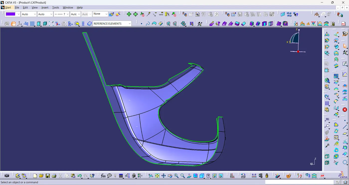
Class-C surface:
- A boundary is created using class-A surface.
- And then using the boundary a sweep is created with profile type as line and subtype as with reference surface with the draft direction in 87°.
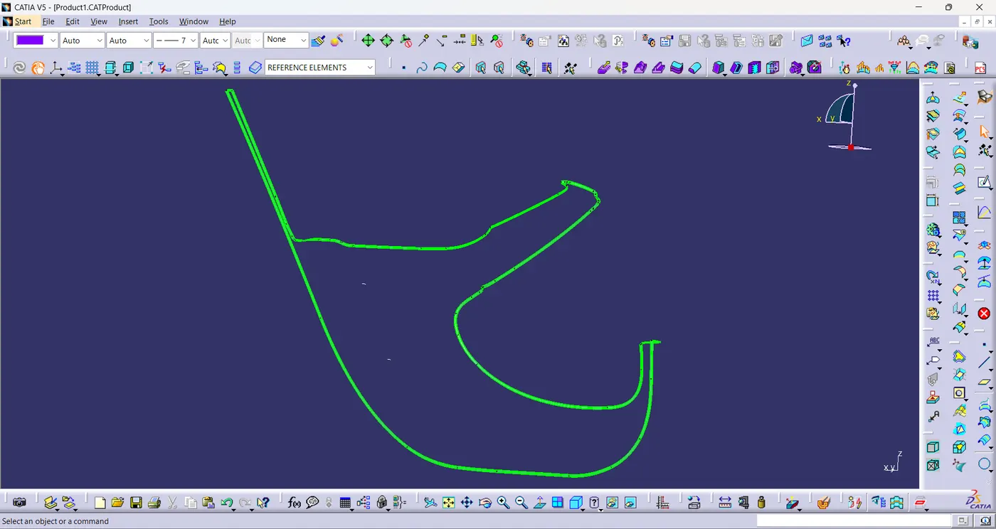
Final Plastic Component:
- Unhide the Class-A&C join surface and the class-B surface.
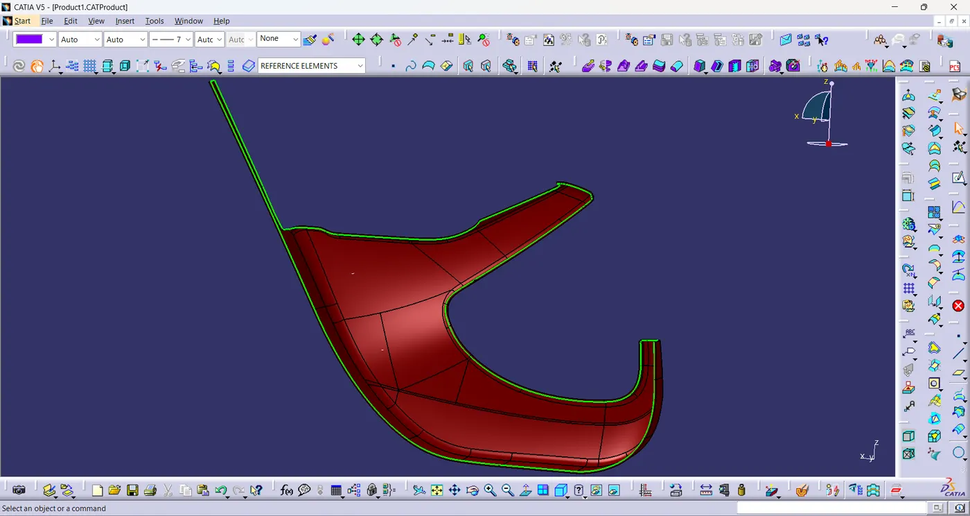
- Now trim the unwanted surfaces to create plastic component.
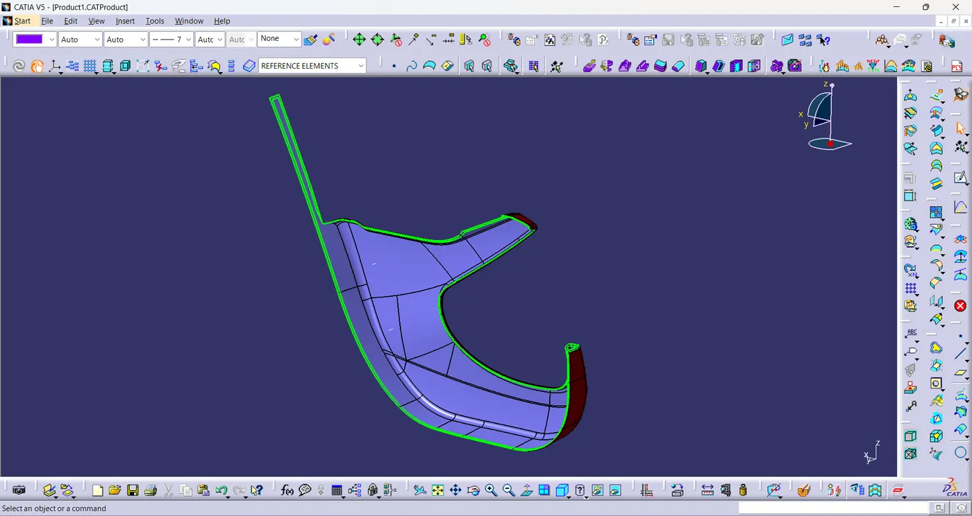
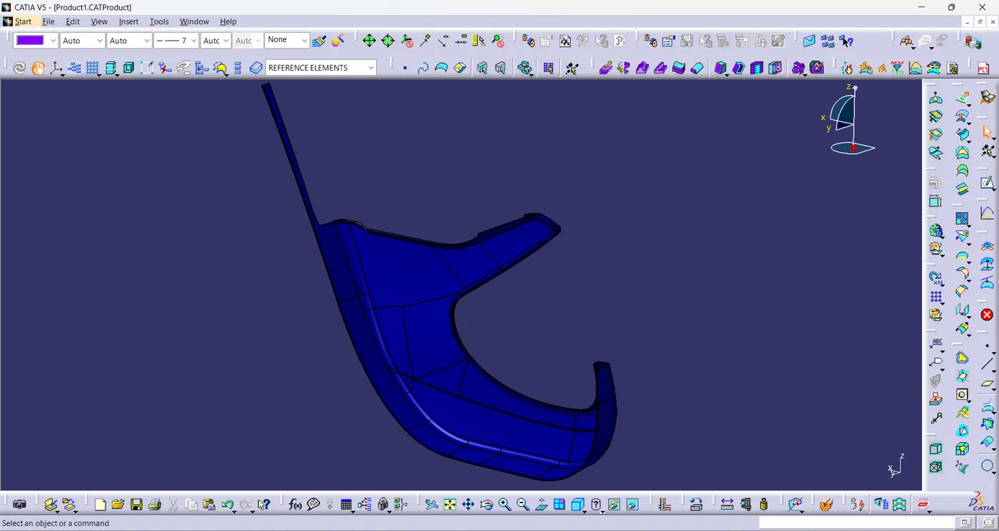
Solid Component:
- Using close surface,a solid model of the lower substrate is created from the plastic component.
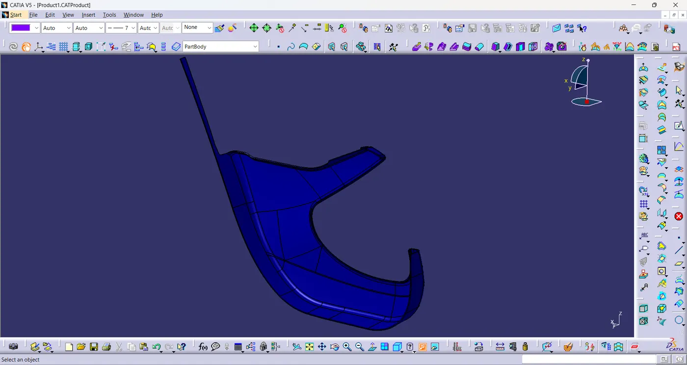
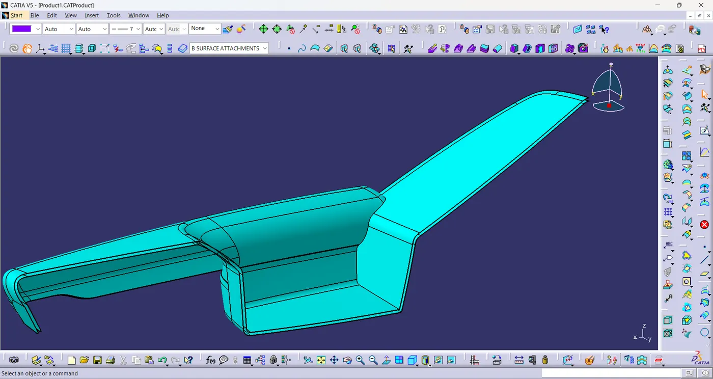
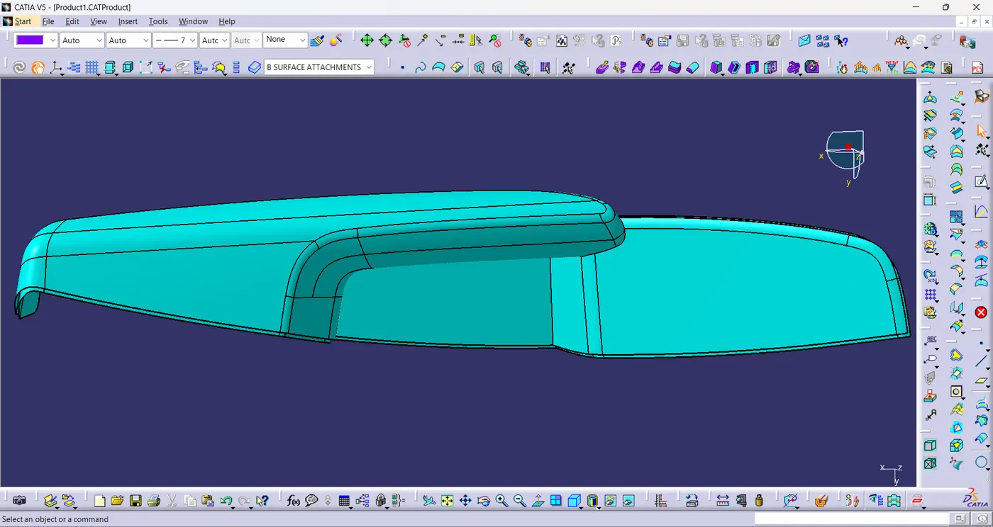
Arm Rest:
- The class-A surface of bottle holder is given and the tooling axis is created for the arm rest.
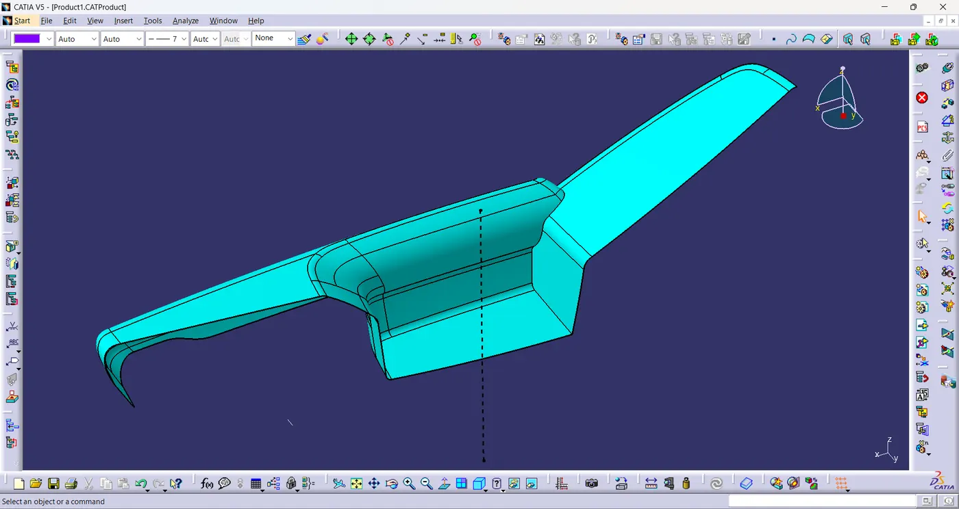
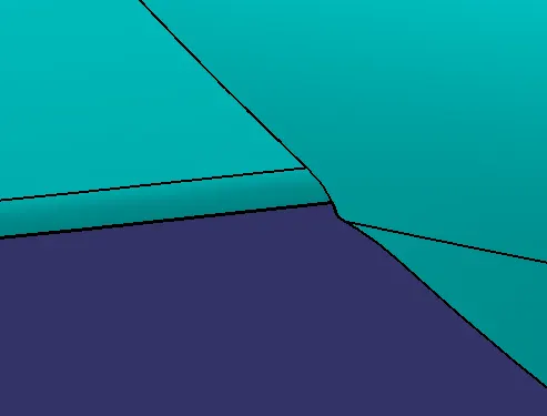
- The class-A surface has a missing patch as shown in the figure.
- Then the missing patch is improved by using multiple extract,extrapolate,trim,spline,split command.

Class-B surface:
- The given class-a surface is directly offsetted by 2.5mm and extrapolated the offset surface to create class-B surface.
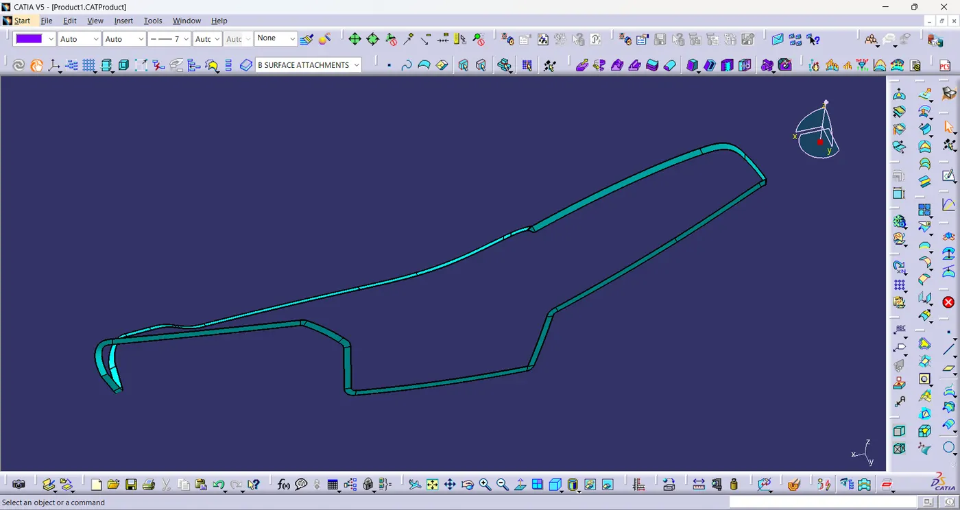
Class-C surface:
- A boundary is created using class-A surface.
- And then using the boundary a sweep is created with profile type as line and subtype as with reference surface with the draft direction in 90°.
Final Plastic Component:
- Unhide the Class-A&C join surface and the class-B surface.
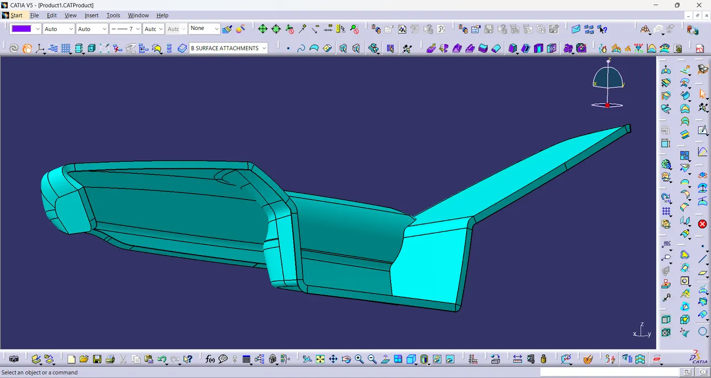
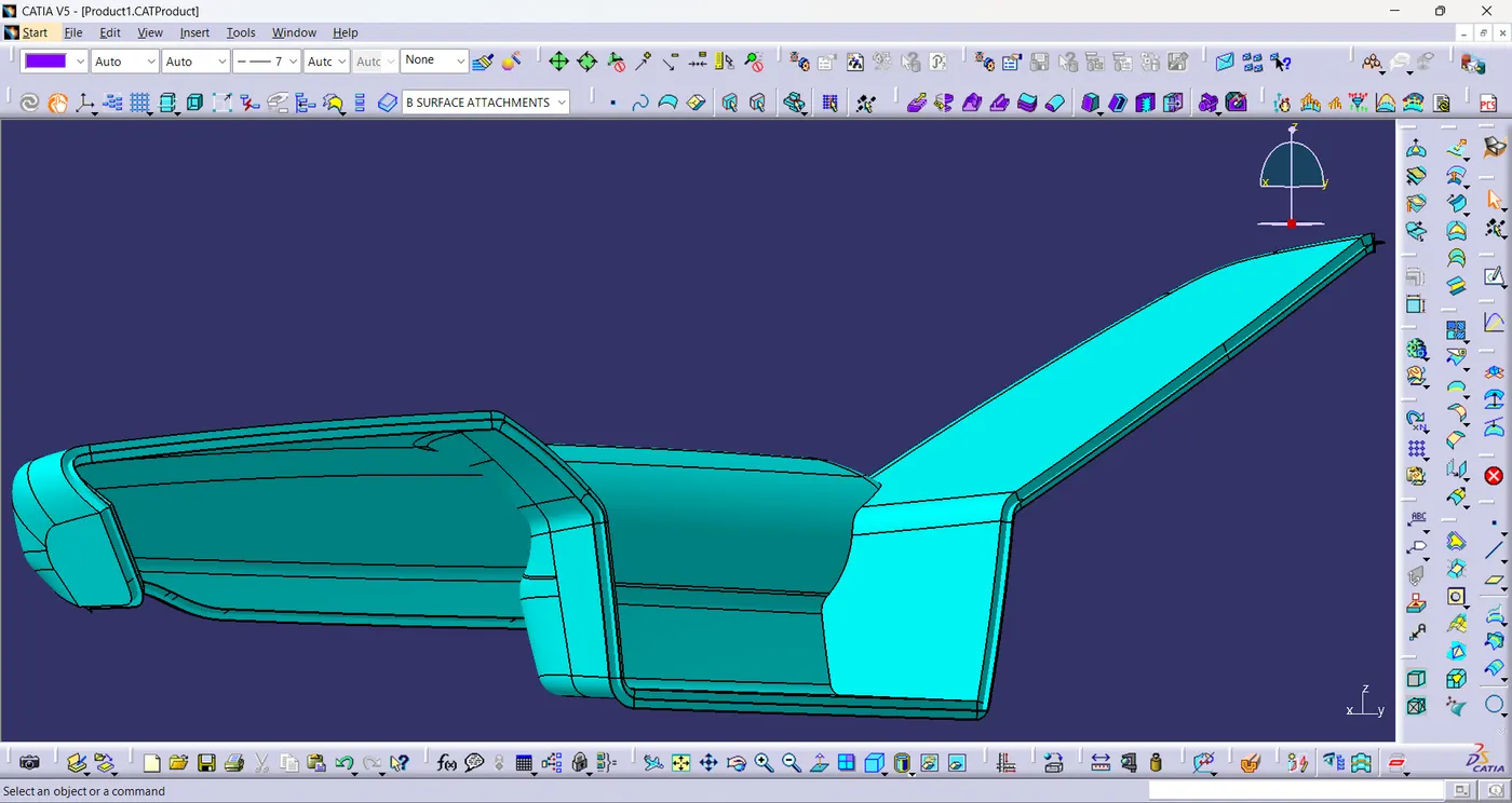
- Now trim the unwanted surfaces to create plastic component.
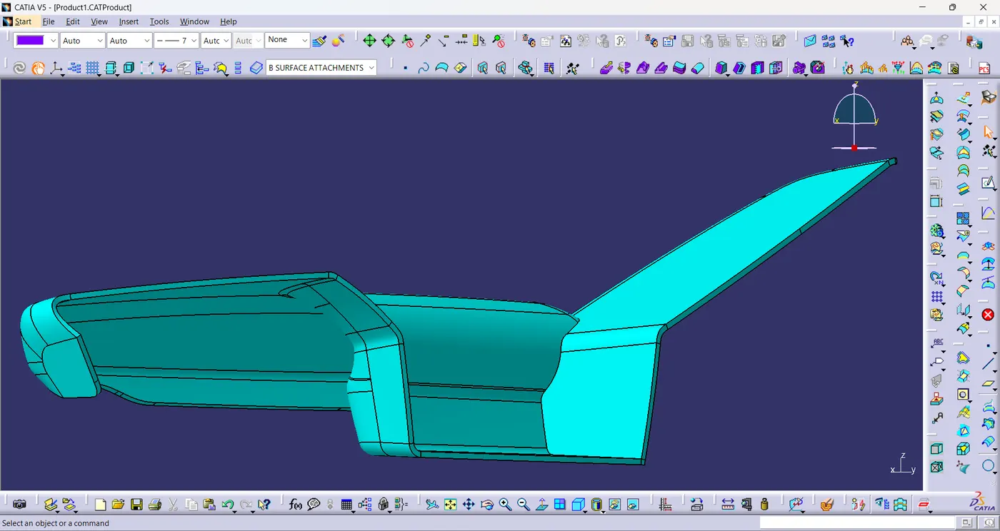
Solid Component:
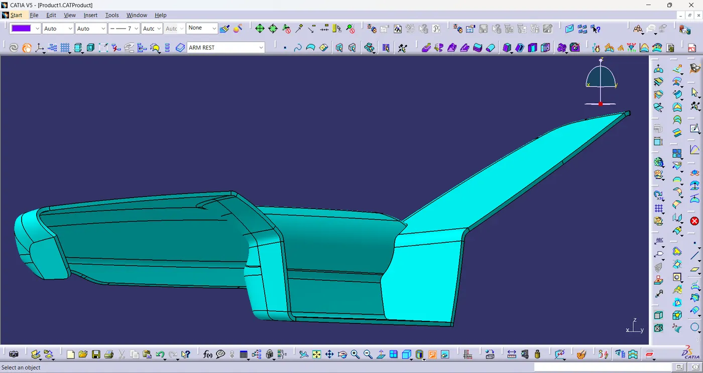
- Using close surface,a solid model of the arm rest is created from the plastic component.
Engineering Features:
Flanges:
- The sketchs for flange is extracted from the given master section of door panel.
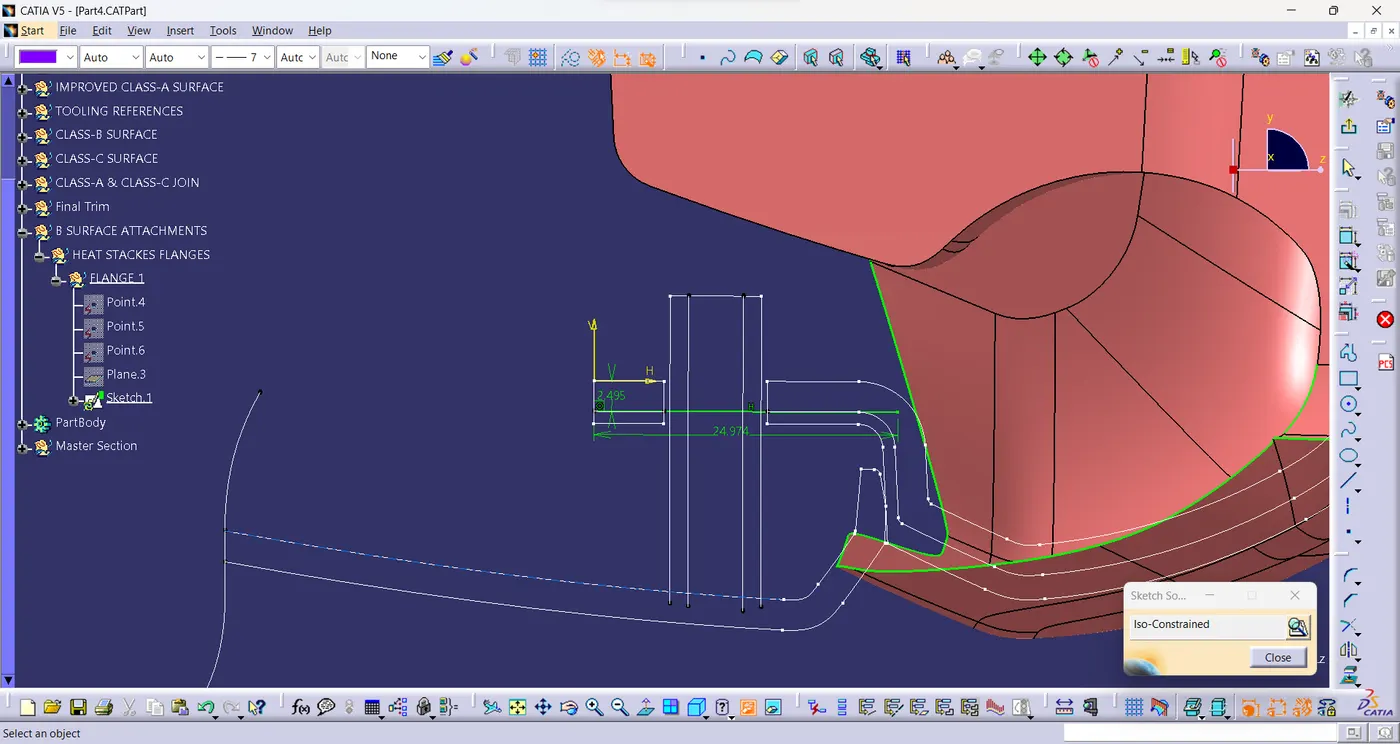
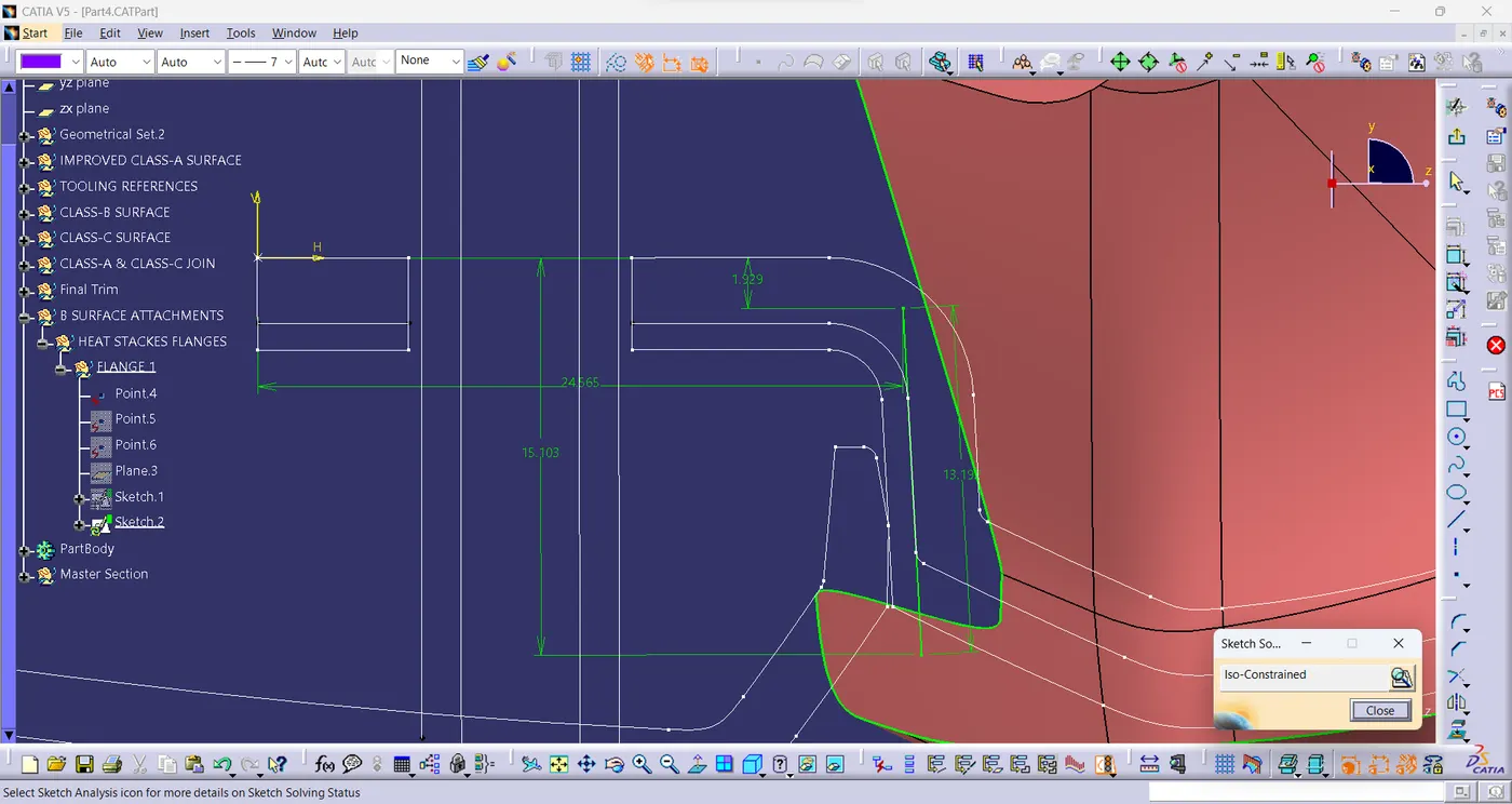
- The sketches are extracted,sweeped and extrapolated to create surfaces.
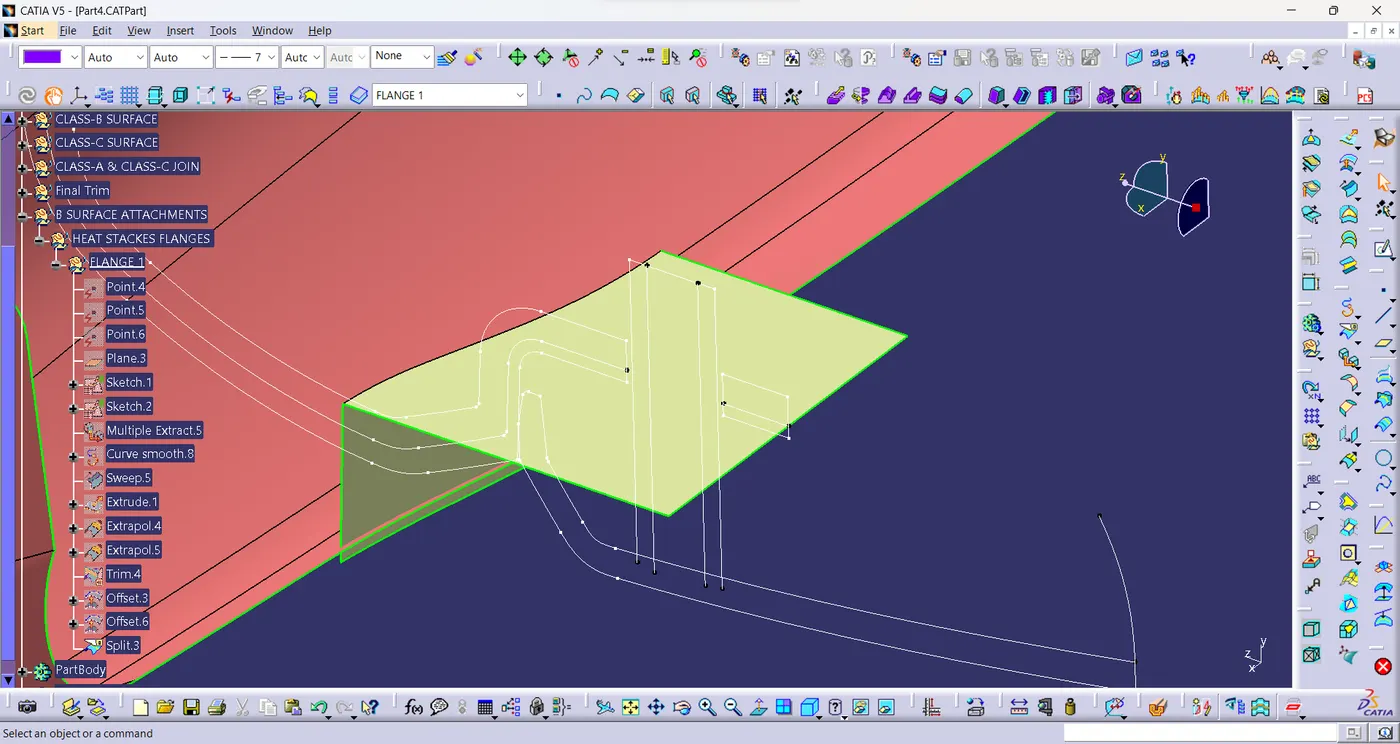
- The surface is now thickened and the edges are filleted.
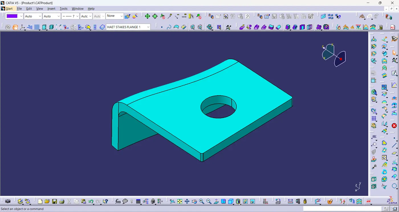
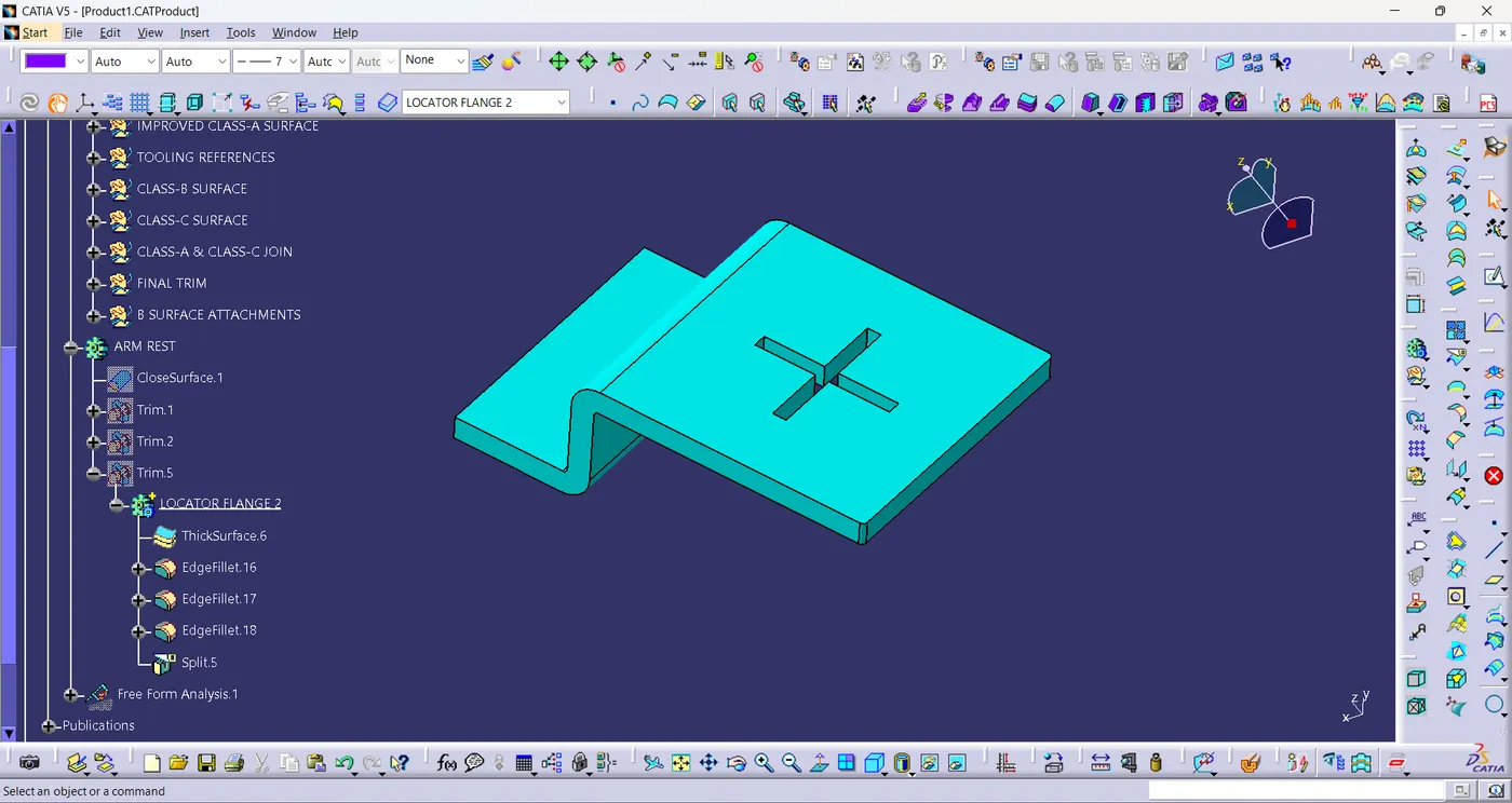
- Based on the attachement, the flange is created for heat stake and locator.
Heat Stake:
- The sketch of the heat stake is created and paded according to the 25mm in y-axis.
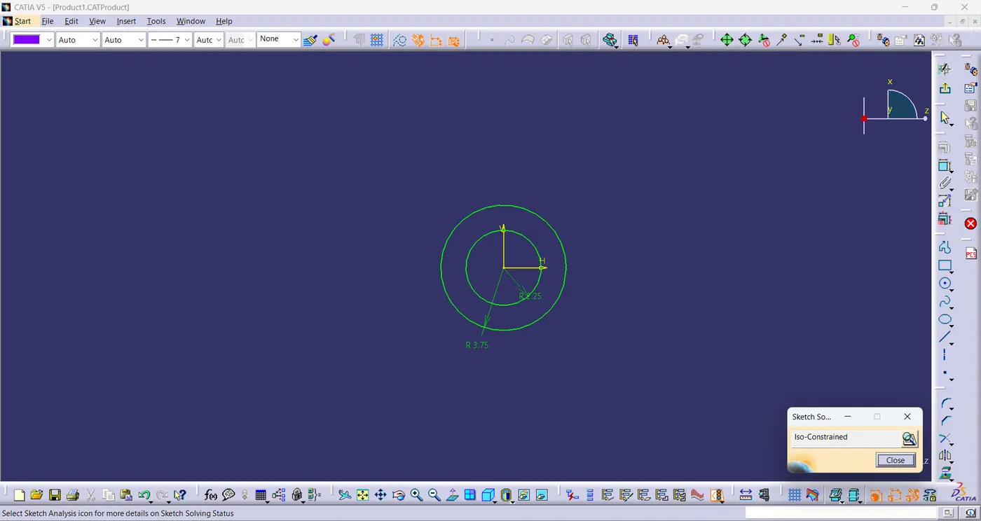
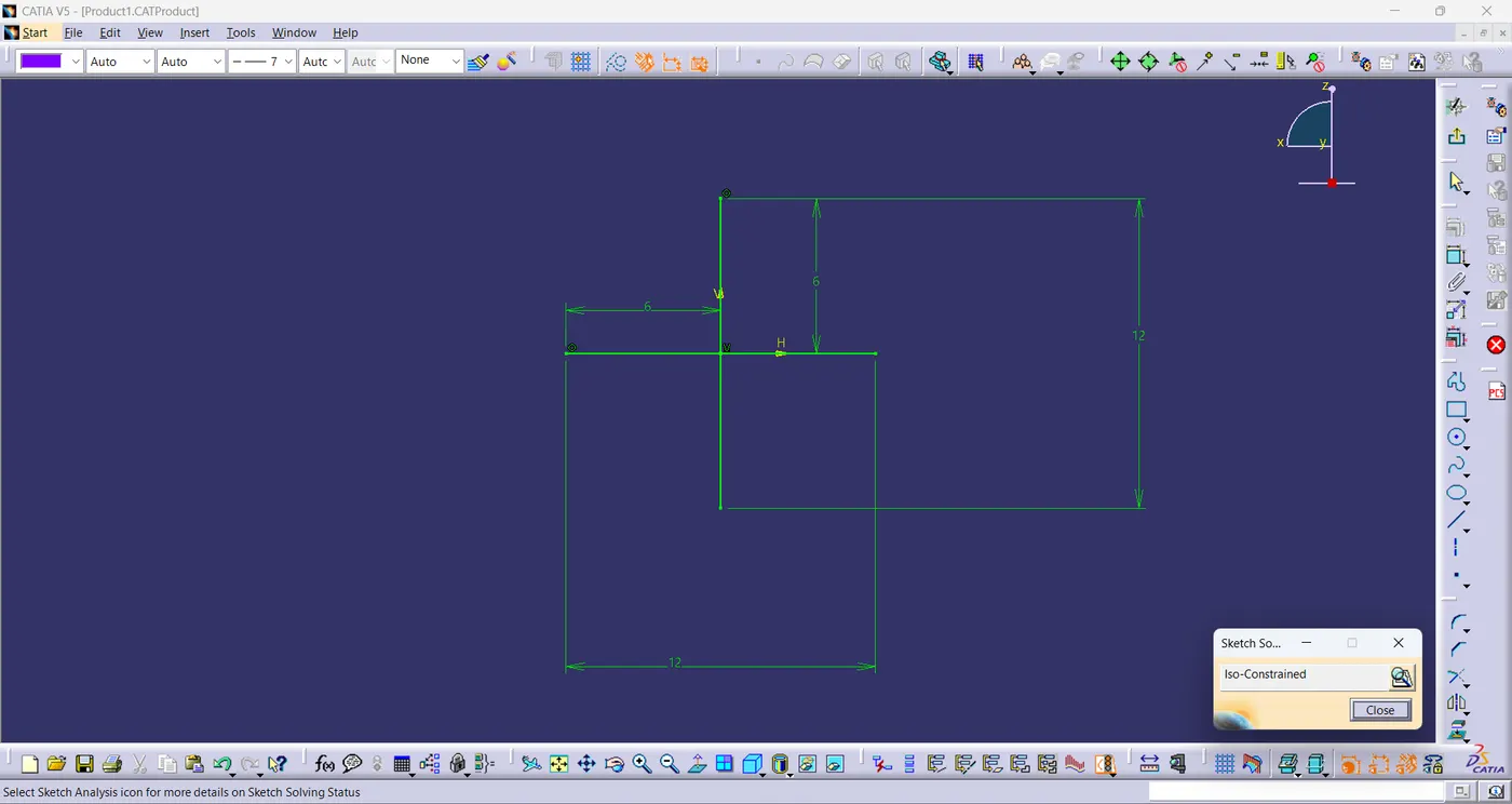
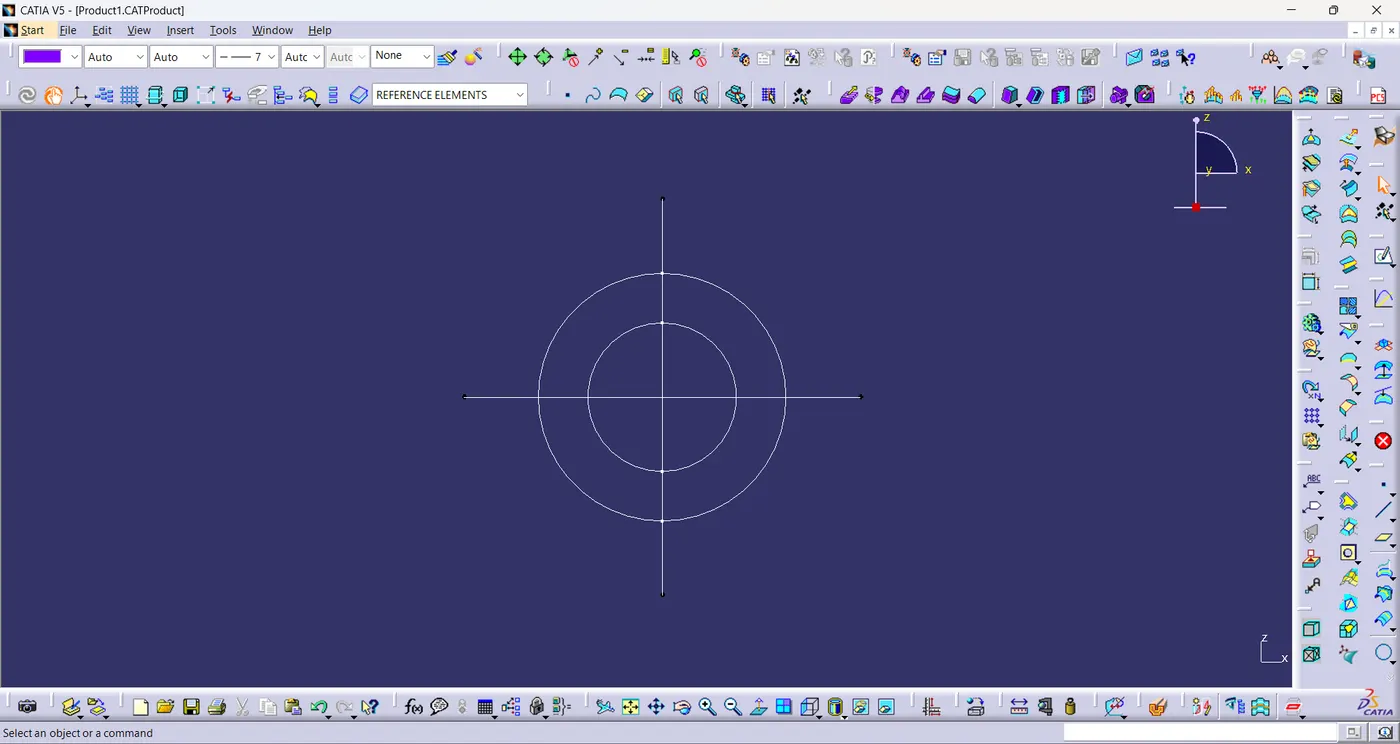
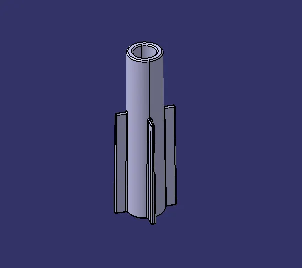
- The heat stake is provided a draft of 0.5° and filleted with a value of 0.25mm
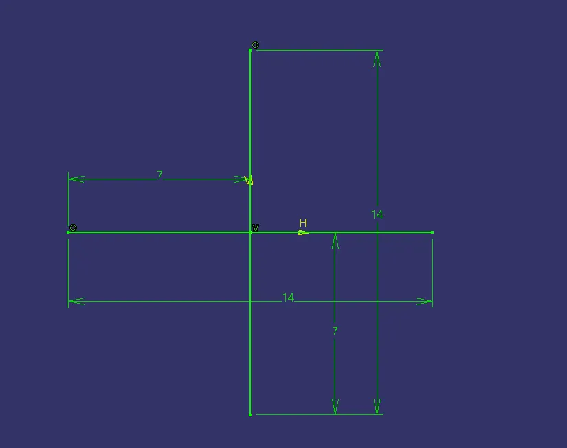
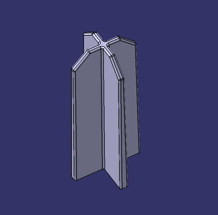
4-Way Locator:
- The sketch of the 4-Way locator of measurement 14mmx14mm is created.
- The sketch is paded using pad command.
- And Provided a draft of value 0.5°,chamfered the edges a length of 3mm and given a fillet value of 0.3mm.
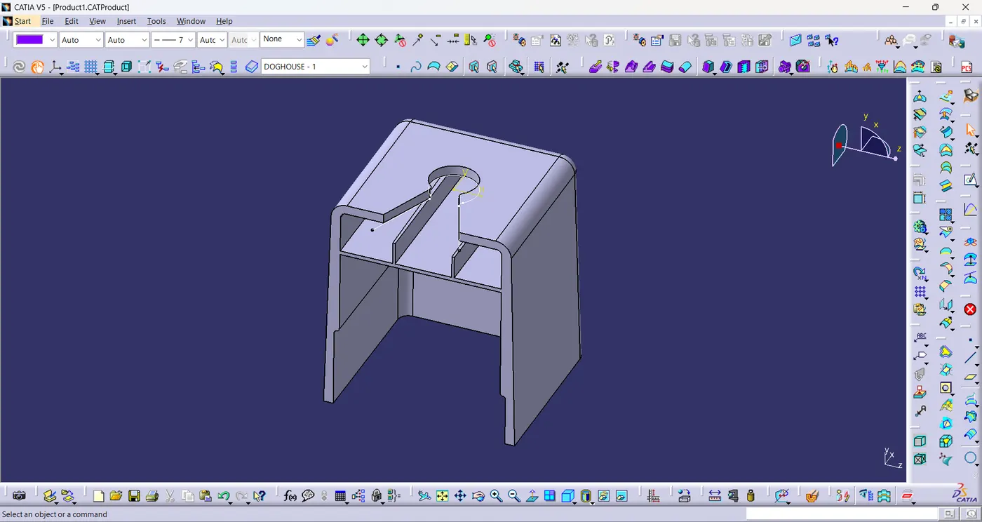
Doghouse:
- The sketch of the doghouse of measurement 30mmx30mm is created.
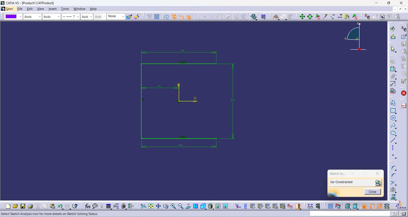
- Extrude the given sketch using extrude command.
- Then extracted the line,extrude the extracted line and offset the line to the required distance.
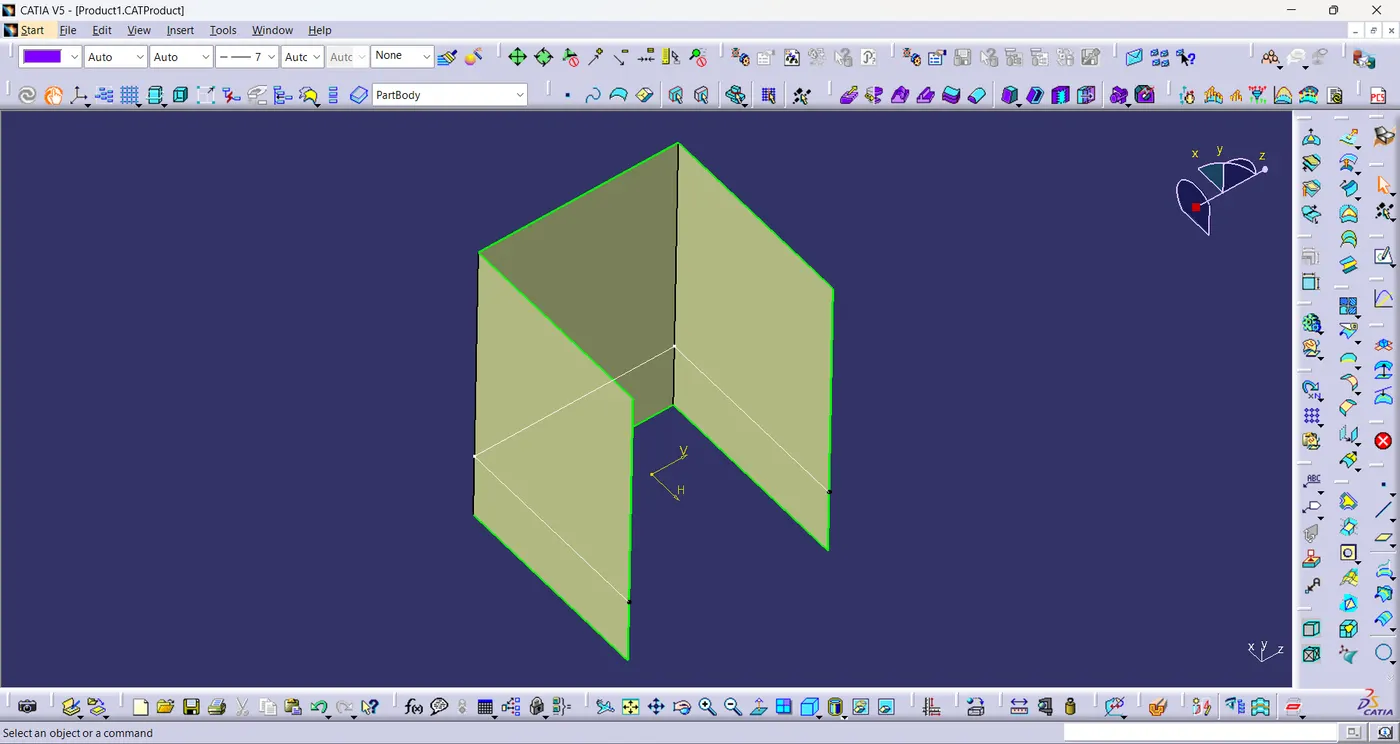
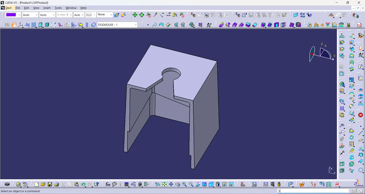
- Now trim the unwanted surfaces to form the doghouse surface.
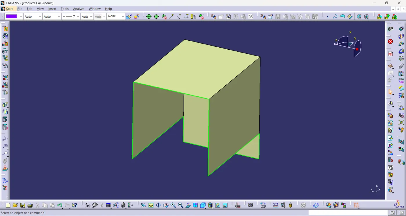
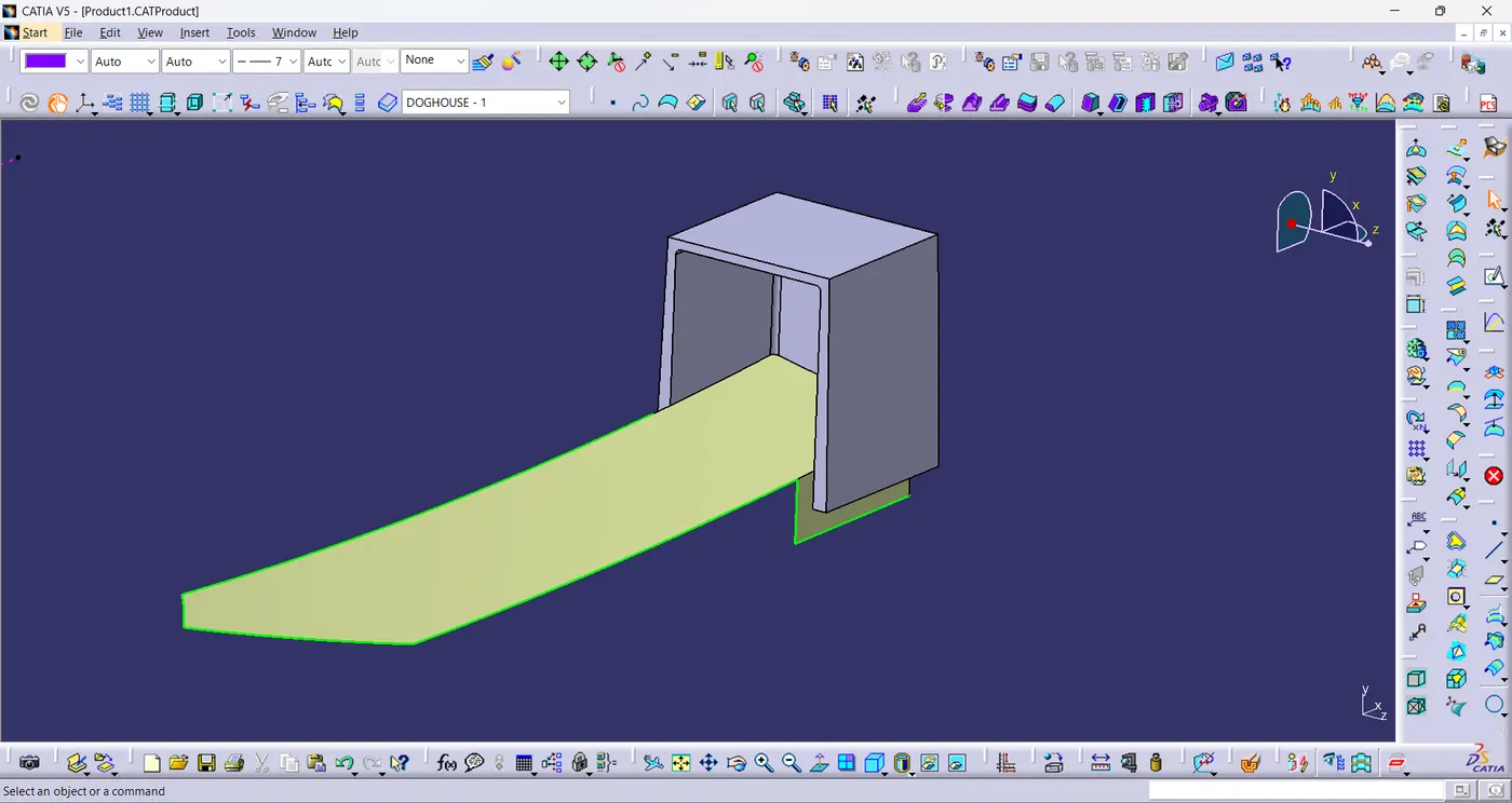
- Now thicken the surface thicken command.
- Create the core part and split it.
- Draft the surfaces of the doghouse(Inner:0.5° & Outer:1.5°).
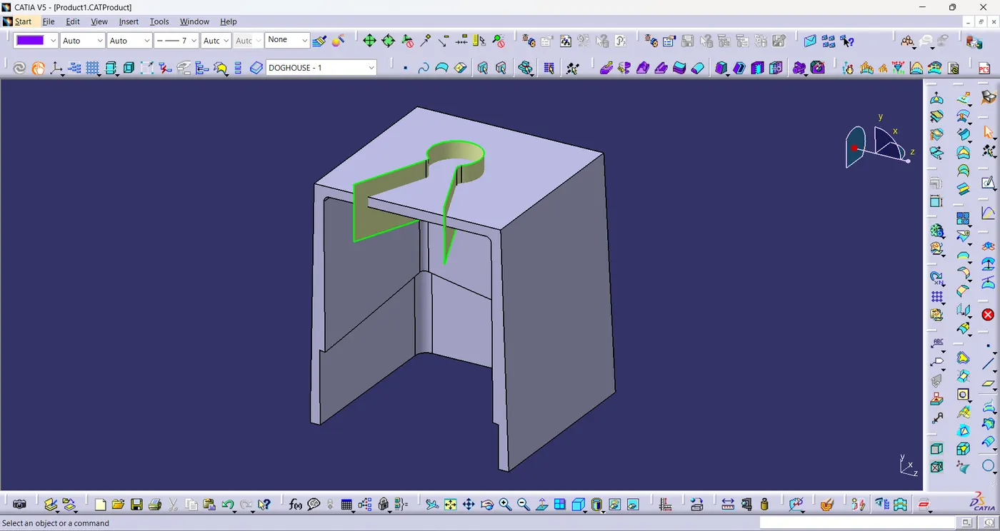
- This is the sketch of the surface cut on the top of the doghouse.
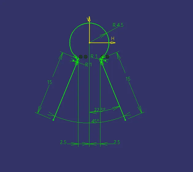
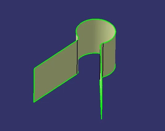
- Extrude the sketch of the surface cut to split it from the top surface of the doghouse.
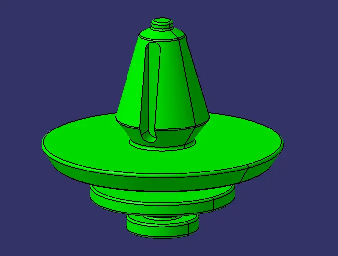
- The sketch of the ribs is created based on the push pin.
- Then extruded the sketch and thickened the extruded surface.
- Now draft the ribs surfaces of angle 0.5°.
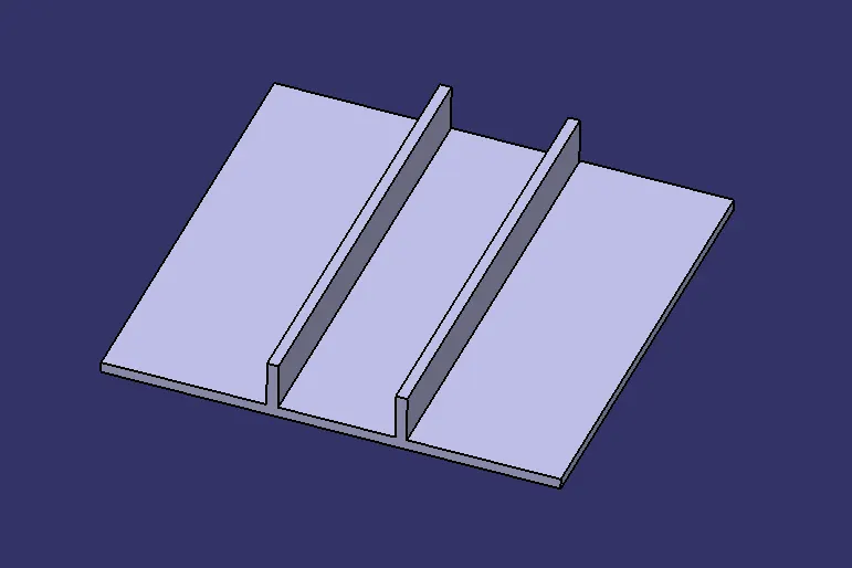
- Now perform union trim on the to form a doghouse with ribs.
Draft Analysis:
Map Pocket:
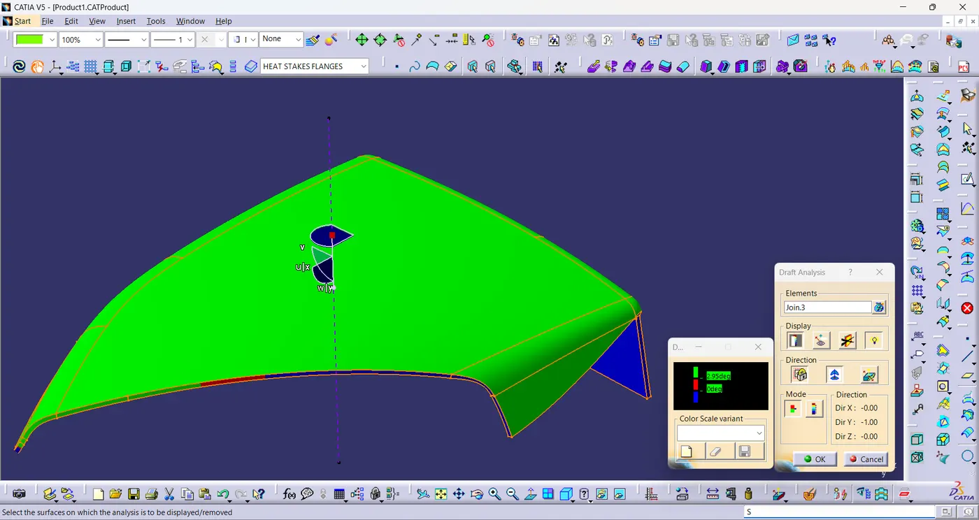
- Draft Analysis is performed on plastic component with main tooling Axis.
- Draft is angle is 3°.
- The draft is positive for class-A surface because the minimum draft angle is 3°.
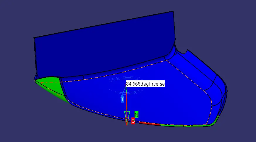
- The minimum draft angle is at this surface is 84.668°.
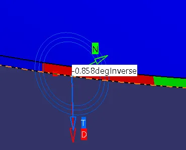
- The minimum draft angle is at this surface is -0.858°.
- Draft Analysis is performed on solid component with main tooling Axis.
- Draft is angle is 3°.
- The draft is positive for class-A surface because the minimum draft angle is 3°.
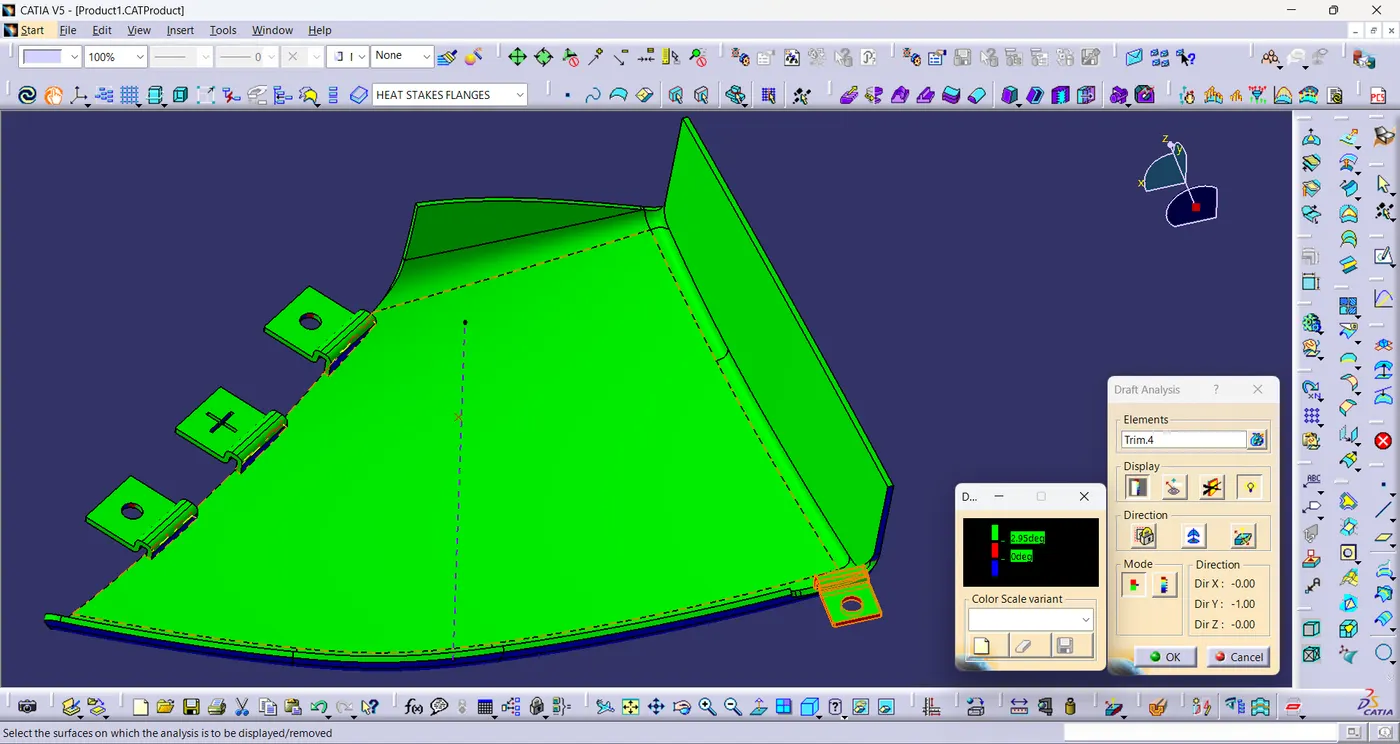
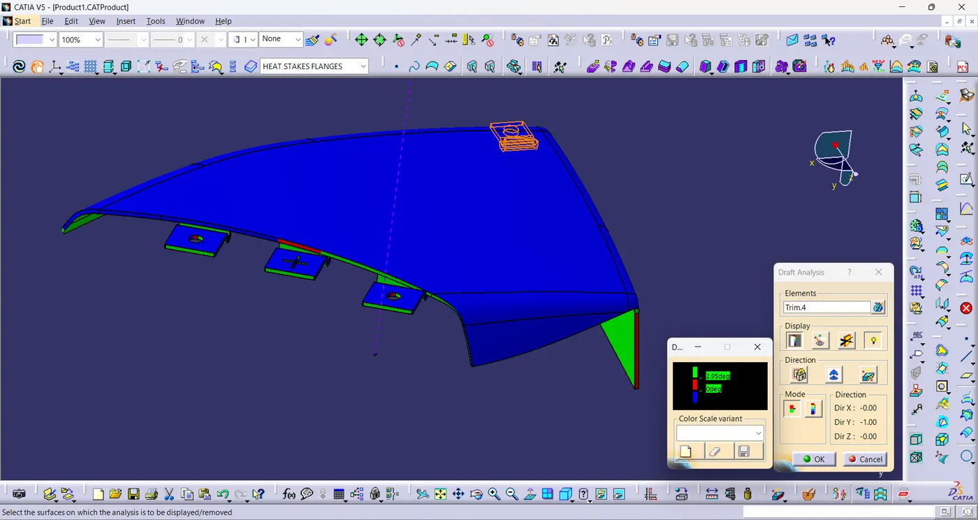
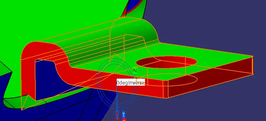
- The minimum draft angle is at this surface is 0°.
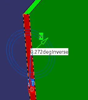
- The minimum draft angle is at this surface is 0.272°.
Bottle Holder:
- Draft Analysis is performed on plastic component with main tooling Axis.
- Draft is angle is 3°.
- The draft is positive for class-A surface because the minimum draft angle is 3°.
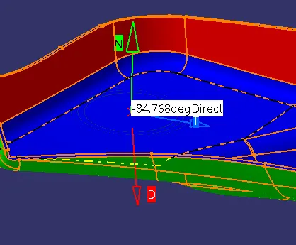
- The minimum draft angle is at this surface is -84.768°.
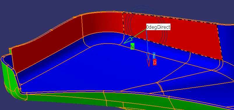
- The minimum draft angle is at this surface is 0°.
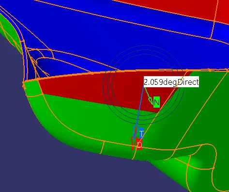
- The minimum draft angle is at this surface is 2.059°.
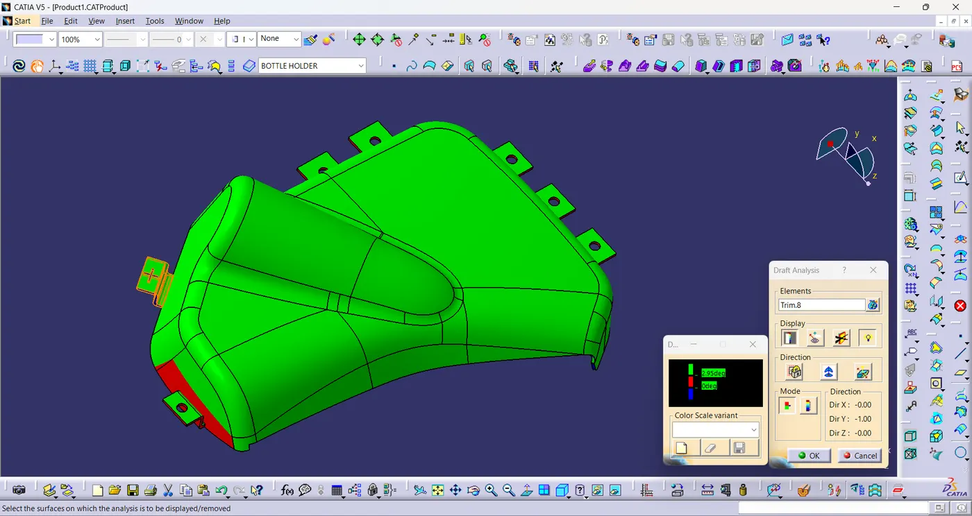
- Draft Analysis is performed on solid component with main tooling Axis.
- Draft is angle is 3°.
- The draft is positive for class-A surface because the minimum draft angle is 3°.
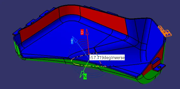
- The minimum draft angle is at this surface is -57.719°.
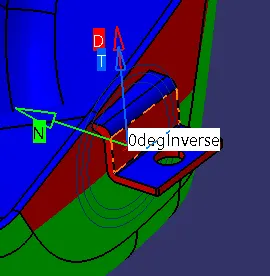
- The minimum draft angle is at this surface is 0°.
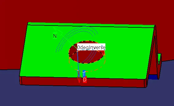
- The minimum draft angle is at this surface is 0°.
Lower Substrate:
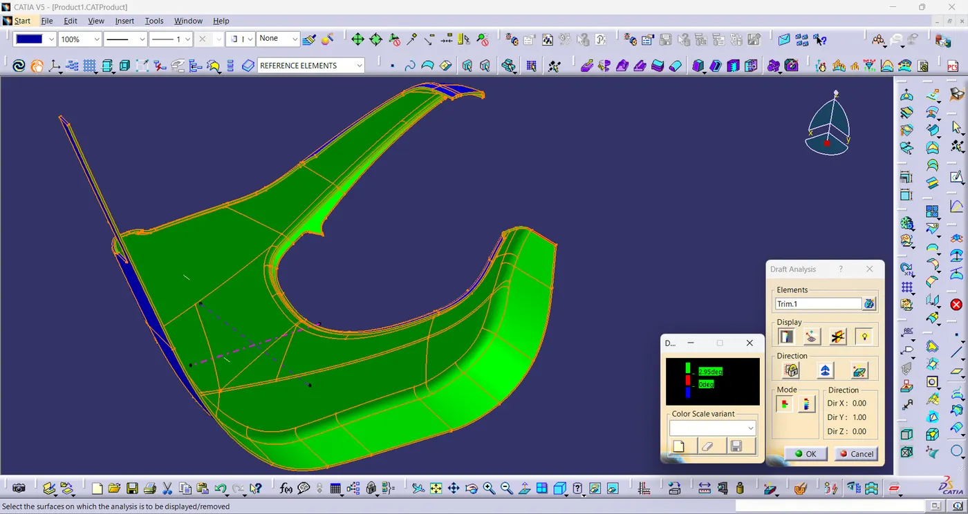
- Draft Analysis is performed on plastic component with main tooling Axis.
- Draft is angle is 3°.
- The draft is positive for class-A surface because the minimum draft angle is 3°.
- Draft Analysis is performed on solid component with main tooling Axis.
- Draft is angle is 3°.
- The draft is positive for class-A surface because the minimum draft angle is 3°.
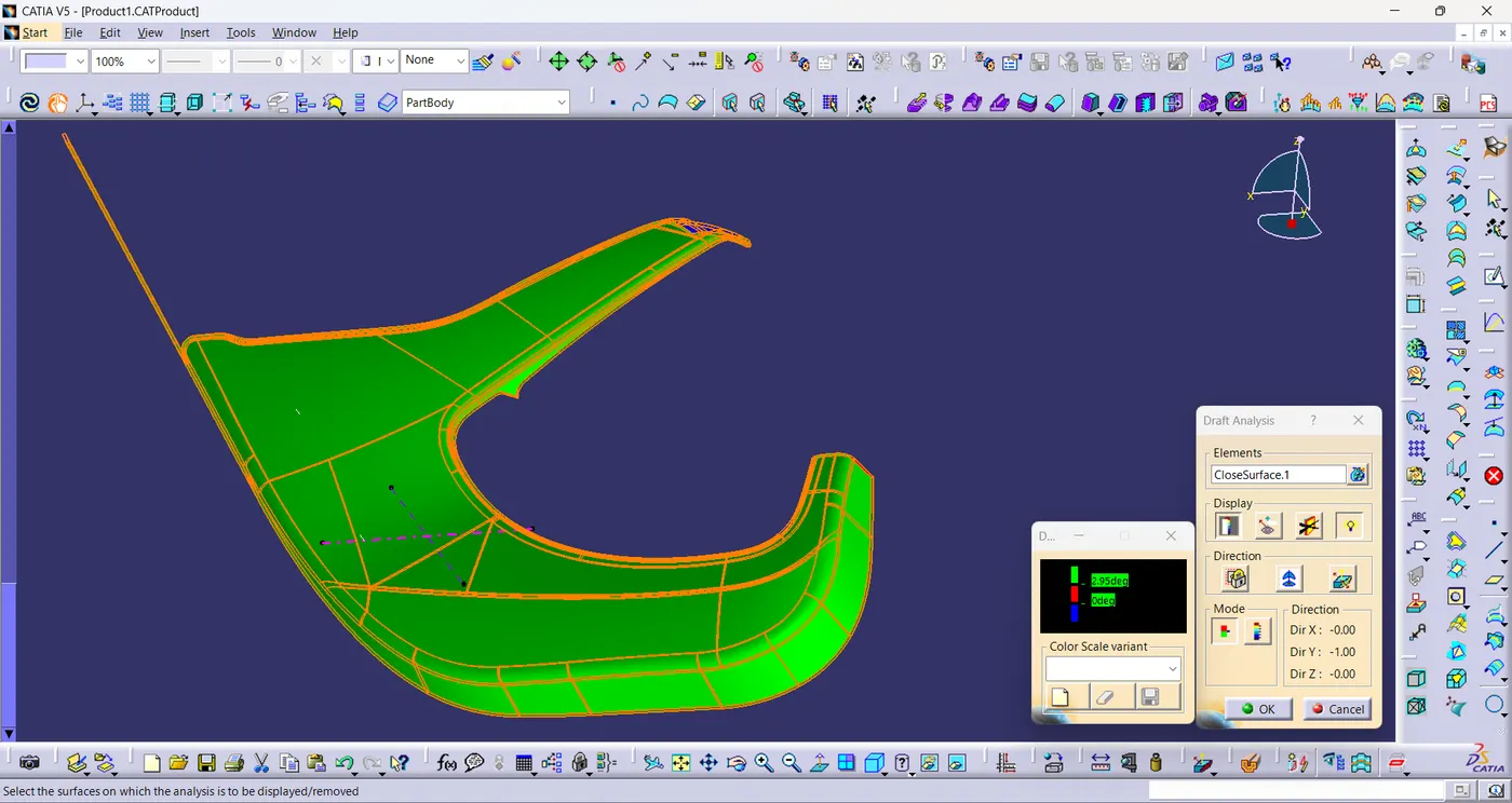
- The minimum draft angle is at this surface is -82.06°.
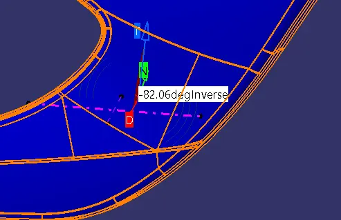
- The minimum draft angle is at this surface is 0.22°.
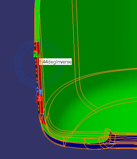
- Draft Analysis is performed on solid component with main tooling Axis.
- Draft is angle is 3°.
- The draft is positive for class-A surface because the minimum draft angle is 3°.
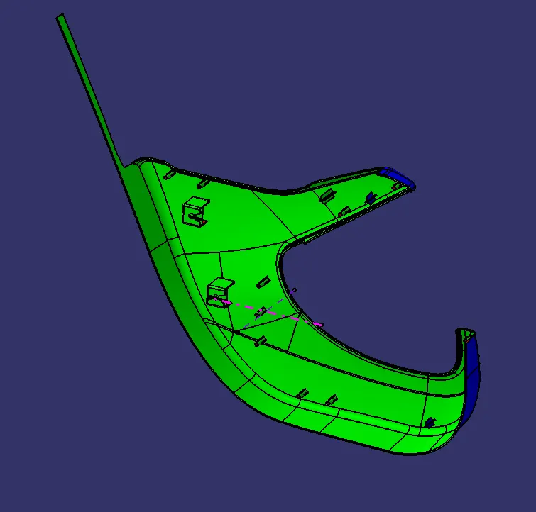
- Draft Analysis is performed on solid component with side core tooling Axis.
- Draft is angle is 3°.
- The draft is positive for class-A surface because the minimum draft angle is 3°.
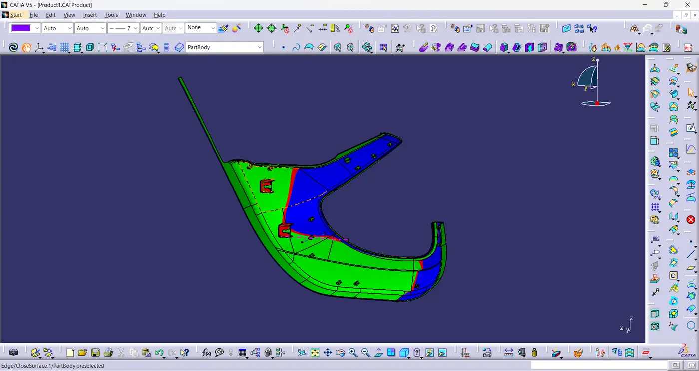
Arm Rest:
- Draft Analysis is performed on plastic component with side core tooling Axis.
- Draft is angle is 3°.
- The draft is positive for class-A surface because the minimum draft angle is 3°.
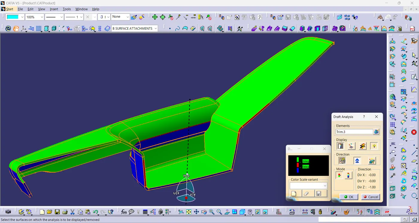
- The minimum draft angle is at this surface is -22.717°.
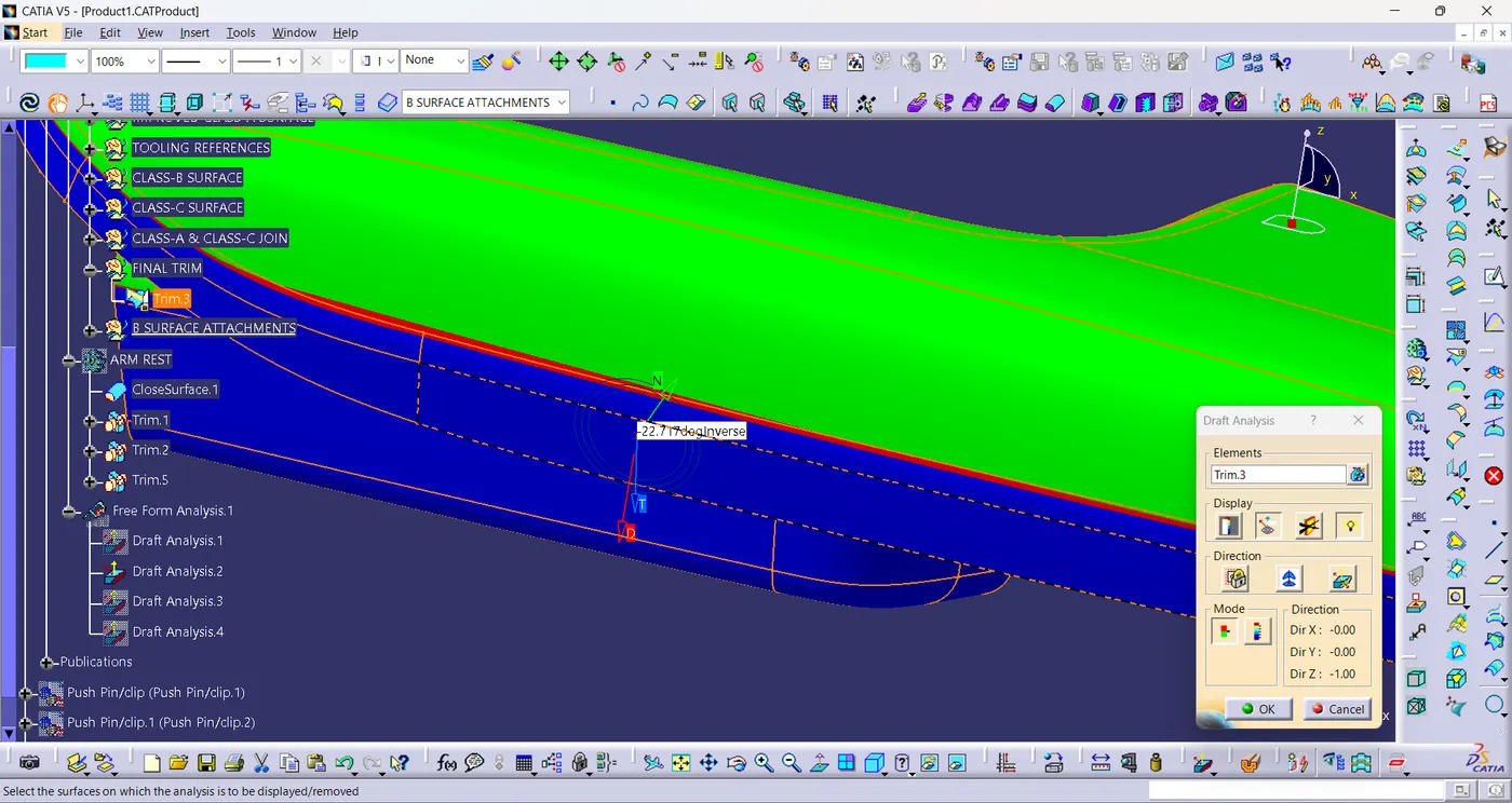
- The minimum draft angle is at this surface is -23.823°.
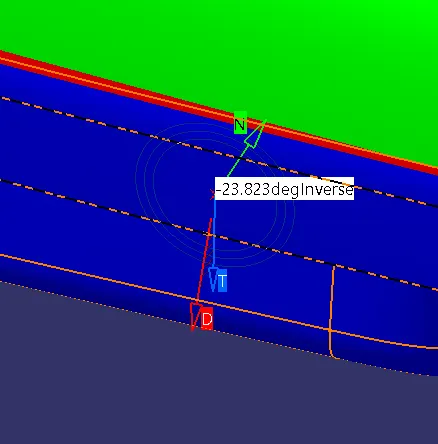
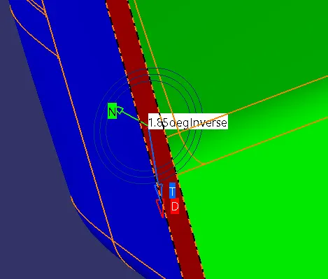
- The minimum draft angle is at this surface is 1.85°.
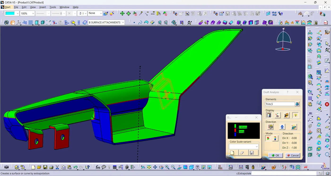
- Draft Analysis is performed on solid component with side core tooling Axis.
- Draft is angle is 3°.
- The draft is positive for class-A surface because the minimum draft angle is 3°.
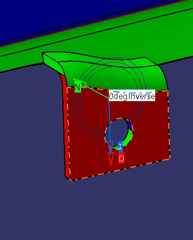
- The minimum draft angle is at this surface is 0°.
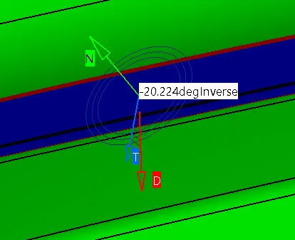
- The minimum draft angle is at this surface is -20.224°.
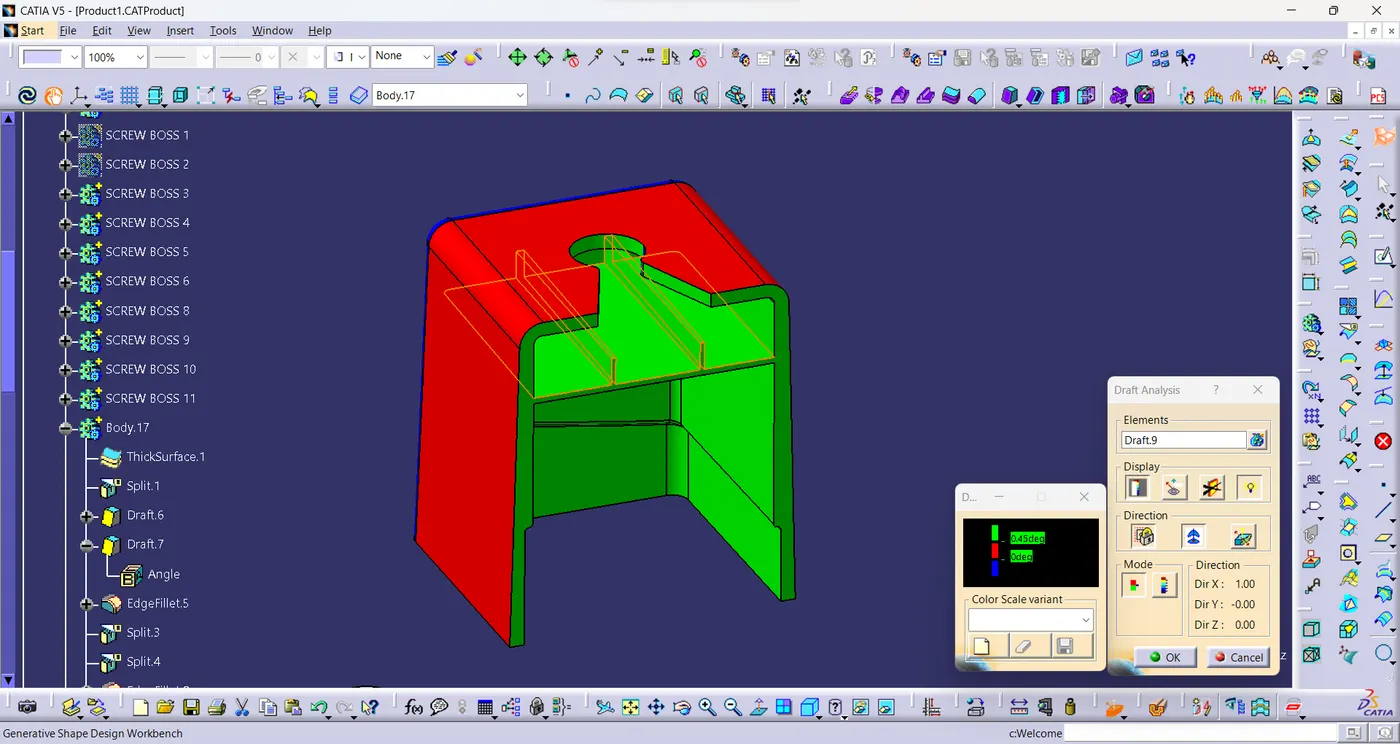
- Draft Analysis is performed on doghouse with side core tooling Axis.
- Draft is angle is 0.5°.
- The draft is positive for class-A surface because the minimum draft angle is 0.5°.
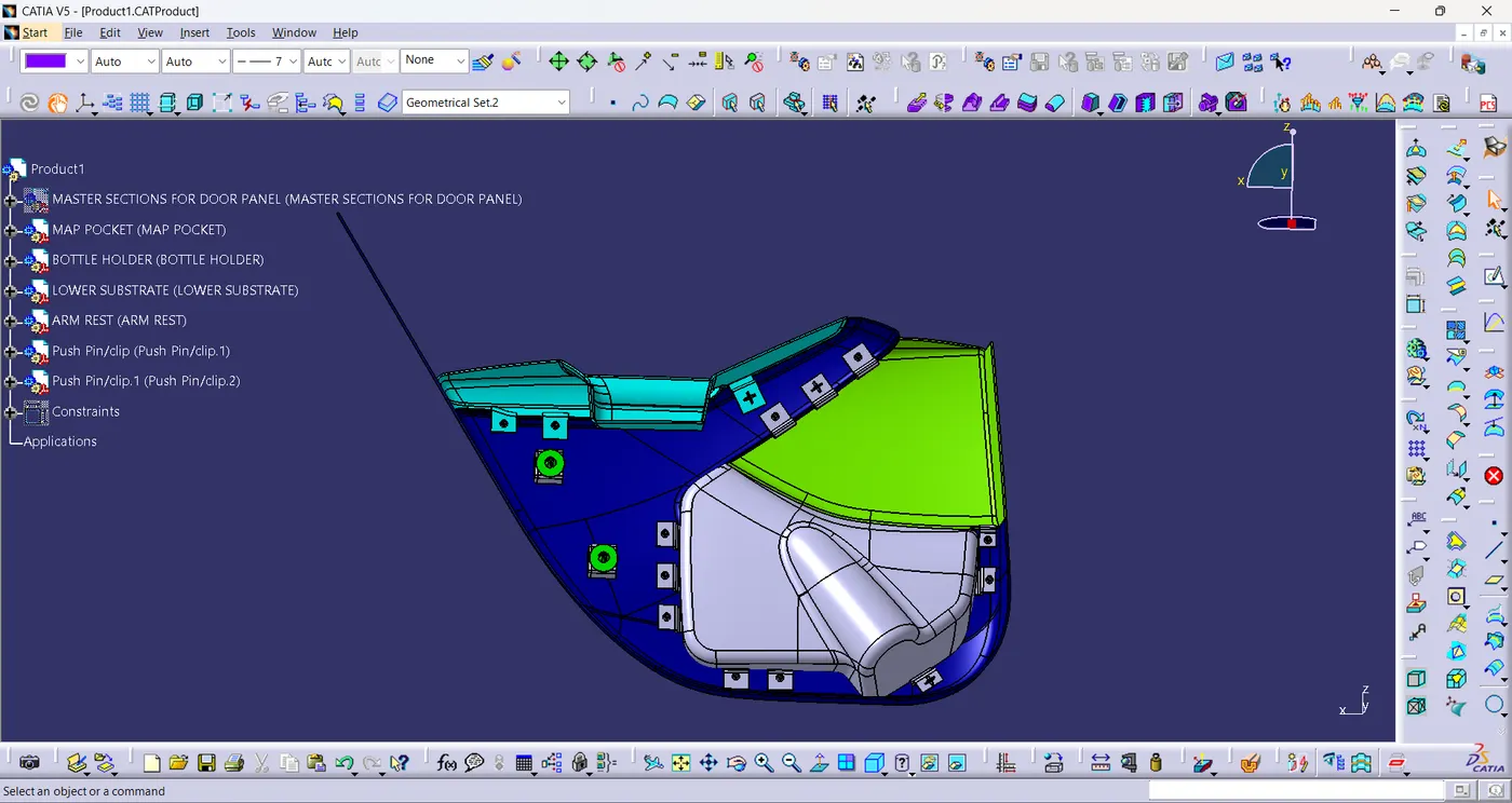
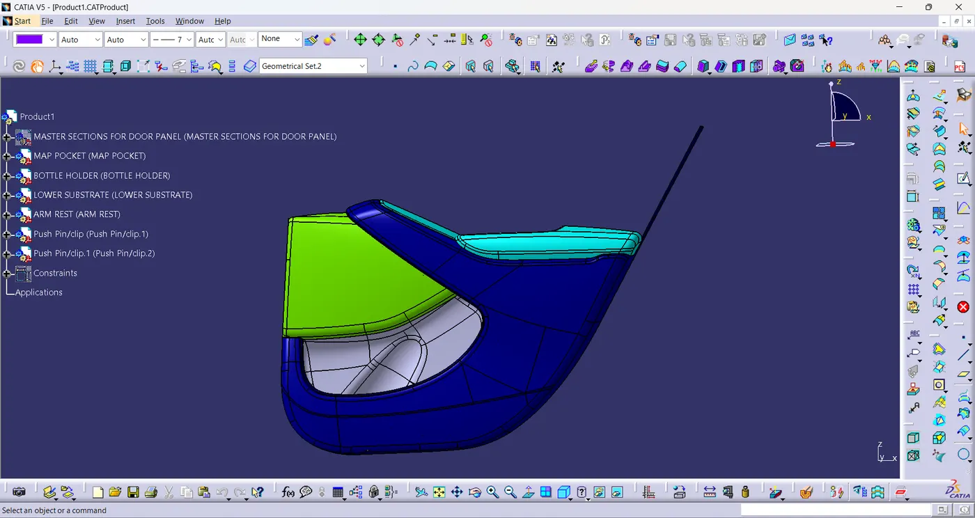
Final Assembly:
Graph Tree:
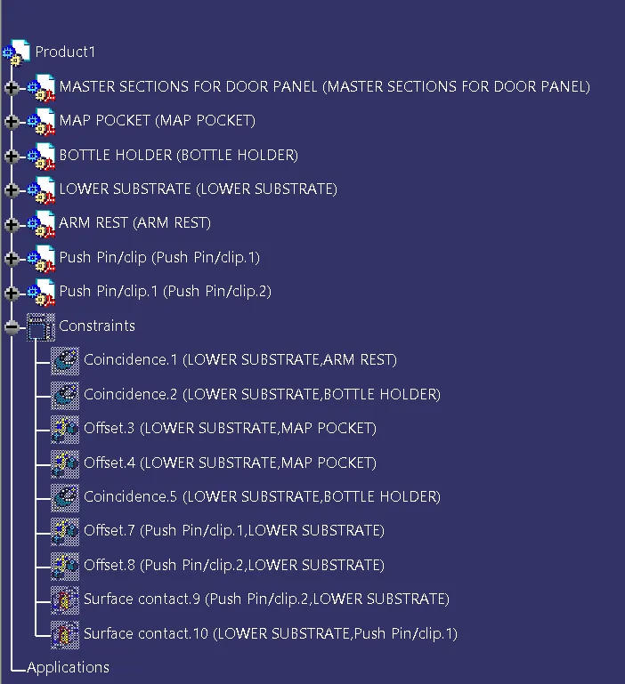
Conclusion:
- Tooling Axis are created individually.
- Plastic component is created with mastersection.
- Door Panel thickened part is created with mastersection.
- Solid model of Door Panel is created and Draft Analysis is performed on the Class-A surface,Plastic component,solid component,Doghouse.
- Mounting features are created as per design guide lines.
- Push pin is attached with dog house.