Week 9 - Challenge 2 - Switch Bezel Design
AIM/OBJECTIVE:
- Create the Switch Bezel Plastic component through the given Class-A surface. To begin with, the tooling axis for the given Class-A Surface should be created meeting the requirements of the draft angle and at the end perform the Draft analysis on the model.
- Take the Thickness of the component to be 2.5 mm
Report:
- This is a Class A Surface in which there are there are two holes,two ribs,a flat surface connecting two ribs and the base surface.
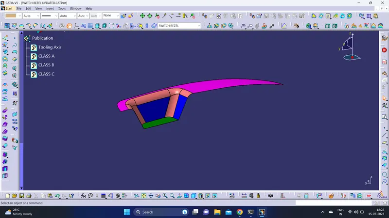
- Extract the base surface .
- Create a point in the centre of the base.
- Using Intersection command an intersection is created for the given class A surface.
- Two inclined lines are drawn on intersection.
- using bisecting line, created a bisecting line of two inclined line in the sketch 1.
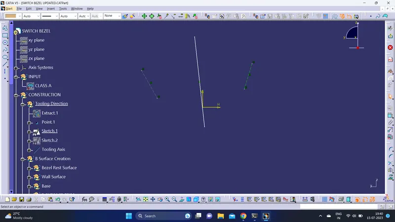
- Using Intersection command an intersection is created for the given class A surface.
- An inclined line is drawn on intersection.
- A line is created in the Z-direction.
- Gave an angle of 6 degree between the inclined line and the line drawn in sketch 2.
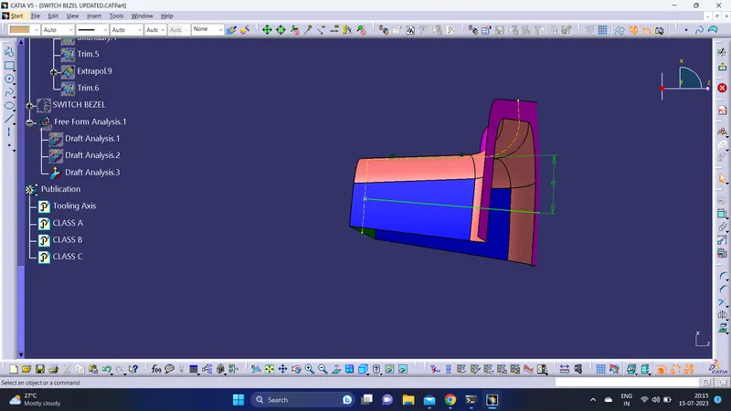
- Using bisecting line method, a tooling axis is created in the direction of z - direction.
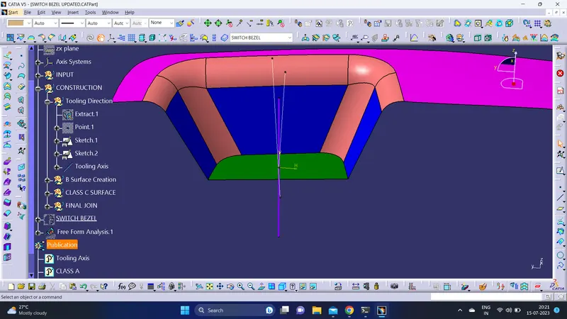
B- SURFACE CREATION:
BEZEL REST SURFACE:
- Extract the surface from the class A surface.
- Untrim the extracted surface.
- Offset the created surface to distance of 2.5mm.
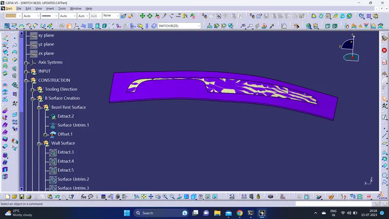
WALL SURFACE:
- Extract the wall surface from the class A surface.
- Untrim the extracted surface.
- Extrapolate the untrimmed surface.
- Offset the created wall surface to distance of 2.5mm.
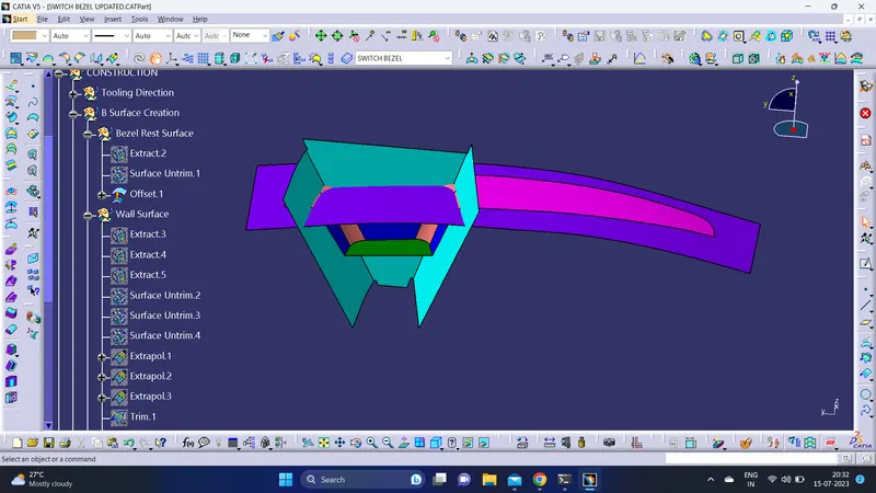
WALL:
- Extract the Base surface from the class A surface.
- Untrim the extracted surface.
- Extrapolate the untrimmed surface.
- Offset the created Base surface to distance of 2.5mm.

FINAL TRIM:
- Now trim the unwanted surface.
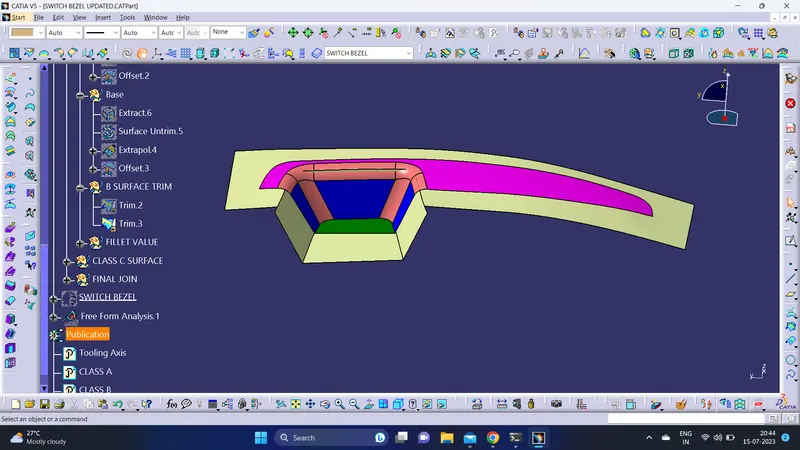
- Fillet the edges by 15-2.5=12.5mm(fillet radius of classA surface-thickness of surface.)
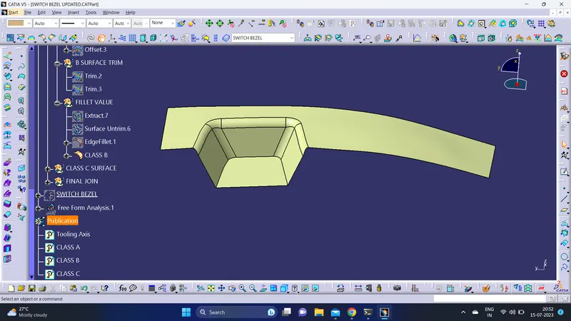
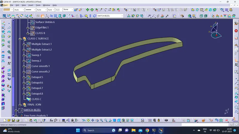
CLASS - C SURFACE CREATION:
- Create the multiple extract of class A surface.
- Sweep the multiple extract to form class c surface.
- Using the curve smooth command, the patches formed on the surface are removed.
- Extrapolate the edge and then trim the unwanted surface.
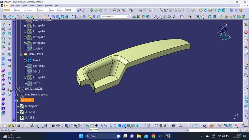
Join:
- Join the class A and class C surface together.
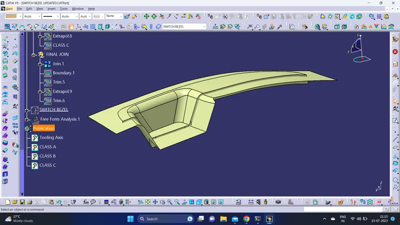
Trim:
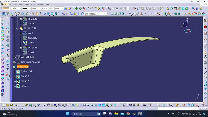
- Trim the unwanted surfaces to form the plastic component of switch bezel of thickness 2.5mm through class A surface.
Platic Component:
CLOSE SURFACE:
- Use the Close Surface feature to make a solid body from the plastic component.
Isometric View:
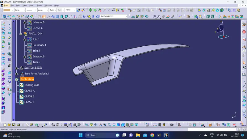
Front View:
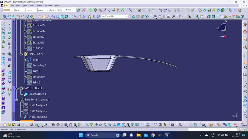
Top View:
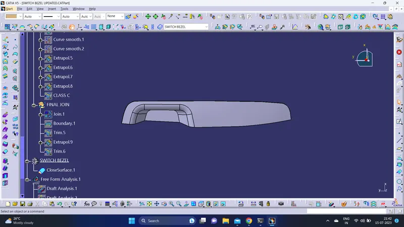
Side View:
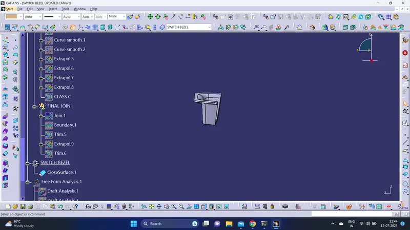
DRAFT ANALYSIS:
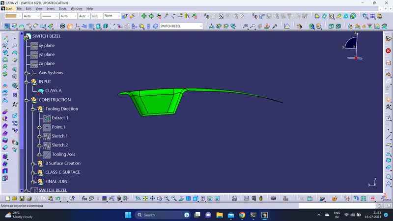
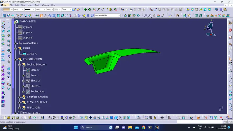
On Class-A surface:
- Use the Draft analysis command to perform analysis on the Class-A surface.
- Adjust the compass onto the tooling axis to run the draft analysis.(Draft Angle=3 deg).
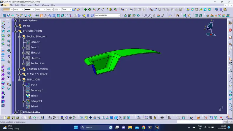
On final plastic component:
- Use the Draft analysis command to perform analysis on the plastic component.
- Adjust the compass onto the tooling axis to run the draft analysis.(Draft Angle=2.9 deg).
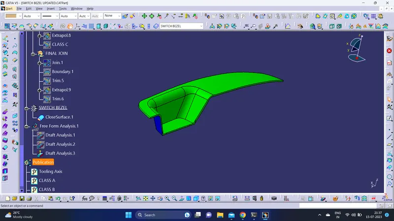
On solid model:
- Use the Draft analysis command to perform analysis on the solid model.
- Adjust the compass onto the tooling axis to run the draft analysis.(Draft Angle=2.9 deg).
Publications:
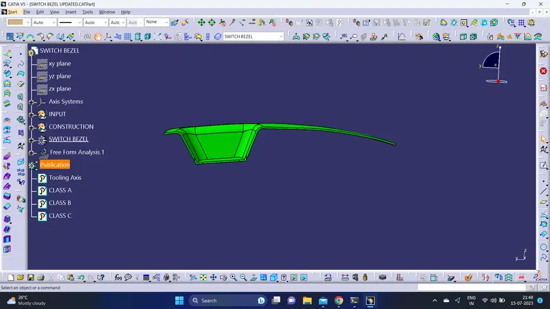
- Using Publications command published Class - A,B,C surfaces,Tooling Axis and part boy for easy acess.
CONCLUSION:
- Tooling axis and plastic component is created.
- Draft analysis is performed over the class - A surface and the solid model.