Week 9 - Challenge 1 - Base Bracket Design
REPORT:
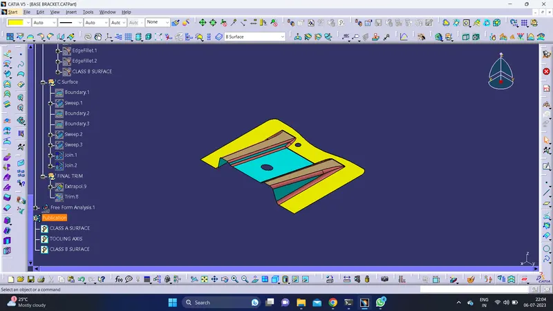
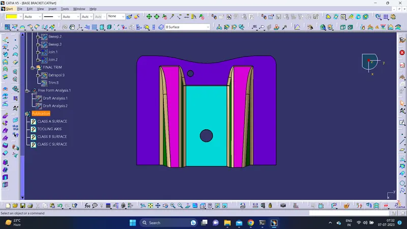
- This is a Class A Surface in which there are there are two holes,two ribs,a flat surface connecting two ribs and the base surface.
Objective:
- To create the Base Bracket Plastic component through the given Class-A surface.
- To create the tooling axis for the plastic component.
- To perform draft analysis over the class A surface and the model.
CLASS-B SURFACE:
Tooling Axis:
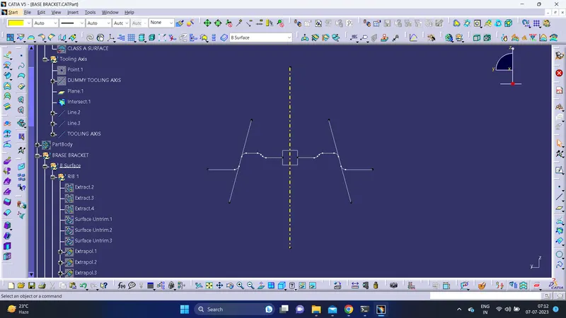
- Using Intersection command an intersection is created for the given class A surface.
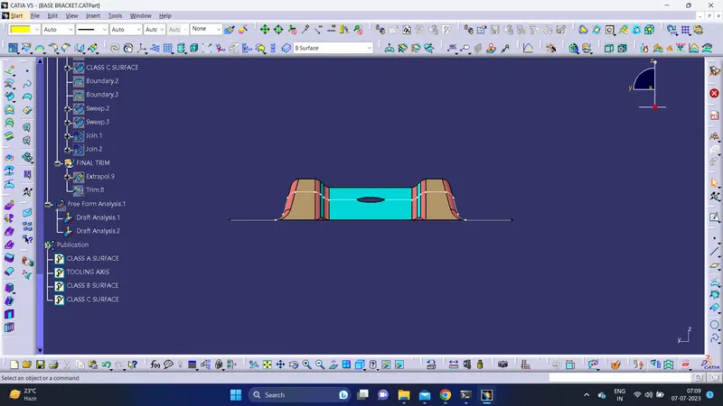
- Surface lines are created with point to point line type.
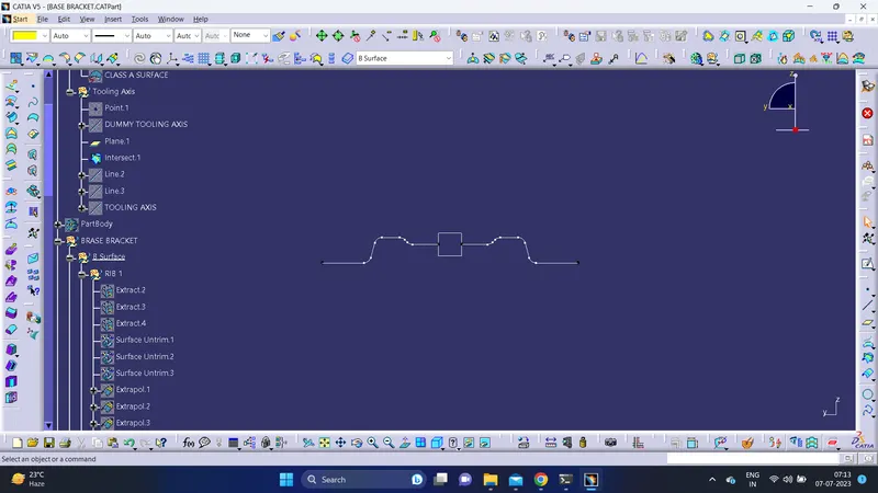
- Dummy tooling axis is created with point and direction line type.
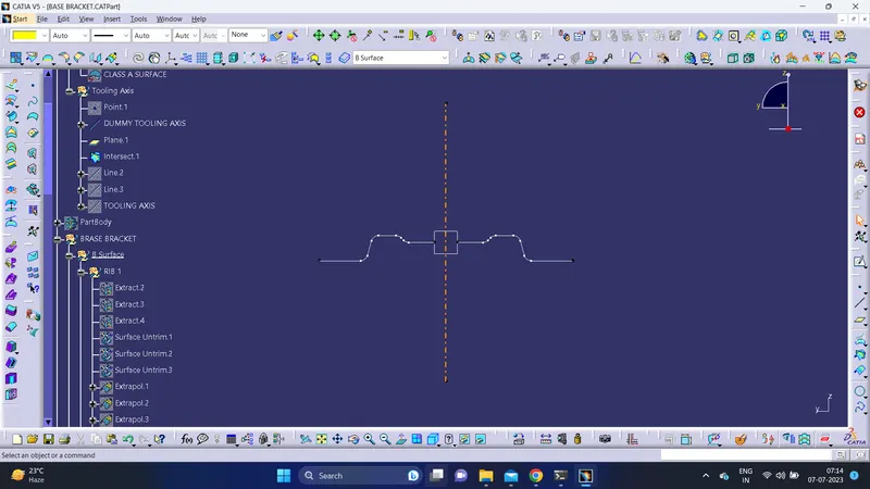
- By using Bisecting method,the suitable tooling axis is created in z-direction.
DRAFT ANALYSIS:
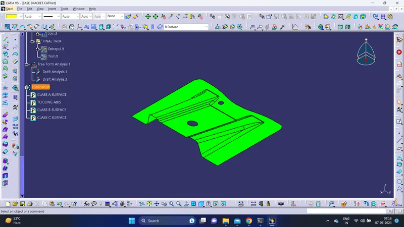
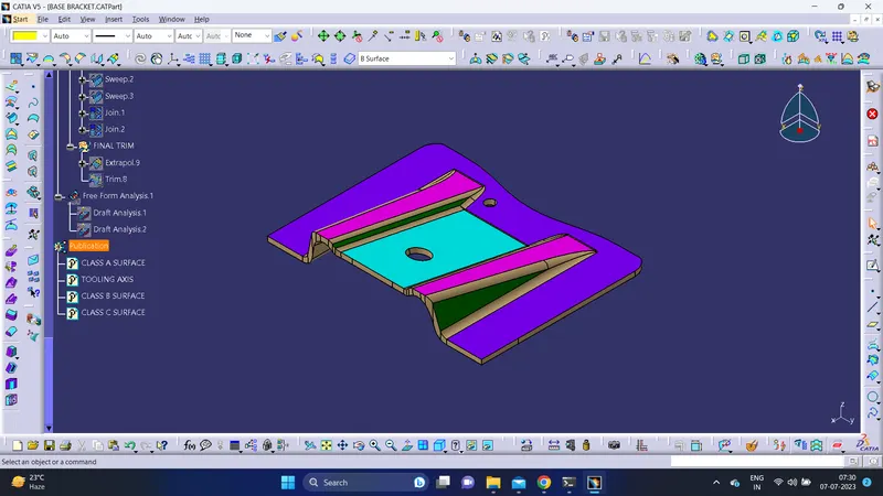
- Use the Draft analysis command to perform analysis on the Class-A surface.
- Adjust the compass onto the tooling axis to run the draft analysis.(Draft Angle=3 deg).
Rib Creation:
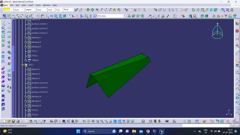
- Extract the rib surface from the class A surface.
- Untrim the extracted surface.
- Extrapolate the untrimmed surface.
- Trim the unwanted surface.
- Offset the created rib surface to distance of 2.5mm.
- Repeat the above steps for the next rib.
Connecting Surface:
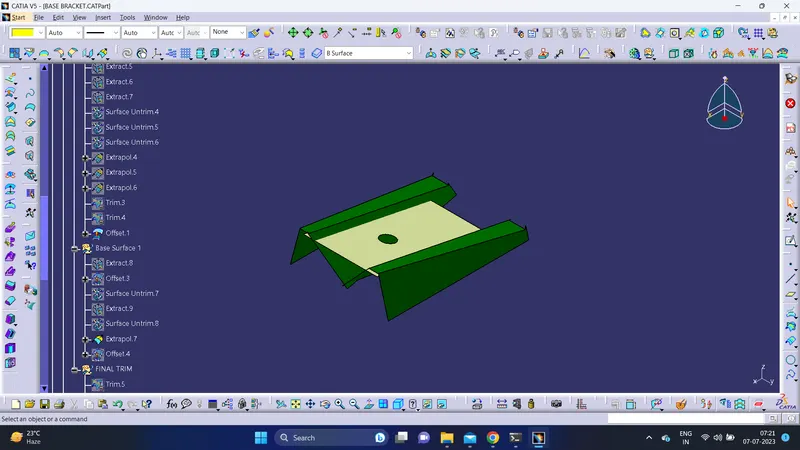
- Extract the Flat connecting surface from the class A surface.
- Untrim the extracted surface.
- Extrapolate the untrimmed surface.
- Offset the created flat connecting surface to distance of 2.5mm.
- Trim the unwanted surface.
Base Surface:
- Extract the base from the class A surface.
- Untrim the extracted surface.
- Extrapolate the untrimmed surface.
- Offset the created base to distance of 2.5mm.
- Trim the unwanted surface.
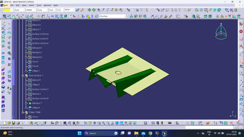
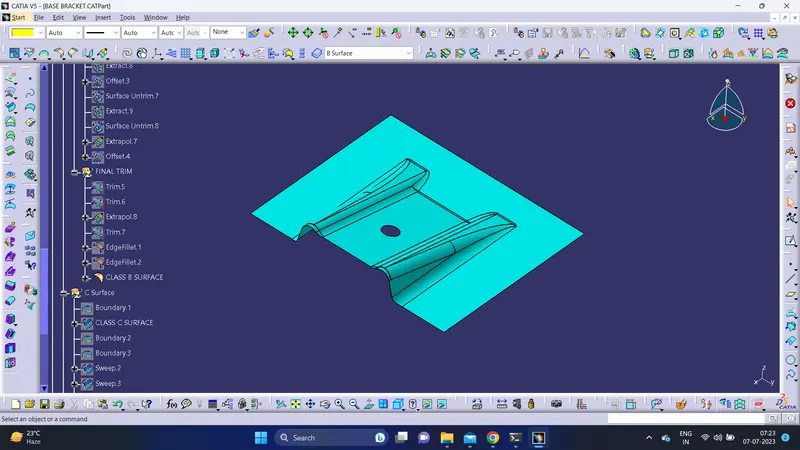
Fillet:
- Fillet the edges of class B surface of radius 3mm and add the offset distance 2.5mmto it,for the component to form equal wall thickness.(Fillet value = radius of fillet + thickness of the component/offset distance.).
CLASS-C SURFACE:
- Create the boundary of class A surface.
- Sweep the created boundary to form class c surface.
- Create the boundary of two circles.
- Sweep the boundary of two circles.
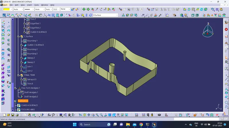
Join:
- using Join command join the class A,class C surface and sweeped circles to together.
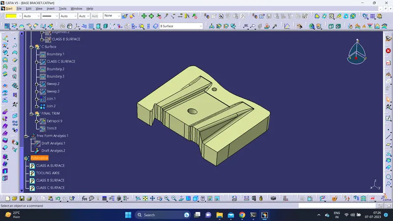
Trim:
- Trim the unwanted surfaces to form the plastic component of base bracket of thickness 2.5mm through class A surface.
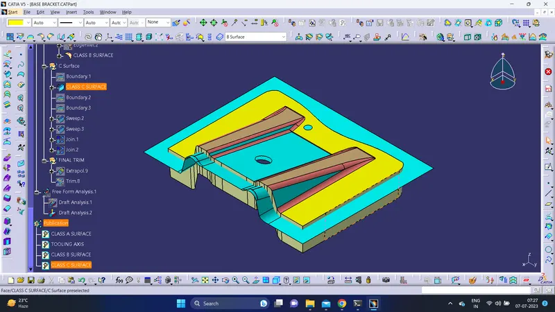
Platic Component:
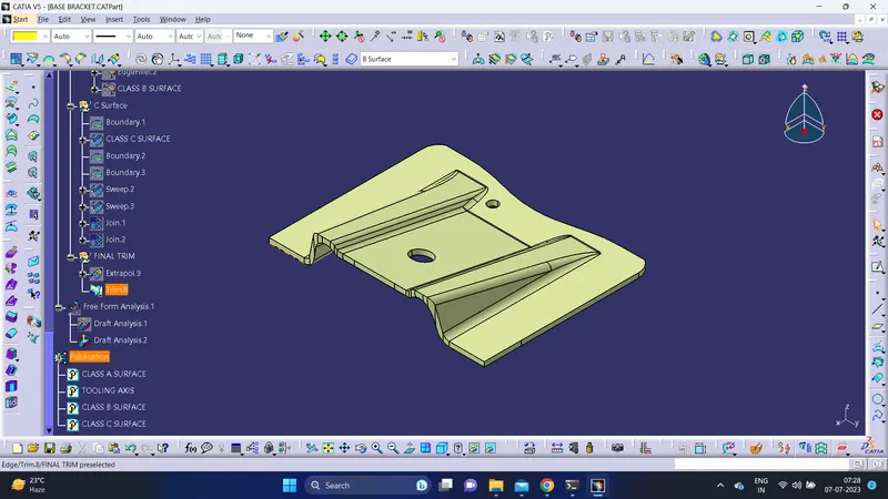
CLOSE SURFACE:
- Use the Close Surface feature to make a solid body from the plastic component.
Isometric View:
Front View:
Top View:
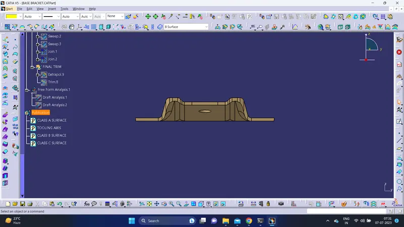
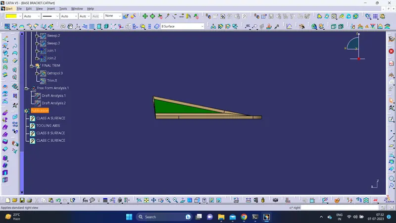
Side View:
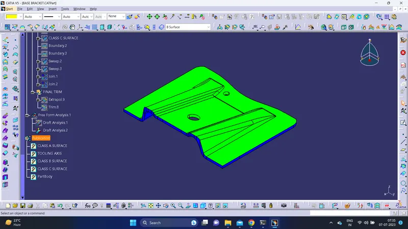
DRAFT ANALYSIS:
- Use the Draft analysis command to perform analysis on the solid model.
- Adjust the compass onto the tooling axis to run the draft analysis.(Draft Angle=3 deg).
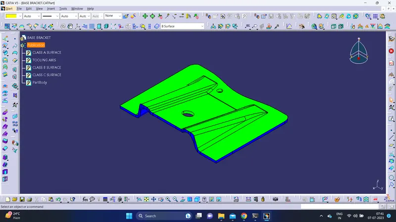
Publications:
- Using Publications command published Class - A,B,C surfaces,Tooling Axis and part boy for easy acess.
CONCLUSION:
- Tooling axis and plastic component is created.
- Draft analysis is performed over the class A surface and the solid model.